
en
de
el
pl
hu
cs
tr
ro
sl
ru
Handling instructions
Bedienungsanleitung
Οδηγίες χειρισμού
Instrukcja obsługi
Kezelési utasítás
en
de
el
pl
hu
Návod k obsluze
Kullanım talimatları
Instrucţiuni de utilizare
Navodila za rokovanje
Инструкция по эксплуатации
cs
tr
ro
sl
ru
CG 40EAS (P) / CG 40EAS (LP)
CG40EAS (P)

2
1
R
T
O
A
C
L
J
P
K
CG40EAS (LP)
M
D
E
N
F
G
I
B
H
G
E
N
F
H
I
M
B
CG40EAS (P)
K
D
Q
S
23
1
2
3
4
5
6
7
1/3
2/3

3
4
8
5
9
6
10
7
11
12
13
8 9
14
10 12
14
15
16
17
18
19
20
11 1313
20

4
14 15 16
23
22
21
17 18
25
A
B
19
24
20 21 22
26
11
12
29
11
27
28
26
ab
23 24 25
21

5
26 27 28
T
30
31
32
29 30 31
33
32 33 34
34
10 cm
10 cm
10 cm
35
35
36
36 37

English
6
(Original instructions)
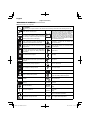
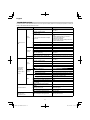
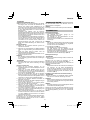
MEANINGS OF SYMBOLS
NOTE: Some units do not carry them.
Symbols
WARNING
The following show symbols used for the machine. Be sure that you understand their meaning before use.
Grass Trimmer / Brush Cutter
Blade thrust may occur when the spinning
blade contacts a solid object in the critical area.
A dangerous reaction may occur causing the
entire unit and operator to be thrust violently.
This reaction is called blade thrust. As a result,
the operator may lose control of the unit which
may cause serious or fatal injury. Blade thrust is
more likely to occur in areas where it is diffi cult
to see the material to be cut.
It is important that you read, fully understand
and observe the following safety precautions
and warnings. Careless or improper use of the
unit may cause serious or fatal injury.
Read, understand and follow all warnings and
instructions in this manual and on the unit.
Hot Surface – Contact with hot surface can
cause serious burns.
Always wear eye, head and ear protectors when
using this unit.
Indicate handle location. Do not attach handle
above this point.
Keep all children, bystandards and helpers
15 m away from the unit. If anyone approaches
you, stop the engine and cutting attachment
immediately.
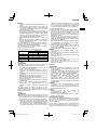
Displacement
Be careful of thrown objects. Spark plug
min
-1
Shows maximum shaft speed. Do not use the
cutting attachment whose max rpm is below the
shaft rpm.
Idle
Idling speed
Gloves should be worn when necessary, e.g.,
when assembling cutting equipment.
Speed of output shaft
Use anti-slip and sturdy footwear.
P
Max. engine output
Choke – Run position (Open) Fuel tank capacity
Choke – Start position (Closed)
Dry weight (without fuel, cutting attachment,
harness and cutting attachment guard)
START
On/Start Cutting attachment
STOP
Off /Stop
L
pA, eq
ISO22868
Sound pressure level LpA by ISO 22868
Equivalent*
Fuel and oil mixture
L
WA, Ra(M)
2000/14/EC
Measured sound power level LwA by 2000/14/
EC
Racing
Idle speed adjustment
L
WA, Ra(G)
2000/14/EC
Guaranteed sound power level LwA by
2000/14/EC
Racing
Priming pump
a
hv, eq(F)
Vibration level by ISO 22867
Front or Left handle / Equivalent*
Guaranteed sound power level
a
hv, eq(R)
Vibration level by ISO 22867
Rear or Right handle / Equivalent*

English
7
K
Uncertainty
Before using your machine
• Read the manual carefully.
• Check that the cutting equipment is correctly assembled and adjusted.
• Start the unit and check the carburetor adjustment. See “MAINTENANCE”.
NOTE: Equivalent noise level / vibration level are calculated as the time-weighted energy total for noise / vibration levels
under various working conditions with the following time distribution:
* 1/2 Idle, 1/2 racing.
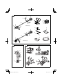
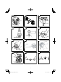
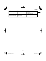
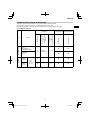
WHAT IS WHAT? (Fig. 1)
Since this manual covers several models, there may be
some diff erence between pictures and your unit. Use the
instructions that apply to your unit.
A: Fuel cap
B: Throttle trigger
C: Starter handle
D: Cutting attachment guard
E: Cutting attachment
F: Drive shaft tube
G: Handle
H: Hanger
I: Ignition switch
J: Harness
K: Throttle trigger lockout
L: Choke lever
M: Engine
N: Gear case
O: Combi box spanner
P: Handling instructions
Q: Goggles
R: Hex bar wrench
S: Blade cover (if so equipped)
T: Spanner
WARNINGS AND SAFETY
INSTRUCTIONS
Pay special attention to statements preceded by the
following words:
WARNING
Indicates a strong possibility of severe personal injury or
loss of life, if instructions are not followed.
CAUTION
Indicates a possibility of personal injury or equipment
damage, if instructions are not followed.
NOTE
Helpful information for correct function and use.
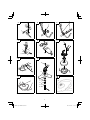
Operator safety
○ Wear head protection (1). (Fig. 2)
○ Always wear a safety face shield or goggles (2). (Fig. 2)
○ Wear approved hearing protection (3). (Fig. 2)
Long-term exposure to noise can result in permanent
hearing impairment.
Pay attention to your surroundings. Be aware of any
bystanders who may be signaling a problem.
Remove safety equipment immediately upon shutting off
engine.
○ Always wear heavy, long-sleeved shirts (4) and long
pants (5) and non-slip boots (6) and gloves (7). (Fig. 2)
Do not wear loose clothing, jewelry, short pants, sandals
or go barefoot.
Secure hair so it is above shoulder length.
○ Do not operate this tool when you are tired, ill or under
the infl uence of alcohol, drugs or medication.
○ Do not operate the tool at night or under bad weather
conditions when visibility is poor. And do not operate the
tool when it is raining or right after it has been raining.
Working on slippery ground could lead to an accident if
you lose your balance.
○ Never let a child or inexperienced person operate the
machine.
○ Do not start the engine if there are any fl ammables such
as dry leaves, waste paper or fuel in the vicinity.
○ Never start or run the engine inside a closed room or
building. Breathing exhaust fumes can kill.
○ Keep handles free of oil and fuel.
○ Keep hands away from cutting equipment.
○ Do not grab or hold the unit by the cutting equipment.
○ Gloves should be worn when installing or removing the
cutting attachment. Failure to do so may result in injury.
○ When the unit is shut off , make sure the cutting
attachment has stopped before the unit is set down.
○ When operation is prolonged, take a break periodically
so that you may avoid possible Hand-Arm Vibration
Syndrome (HAVS) which is caused by vibration.
WARNING
○ Always operate the tool with proper protective equipment
and clothing. Failure to do so may result in accidents
such as burns or injuries. (Fig. 2)
○ Do not touch the spark plug area or high voltage during
operation. Doing so may result in electric shock.
○ Do not allow children near the tool during operation.
○ Do not touch the engine, muffl er cover or exhaust vent
during or shortly after operation. Doing so may result in
burn or injury.
○ Antivibration systems do not guarantee that you will
not sustain Hand-Arm Vibration Syndrome or carpal
tunnel syndrome. Therefore, continual and regular users
should monitor closely the condition of their hands and
fi ngers. If any of the above symptoms appear, seek
medical advice immediately.
○ If you are using any medical electric/electronic devices
such as a pacemaker, consult your physician as well as
the device manufacturer prior to operating any power
equipment.
Unit/machine safety
○ Inspect the entire unit/machine before each use.
Replace damaged parts. Check for fuel leaks and make
sure all fasteners are in place and securely tightened.
○ Replace parts that are cracked, chipped or damaged in
any way before using the unit/machine. Faulty parts may
increase the risk of accidents and may lead to an injury.
○ Make sure the cutting attachment guard and harness are
properly attached. Do not operate if cutting attachment
guard and harness is not properly attached.
○ Keep others away when making carburetor adjustments.
○ Use only accessories as recommended for this unit/
machine by the manufacturer.
○ Before operation, make sure that there are no tools such
as the adjustment key or spanner still attached to the
unit.

English
8
WARNING
○ Never modify the unit/machine in any way. Do not use
your unit/machine for any job except that for which it is
intended.
○ Non-authorized modifi cations and/or accessories may
result in serious personal injury or the death of the
operator or others.
Fuel safety
○ Mix and pour fuel outdoors and where there are no
sparks or fl ames.
○ Use a container approved for fuel.
○ Move at least 3 m away from fueling site before starting
engine.
○ Stop engine before removing fuel cap. Do not remove
the fuel cap during operation.
○ Empty the fuel tank before storing the unit/machine. It is
recommended that the fuel be emptied after each use. If
fuel is left in the tank, store so fuel will not leak.
WARNING
○ Fuel is easy to ignite or get explosion or inhale fumes, so
that pay special attention when handling or fi lling fuel.
○ Do not smoke or allow smoking near fuel or the unit/
machine or while using the unit/machine.
○ Wipe up all fuel spills before starting engine.
○ Store unit/machine and fuel in area where fuel vapors
cannot reach sparks or open fl ames from water heaters,
electric motors or switches, furnaces. etc.
○ When using the unit in dry areas, make sure that fi re
extinguishing equipment is readily available.
○ If you shut off the engine for refueling, make sure the unit
has cooled down before adding fuel.
Cutting safety
○ Do not cut any material other than grass and brush.
○ Inspect the area to be cut before each use.
Remove objects which can be thrown or become
entangled.
Do not operate in areas where there are tree roots or
rocks.
○ For respiratory protection, wear an aerosol protection
mask when cutting the grass after insecticide is
scattered.
○ Keep others including children, animals, bystanders and
helpers outside the 15 m hazard zone. Stop the engine
immediately if you are approached.
○ Please exercise caution as engine startup may be
delayed after pulling the starter handle.
○ Always keep the engine on the right side of your body.
○ Hold the unit/machine fi rmly with both hands.
○ Keep fi rm footing and balance. Do not over-reach.
Losing your balance during work may lead to an injury.
○ Keep all parts of your body away from the muffl er and
cutting attachment when the engine is running.
○ Keep cutting attachment below knee level.
○ Please exercise caution when operating in areas where
electrical cables or gas pipes are present.
○ Do not operate the cutting attachment for anything but
clearing grass or bushes. Avoid operations where the
cutting attachment may touch water such as puddles
or dig into dirt. Failure to do so may result in injury or
damage to the unit.
○ Avoid prolonged use at low speed range in which
vibration is high. Doing so may result in engine damage.
○ When relocating to a new work area, or inspecting,
adjusting or exchanging the unit’s cutting attachments,
accessories, etc., be sure to shut off the machine and
ensure that all cutting attachments are stopped.
○ Never place the machine on the ground when running.
○ Never touch the cutting attachment when it is rotating.
○ Always ensure that the engine is shut off and any cutting
attachments have completely stopped before clearing
debris or removing grass from the cutting attachment.
○ Always carry a fi rst-aid kit when operating any power
equipment.
○ Turn off the engine and make sure the cutting attachment
has come to a full stop before removing the unit from
your body or before leaving the unit unattended.
○ If you accidentally bump or drop the unit, inspect it
immediately to make sure there are no damage, cracks
or deformations.
○ If the tool is operating poorly and produces strange noise
or vibrations, turn off the engine immediately and ask
your dealer to have it inspected and repaired.
Continued use under these conditions could lead to
injury or tool damage.
○ Use in accordance with local laws and regulations.
WARNING
KICKBACK DANGER (Fig. 3)
When using metal cutting attachments such as blades,
contact with obstacles such as trees or other hard
surfaces with the front or right portion of the spinning
attachment may force the unit to catch on an obstacle,
resulting in a kickback reaction towards the right side of
the operator.
Kickback may occur when the cutting attachment comes
into contact with tree stumps or rocks hidden behind
weeds. Always make sure there are no obstacles hidden
by weeds before starting work.
To minimize the danger of kickbacks when they do occur,
always position the unit to the right side of the body
during operation. With the operator properly positioned
as the cutting attachment rotates, this will reduce the
danger of the unit’s direct contact with the body.
Maintenance safety
○ Maintain the unit/machine according to recommended
procedures.
○ Disconnect the spark plug before performing
maintenance except for carburetor adjustments.
○ Keep others away when making carburetor adjustments.
○ Use only genuine HITACHI replacement parts as
recommended by the manufacturer.
CAUTION
Do not disassemble the recoil starter. There is a
possibility of personal injury with recoil spring.
WARNING
Improper maintenance could result in serious engine
damage or in serious personal injury.
Transport and storage
○ Carry the unit/machine by hand with the engine stopped
and the muffl er away from your body.
○ Allow the engine to cool, empty the fuel tank, and secure
the unit/machine before storing or transporting. Failure to
do so may result in fi re or accidents.
○ Empty the fuel tank before storing the unit/machine. It is
recommended that the fuel be emptied after each use. If
fuel is left in the tank, store so fuel will not leak.
○ Store unit/machine out of the reach of children.
○ Clean and maintain the unit carefully and store it in a dry
place.
○ Make sure engine switch is off when transporting or
storing.
○ When transporting and storing, either remove the cutting
attachment or place the blade cover over the blade.
○ You have to secure the machine during transport to
prevent loss of fuel, damage or injury.
○ If a warning label cannot be read, peels off or becomes
indistinct, replace it with a new one. To purchase new
labels, contact Hitachi Authorized Service Centers.
If situations occur which are not covered in this manual, take
care and use common sense. Contact Hitachi Authorized
Service Centers if you need assistance.

English
9
SPECIFICATIONS
The SPECIFICATIONS of this machine are listed in the table
on page 119.
NOTE
All data subject to change without notice.
ASSEMBLY PROCEDURES
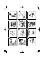
Installation of handle
(1) Loop handle type (Fig. 4)
Attach the handle to the drive shaft tube with the angle
towards the engine.
Adjust the location to the most comfortable position
before operation.
Make sure to securely attach the handle with the 2 bolts.
NOTE
If your unit has handle location label (8) on drive shaft
tube, follow the illustration.
(2) Bike handle type (Fig. 5)
Remove the handle bracket (9) from the assembly.
Place the handle and attach the handle bracket with four
bolts lightly. Adjust to appropriate position. Then attach it
fi rmly with the bolts.
Attach the protection tube to the drive shaft or handle
using cord clamps (10). (Fig. 6)
Installation of harness
WARNING
If the product includes a harness, always make sure to
use it.
Attach the harness hook (11) to the hanger (12) on the drive
shaft tube. (Fig. 7)
Adjust the length of the harness for easy operation of the
tool.
NOTE
You may need to adjust the position of the hangar (12)
to balance the unit. To do so, loosen bolt (13) and adjust
the position of hangar (12). After adjusting as necessary,
make sure to securely tighten the bolt (13). (Fig. 7)
Installation of cutting attachment guard
WARNING
If an incorrect or faulty guard is fi tted, this may cause
serious personal injury.
CAUTION
Some cutting attachment guards are equipped with
sharp line limiters. Be careful with handling it.
NOTE
The guard bracket may come already mounted to the
gear case on some models.
Align the cutting attachment guard with the guard bracket
and secure it to the drive shaft tube, using the bolt and cover
bracket. (Fig. 8)
Installation of cutting attachment
WARNING
○ Install the cutting attachment properly and securely as
instructed in the handling instructions.
If not attached properly or securely, it may come off and
cause serious and/or fatal injury.
○ Do not install or remove cutting attachments while the
engine is running.
○ Always use genuine Hitachi cutting attachments and
metal fi ttings.
Installation of semi-auto cutting head
1. Function
Automatically feeds more nylon cutting line when it is
tapped at low rpm (not greater than 4500 min
-1
).
Applicable nylon cord
Cord diameter: Φ2.5 mm
2. Precautions
○ The case must be securely attached to the cover.
○ Check the cover, case and other components for cracks
or other damage.
○ Check the case and button for wear.
○ The cutting head must be securely mounted to the unit’s
gear case/cutter case.
○ If the cutting head does not feed cutting line properly,
check that the nylon line and all components are properly
installed. Contact Hitachi Authorized Service Centers if
you need assistance.
WARNING
For Hitachi heads, use only fl exible, non-metallic line
recommended by the manufacturer. Never use wire or
wire ropes. They can break off and become a dangerous
projectile.
3. Installation (Fig. 9)
Insert the allen wrench (14) into the hole of the gear
case/cutter case in order to lock the drive shaft tube.
Install cutting head on gear case/cutter case of grass
trimmers/brush cutters. The mounting nut is left-hand-
threaded. Turn clockwise to loosen/counter-clockwise to
tighten.
NOTE
Since the cutter holder cap is not used here, keep it for
when a metal blade is used, if so equipped.
4. Adjusting line length
Set the engine speed as low as possible and tap the
head on the ground. The nylon line will be drawn out
about 3 cm with each tap. (Fig. 10)
Also, you can extend the nylon line by hand but the
engine must be completely stopped. (Fig. 11)
Adjust the nylon line to the proper length of 11–14 cm
before each operation.
Installation of cutting blade (Fig. 12)
○ When installing nut cover (17), be sure to set concave
side upward.
○ Insert the alien wrench (14) into the hole of the gear
case in order to lock the cutter holder (A) (15). Tighten
the fi xing nut (19) with the combi box spanner with a
tightening torque of 22±2 N.m. Please note that the
fi xing nut has left-handed threads (clockwise to loosen/
counter-clockwise to tighten).
○ If your unit is of a nut securing type and equipped with a
cotter pin, the blade must be retained with a new pin (20)
each time installed. (Fig. 13)
NOTE
When installing or removing a blade, make sure to wear
gloves and place the blade cover over the blade.
CAUTION
Check a nut cover (17) for wear or cracks before
operation. If any damage or wear is found, replace it, as
it is an article of consumption.
WARNING
○ When installing a cutting blade, make sure that there are
no cracks or any damage in it and that the cutting edges
are facing the correct direction.
○ Remove any surface grit from blade installation fi ttings
(cutter holder (A) (15), cutter holder (B) (16), nut cover
(17), washer (18), nut (19), pin (20)). Failure to do so
may result in the loosening of nuts.

English
10
○ The protrusion of the cutter holder (A) (15) may
become misaligned with the blade while tightening nut
(19). Before operation, make sure the blade has been
properly installed. (Fig. 14)
○ Rotate the blade by hand and make sure there is no
rocking or abnormal noise. Rocking may cause abnormal
vibrations or result in the loosening of nuts.
CAUTION
○ Before operation, make sure the blade has been properly
installed.
○ If your unit is equipped with protection cover under
a cutting blade, check it for wear or cracks before
operation. If any damage or wear is found, replace it, as
it is an article of consumption.
○ You have to wear gloves when handling the cutting
blade.
WARNING
For Hitachi heads, use only fl exible, non-metallic line
recommended by the manufacturer. Never use wire or
wire ropes. They can break off and become a dangerous
projectile.
OPERATING PROCEDURES
Fuel (Fig. 15)
WARNING
○ The trimmer is equipped with a two-stroke engine.
Always run the engine on fuel, which is mixed with oil.
Provide good ventilation, when fueling or handling fuel.
○ Fuel is highly fl ammable and it is possible to get seriously
injured when inhaling or spilling on your body.
Always pay attention when handling fuel. Always have
good ventilation when handling fuel inside building.
Fuel
○ Always use branded 89 octane unleaded gasoline.
○ Use genuine two-cycle oil or use a mix between 25:1 to
50:1, please consult about the mixture ratio to Hitachi
Authorized Service Centers.
○ If genuine oil is not available, use an anti-oxidant added
quality oil expressly labeled for air-cooled 2-cycle engine
use (JASO FC GRADE OIL or ISO EGC GRADE). Do not
use BIA or TCW (2-stroke water-cooling type) mixed oil.
○ Never use multi-grade oil (10 W/30) or waste oil.
○ Never mix fuel and oil in machine’s fuel tank. Always mix
fuel and oil in a separate clean container.
Always start by fi lling half the amount of gasoline, which is
to be used.
Then add the whole amount of oil. Mix (shake) the fuel
mixture. Add the remaining amount of gasoline.
Mix (shake) the fuel-mix thoroughly before fi lling the fuel
tank.
Mixing amount of two-cycle oil and gasoline
Gasoline (Liter)
Two-cycle oil (ml)
Ratio 50:1 Ratio 25:1
0.5 10 ——— 20
1 20 ——— 40
2 40 ——— 80
4 80 ——— 160
Fueling
WARNING
○ Always shut off the engine and let it cool for a few
minutes before refueling.
Do not smoke or bring fl ames or sparks near the fueling
site.
○ Slowly open the fuel tank, when fi lling up with fuel, so
that possible over-pressure disappears.
○ Tighten the fuel tank cap carefully, after fueling.
○ Always move the unit at least 3 m from the fueling area
before starting.
○ Always wash any spilled fuel from clothing immediately
with soap.
○ Be sure to check any fuel leakage after refueling.
○ Before fueling, in order to remove static electricity from
the main body, the fuel container and the operator,
please touch the ground that is slightly damp.
Before fueling, clean the tank cap area carefully, to ensure
that no dirt falls into the tank. Make sure that the fuel is well
mixed by shaking the container, before fueling.
Starting
WARNING
○ Before starting the tool, ensure that the cutting
attachment is not touching any objects or the ground.
Otherwise, the cutting attachment may unexpectedly
rotate and cause an injury.
○ Ensure that the cutting attachment does not rotate while
the engine is idling. If it does rotate, adjust the idle speed
according to the instructions in “Idle speed adjustment” in
the “MAINTENANCE” section. If the cutting attachment
still rotates after this adjustment, immediately stop the
engine and cease use, then bring the tool to the nearest
Hitachi Authorized Service Center.
(1) Starting the cold engine
1. Set ignition switch (21) to ON position. (Fig. 16)
2. With throttle trigger lockout (22) pressed, pull throttle
trigger and push throttle lock (23). Then slowly release
the throttle trigger fi rst, then throttle trigger lockout. This
will lock the throttle in starting position.
3. Push priming bulb (24) about ten times so that fuel fl ows
into carburetor. (Fig. 17)
4. Set choke lever (25) to START position (closed) (A).
(Fig. 18)
5. Pull recoil starter briskly, taking care to keep the handle
in your grasp and not allowing it to snap back. (Fig. 19)
6. When you hear the engine want to start, return choke
lever to RUN position (open) (B). (Fig. 18)
7. Pull recoil starter briskly again. (Fig. 19)
NOTE
If engine does not start, repeat procedures from 2 to 7.
8. Then allow the engine about 2–3 minutes to warm up
before subjecting it to any load.
9. Check that the cutting attachment does not rotate when
the engine is idling.
(2) Starting the warm engine
Use only 1, 3, 7 and 9 of the starting procedure for a cold
engine.
If the engine does not start, use the same starting
procedure as for a cold engine.
Cutting
WARNING
○ Always use the harness and wear the proper attire and
protective equipment when operating the unit.
○ Keep others including children, animals, bystanders and
helpers outside the 15 m hazard zone. Stop the engine
immediately if you are approached. (Fig. 20)
○ When grass or vines wrap around attachment, stop
engine and attachment and remove them. Continuing
operation with grass or vines wrapped around the
attachment may result in damages such as early
abrasion of the clutch.
CAUTION
Use and points of caution will vary depending on the type
of cutting attachment. For safe use, make sure to follow
the instructions and guidelines provided with each type.

English
11
NOTE
○ Press the quick release button or pull emergency release
fl ap in the event of emergency. (Fig. 21)
○ Use in accordance with local laws and regulations.
How to use the shoulder harness
Wear the shoulder harness on your shoulder as shown
Fig. 21 and hook it on the hanger of the machine. Adjust
the length of the shoulder harness to the most comfortable
position. (Fig. 21)
To remove the machine from the shoulder harness, hold
the main pipe of the machine fi rmly by one hand and then
remove the hook (11) of the shoulder harness from the
hanger (12). (Fig. 22-a)
How to reinstall the hook after using the emergency
release pinch
It needs to go through the buckle (27) of the hook (11) to the
metal plate (28) on the harness and go through the plate (29)
of the emergency release pinch to the metal plate (28) on the
harness. (Fig. 22-b)
After installing the buckle onto the harness, pull the hook
(11) and make sure the hook (11) is securely fi xed on the
harness, then hook it to the hanger (12). (Fig. 22-a)
WARNING
When using the machine, wear the shoulder harness
and hold the machine correctly with both hands.
If you feel that there is something dangerous, separate
the brush cutter from your body by pulling the emergency
release pinch (26) of the harness to the direction of the
arrow shown in Fig. 22-a.
NOTE
If you pull the emergency release pinch without holding
the machine, the machine will fall to your feet. Pull the
emergency release pinch while holding the main pipe of
the machine by one hand.
Before operation, make sure that the emergency release
pinch on the shoulder harness is working properly.
(1) Using a semi-auto cutting head
○ Set the engine at high speed when using this attachment.
○ Cut grass from left to right. The cut grass will be
discharged away from the body, minimizing transfer to
your clothes. (Fig. 23)
○ With nylon cord, use about 2 cm of the end of the cord
to cut grass. Using the full length of the cord will reduce
rotation speed and make cutting diffi cult.
NOTE
Automatically feeds more nylon cutting line when it is
tapped at low rpm (not greater than 4500 min
-1
).
WARNING
○ This product is equipped with a line limiter that will
automatically cut any excess cord. When operating the
unit, do not remove the guard or line limiter.
As the resistance is greater for nylon cords as opposed
to blades, mishandling could increase engine load and
result in damage.
○ Do not use with the engine set at low speeds. If the
engine speed is low, grass may wrap around the
attachment, causing the clutch to slip which could result
in clutch abrasion.
○ With nylon cord cutters, always use over 15 cm of cord.
If the length of the cord is too short, rotation speed will
increase and may cause damage to the nylon cord
cutter. As the curved drive shaft tube model in particular
is not equipped with a deceleration mechanism, the
possibility of increased rotation speed for the cutting
attachment is high.
(2) Using a blade
○ Adjust engine speed according to the resistance of the
grass. For soft grass, use low speeds, For tough clumps
of grass, use high speeds.
○ Cut grass from right to left, using the left side of the blade
to cut. (Fig. 24)
○ Slightly tilting the blade to the left while cutting will pile
the cut grass to the left, making collection easy.
NOTE
Excessively increasing rotation speed may cause
increased blade wear, vibration and noise. It will also
result in increased fuel consumption.
WARNING
○ Blade thrust may occur when the spinning blade contacts
a solid object in the critical area.
A dangerous reaction may occur causing the entire unit
and operator to be thrust violently. This reaction is called
blade thrust. As a result, the operator may lose control
of the unit which may cause serious or fatal injury. Blade
thrust is more likely to occur in areas where it is diffi cult
to see the material to be cut.
○ If cutting attachment should strike against stones or
other debris, stop the engine and make sure that the
attachment and related parts are undamaged.
Stopping (Fig. 25)
Decrease engine speed and run at an idle for a few minutes,
then turn off ignition switch (21).
WARNING
A cutting attachment can injure while it continues to spin
after the engine is stopped or power control is released.
When the unit is turned off , make sure the cutting
attachment has stopped before the unit is set down.
MAINTENANCE
MAINTENANCE, REPLACEMENT OR REPAIR OF THE
EMISSION CONTROL DEVICES AND SYSTEMS MAY
BE PERFORMED BY ANY NON-ROAD ENGINE REPAIR
ESTABLISHMENT OR INDIVIDUAL.
Carburetor adjustment (Fig. 26)
The carburetor is a precision part that mixes air and fuel, and
it is designed to ensure high performance from the engine.
Before the tool is shipped from the factory, its carburetor is
adjusted during a test run. Only make adjustments if it is
necessary because of environmental conditions (the climate
or atmospheric pressure), the type of fuel, the type of two-
cycle oil, etc.
WARNING
○ Because the carburetor is manufactured with a high
degree of precision, do not disassemble it.
○ For this product, the only setting of the carburetor that
can be adjusted is the idle speed (T).
○ Never start the engine without the complete clutch cover
and tube assembled! Otherwise the clutch can come
loose and cause personal injuries.
T = Idle speed adjustment screw.
Idle speed adjustment (T)
WARNING
○ When the engine is stopped, do not excessively turn
the idle speed adjustment screw (T) in a clockwise
direction. Otherwise, when the engine starts, the cutting
attachment may unexpectedly rotate and cause an
injury.
○ Do not adjust the idle speed adjustment screw (T) for
any reason other than to adjust the idling.

English
12
Run the engine while adjusting the idling.
(1) If the engine stops during idling
Start the engine, and slowly turn the idle speed
adjustment screw (T) in a clockwise direction until it is in
a position at which the engine rotates smoothly. At that
time, ensure that the cutting attachment is not spinning.
(2) If the cutting attachment rotates during idling
Slowly turn the idle speed adjustment screw (T) in a
counter-clockwise direction until it is in a position at
which the cutting attachment does not rotate. At that
time, ensure that the rotation of the engine is smooth.
WARNING
If the cutting attachment still rotates after adjustment of
the idle speed adjustment screw (T), immediately stop
the engine and cease use, then contact the nearest
Hitachi Authorized Service Center.
Air fi lter (Fig. 27)
The air fi lter (30) must be cleaned from dust and dirt in order
to avoid:
○ Carburetor malfunctions.
○ Starting problems.
○ Engine power reduction.
○ Unnecessary wear on the engine parts.
○ Abnormal fuel consumption.
Clean the air fi lter daily or more often if working in
exceptionally dusty areas.
Loosen the knob (31), then open the air fi lter cover and
remove the air fi lter (30). Rinse it in warm soap suds.
Check that the fi lter is dry before reassembly.
An air fi lter that has been used for some time cannot be
cleaned completely. Therefore, it must regularly be replaced
with a new one. A damaged fi lter must always be replaced.
Fuel fi lter (Fig. 28)
Remove the fuel fi lter (32) from the fuel tank, and replace it
if it is dirty.
NOTE
A blocked fuel fi lter (32) can prevent the supply of fuel
and cause a rotation malfunction of the engine.
Spark plug (Fig. 29)
The spark plug condition is infl uenced by:
○ An incorrect carburetor setting.
○ Wrong fuel mixture (too much oil in the gasoline)
○ A dirty air fi lter.
○ Hard running conditions (such as cold weather).
These factors cause deposits on the spark plug electrodes,
which may result in malfunction and starting diffi culties. If
the engine is low on power, diffi cult to start or runs poorly at
idling speed, always check the spark plug fi rst.
If the spark plug is dirty, clean it and check the electrode
gap. Re-adjust if necessary. The correct gap is 0.6 mm. The
spark plug should be replaced after about 100 operation
hours or earlier if the electrodes are badly eroded.
NOTE
In some areas, local law requires using a resistor spark
plug to suppress ignition signals. If this machine was
originally equipped with resistor spark plug, use same
type of spark plug for replacement.
Gear case (Fig. 30)
Check gear case or angle gear for grease level about every
50 hours of operation by removing the grease fi ller plug on
the side of gear case.
If no grease can be seen on the fl anks of the gears, fi ll the
gear case with quality lithium based multipurpose grease up
to 3/4. Do not completely fi ll the gear case.
CAUTION
○ Make sure to remove any dirt or grit when attaching the
plug to its original position.
○ Before attempting inspection or maintenance of the gear
case, make sure the case has cooled.
Semi-auto cutting head
Nylon line replacement
1. Remove the case (33) by fi rmly pushing inward the
locking tabs with your thumbs as shown in Fig. 31.
2. After removing the case, take out the reel and discard
the remaining line.
3. Fold the new nylon line unevenly in half as shown in
picture.
Hook the U-shaped end of the nylon line into the groove
(34) on the center partition of the reel.
Wind both halves of the line on the reel in the same
direction, keeping each half of the line on its own side of
the partition. (Fig. 33)
4. Push each line into the stopper holes (35), leaving the
loose ends approx. 10 cm in length. (Fig. 34)
5. Insert both loose ends of the line through the cord guide
(36) when placing the reel in the case. (Fig. 35)
NOTE
When placing a reel in the case, try to line up the stopper
holes (35) with the cord guide (36) for easier line release
later.
6. Place the cover over the case so that the cap locking
tabs on the case meet the long holes on the cover. Then
push the case securely until it clicks into place.
7. The initial cutting line length should be approx. 11–14 cm
and should be equal on both sides. (Fig. 36)
Blade (Fig. 37)
WARNING
Wear protective gloves when handling or performing
maintenance on the blade.
○ Use a sharp blade. A dull blade is more likely to snag and
thrust.
Replace the fastening nut if it is damaged and hard to
tighten.
○ When replacing blade, purchase one recommended by
Hitachi, with a 25.4 mm (one inch) fi tting hole.
○ In the case of a 3 tooth blade, it can be used on either
side.
○ Use the correct blade for the type of work.
○ When replacing blades, use appropriate tools.
○ When cutting edges become dull, re-sharpen or fi le
as shown in the illustration. Incorrect sharpening may
cause excessive vibration.
○ Discard blades that are bent, warped, cracked, broken
or damaged in any way.
NOTE
When sharpening blade it is important to maintain an
original shape of radius at the base of the tooth to avoid
cracking.
For long-term storage
Drain all fuel from the fuel tank. Start and let engine run until
it stops. Repair any damage which has resulted from use.
Clean the unit with a clean rag, or the use of high pressure
air hose. Put a few drops of two-cycle engine oil into the
cylinder through the spark plug hole, and spin the engine
over several times to distribute oil.
Cover the unit and store it in a dry area.
Maintenance schedule
Below you will fi nd some general maintenance instructions.
For further information please contact Hitachi Authorized
Service Centers.

English
13
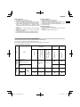
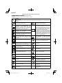
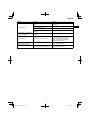
SELECTING CUTTING ATTACHMENTS
Recommended accessories for each model are presented in the table below.
For purchases, contact Hitachi Authorized Service Centers.
Please check carefully as those accessories not marked with “
●” cannot be attached.
List of recommended accessories
Type
Name
Specifi cation
LOOP
HANDLE
BIKE
HANDLE
Diameter
Feed System Adapter
or
No. of Teeth (Blade)
Blade Thickness (mm)
or
Trimmer line Diameter
(mm)
CG40EAS (LP)
CG40EAS (P)
ALUMINUM
HEADS
NYLON HEAD
CH-300
(W/CUTTER HOLDER
CAP)
5”
Manual line
feed
2.2 – 2.7
●●
NYLON HEAD
CH-300
●●
BLADES
BLADE
B3/10/2.01
10” 3 2.0 ●●
BLADE
B3/12/3.0
12” 3 3.0 ●●
Daily maintenance
○ Clean the exterior of the unit.
○ Check that the harness is undamaged.
○ Check the cutting attachment guard for damage or
cracks. Change the guard in case of impacts or cracks.
○ Check that the cutting attachment is properly centered,
sharp, and without cracks. An off -center cutting
attachment induces heavy vibrations that may damage
the unit.
○ Check that the cutting attachment nut is suffi ciently
tightened.
○ Make sure that the blade cover is undamaged and that it
can be securely fi tted.
○ Check that nuts and screws are suffi ciently tightened.
○ Check that the unit is undamaged and free of defects.
Weekly maintenance
○ Check the starter, especially the cord.
○ Clean the exterior of the spark plug.
○ Remove the spark plug and check the electrode gap.
Adjust it to 0.6 mm, or change the spark plug.
○ Check that the angle gear is fi lled with grease up to 3/4.
○ Clean the air fi lter.
Monthly maintenance
○ Rinse the fuel tank with gasoline.
○ Clean the exterior of the carburetor and the space
around it.
○ Clean the fan and the space around it.

English
14
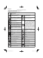
TROUBLESHOOTING
Use the inspections in the table below if the tool does not operate normally. If this does not remedy the problem, consult your
dealer or the Hitachi Authorized Service Center.
Condition Cause Remedy
Engine does not
start
Fuel
system
Fuel tank is empty or fuel level is low
Fill the fuel tank with the correct fuel mix
(25:1-50:1)
Fuel tank contains old fuel
(off ensive odor)
Replace with new fuel
Too much fuel is absorbed and spark
plug is wet
1. Disconnect the spark plug and allow to
dry
2. Pull the starter handle 5 or 6 times to
remove the surplus fuel
3. Attach the spark plug
4. Set the choke lever to RUN position and
pull the starter handle
Fuel fi lter is clogged with dirt Clean the fuel fi lter
Fuel pipe is bent or disconnected Ensure that the fuel fl ows smoothly
Carburetor malfunction Contact Hitachi Authorized Service Centers
Electrical
system
Stop switch lead has short-circuited Contact Hitachi Authorized Service Centers
Spark plug is dirty Replace or clean the spark plug
Electrode gap is too big Adjust the gap to 0.6mm
Poor connection between high tension
cable and spark plug
Reconnect
Electrical system malfunction Contact Hitachi Authorized Service Centers
Other
Muffl er exhaust port is clogged with
carbon
Contact Hitachi Authorized Service Centers
for repair
Engine starts
but cuts out
straightaway
Engine is apt to
cut out
Fuel
system
Fuel tank is empty or fuel level is low
Fill the fuel tank with the correct fuel mix
(25:1-50:1)
Fuel tank contains old fuel
(off ensive odor)
Replace with new fuel
Two-cycle oil has not been added Contact Hitachi Authorized Service Centers
Choke lever is in START position Set the choke lever to RUN position
Air has got into fuel system Reconnect the fuel pipe or joint
Carburetor malfunction Contact Hitachi Authorized Service Centers
Electrical
system
Ignition failure
Spark plug failure Replace with new spark plug
Electrical system failure Contact Hitachi Authorized Service Centers
Other
Engine overheating
Wrong spark plug model
Replace with designated part
See “SPECIFICATIONS”
Dirty air cleaner Clean
Carbon clogging (muffl er exhaust port) Clean
Insuffi cient compression (piston, piston
ring, cylinder)
Contact Hitachi Authorized Service Centers
Abnormal vibration
Cutting attachment is not properly
installed
See “Installation of cutting attachment”
Handle, handle bracket or other
fastening part is loose
Check and tighten
Blade is bent or damaged Replace with new blade
Grass is wrapped round gear case Remove grass
Engine is running but blade
does not move
Movement is poor
Grass is wrapped round gear case Remove grass and dirt

English
15
Condition Cause Remedy
Engine does not stop Stop switch failure
Set the choke lever to START position to
stop the engine
Cease use immediately and contact Hitachi
Authorized Service Centers
Engine stops when throttle is
closed
Idle speed is too low Contact Hitachi Authorized Service Centers
Blade continues rotating when
throttle is closed
Idle speed is too high
Throttle wire is too taut
Contact Hitachi Authorized Service Centers

Deutsch
16
(Übersetzung der Original-Gebrauchsanweisung)
SYMBOLBEDEUTUNGEN
HINWEIS: Nicht alle Geräte sind mit diesen Symbolen versehen.
Symbole
WARNUNG
Die folgenden Symbole werden für dieses Gerät verwendet. Achten Sie darauf, diese vor der Verwendung zu
verstehen.
Rasentrimmer / Heckenschere Garantierter Schallleistungspegel
Es ist wichtig, dass Sie sich mit den
nachfolgenden Vorsichtsmaßnahmen und
Warnungen vertraut machen und diese
befolgen. Unvorsichtige oder unsachgemäße
Handhabung des Geräts kann schwere oder
tödliche Verletzungen zur Folge haben.
Ein Messerstoß ist möglich, wenn das rotierende
Messer im kritischen Bereich mit einem massiven
Gegenstand in Berührung kommt. In diesem Fall
kann es zu einer gefährlichen Reaktion kommen,
bei der das gesamte Gerät und der Bediener
einem heftigen Stoß ausgesetzt werden.
Diese Reaktion wird als Messerstoß bezeichnet.
Das Resultat ist u.U., dass der Bediener die
Kontrolle über das Gerät verliert und schwere
oder lebensgefährliche Verletzungen davonträgt.
Messerstöße sind in Arbeitsbereichen, wo das
zu schneidende Vegetationsmaterial nur schwer
einsehbar ist, wahrscheinlicher.
Lesen, verstehen und befolgen Sie alle
Warnungen und Anweisungen in dieser
Anleitung und am Gerät selbst.
Bei Gebrauch des Geräts immer Gesichts-,
Kopf- und Gehörschutz tragen.
Halten Sie alle Kinder, Zuschauer und Helfer
15 m vom Gerät entfernt. Falls sich jemand
nähert, den Motor und das Zubehör sofort
ausschalten.
Heiße Oberfl äche – Kontakt mit heißer
Oberfl äche kann zu schweren Verbrennungen
führen.
Auf hochgeschleuderte Gegenstände achten.
Bezeichnet den Griff stangenplatz. Griff stange
nicht oberhalb dieses Punktes anbringen.
min
-1
Zeigt die maximale Drehzahl der Welle an.
Verwenden Sie kein Schneidzubehör, dessen
Maximaldrehzahl unter diesem Wert liegt.
Verschiebung
Handschuhe sind dann zu tragen, wenn
dies notwendig ist, z.B. bei der Montage der
Schneide-Ausrüstung.
Zündkerze
Rutschfestes Schuhwerk tragen, das guten Halt
bietet.
Idle
Leerlaufdrehzahl
Choke – Betriebsposition (Off en) Drehzahl der Ausgangswelle
Choke – Start Position (Geschlossen)
P
Max. Motorleistung
START
Ein/Start Kraftstoff tankvolumen
STOP
Aus/Stopp
Trockengewicht
(ohne Kraftstoff , Schneide-Zubehör, Gurtzeug
und Schutz-Schneide-Zubehör)
Kraftstoff -Öl-Gemisch Schneide-Zubehör
Einstellung des Leerlaufs
L
pA, eq
ISO22868
Schalldruckpegel LpA nach ISO 22868
Entsprechung*
Ansaugpumpe
L
WA, Ra(M)
2000/14/EC
Gemessener Schalldruck-Leistungspegel LwA
nach 2000/14/EC
Hochdrehen

Deutsch
17
L
WA, Ra(G)
2000/14/EC
Garantierter Schalldruck-Leistungspegel LwA
nach 2000/14/EC
Hochdrehen
a
hv, eq(R)
Vibrationspegel nach ISO 22867
Hinterer oder rechter Griff / Entsprechung*
a
hv, eq(F)
Vibrationspegel nach ISO 22867
Vorderer oder linker Griff / Entsprechung*
K
Unsicherheit
Vor dem Gebrauch Ihres Geräts
• Bedienungsanleitung sorgfältig durchlesen.
• Montage und Einstellung der Schneide-Ausrüstung kontrollieren.
• Gerät starten und Vergasereinstellung prüfen. Siehe „WARTUNG“.
HINWEIS: Die entsprechenden Geräusch- / Vibrationspegel werden als zeitgewichtete Energiesumme für Geräusch- /
Vibrationspegel unter verschiedenen Arbeitsbedingungen mit folgender Zeitaufteilung berechnet:
* 1/2 Leerlauf, 1/2 Hochgedreht.
WAS IST WAS? (Abb. 1)
Da dieses Handbuch für mehrere Modelle gilt, können die
Abbildungen gegebenenfalls von Ihrem Gerät abweichen.
Verwenden Sie die für Ihr Gerät geltenden Anweisungen.
A: Tankdeckel
B: Gaszug
C: Startergriff
D: Schutz Schneide-Zubehör
E: Schneide-Zubehör
F: Antriebswellenrohr
G: Griff
H: Aufhänger
I: Zündschalter
J: Gurtzeug
K: Gaszugsperre
L: Chokehebel
M: Motor
N: Getriebegehäuse
O: Kombischlüssel
P: Bedienungsanleitung
Q: Brille
R: Sechskantschlüssel
S: Klingenabdeckung (je nach Ausstattung)
T: Spanner
WARN- UND SICHERHEITSHINWEISE
Abschnitte, denen besondere Aufmerksamkeit gewidmet
werden sollte, werden durch folgende Wörter hervorgehoben:
WARNUNG
Kennzeichnet Anweisungen, deren Nichtbefolgung eine
schwere Verletzung oder den Tod zur Folge haben kann.
VORSICHT
Kennzeichnet Anweisungen, deren Nichtbefolgung eine
Verletzung oder Sachschaden zur Folge haben kann.
HINWEIS
Kennzeichnet nützliche Informationen für den
vorschriftsmäßigen Gebrauch.
Bedienersicherheit
○ Kopfschutz tragen (1). (Abb. 2)
○ Immer einen Gesichtsschutz oder Schutzbrille tragen
(2). (Abb. 2)
○ Vorschriftsmäßigen Gehörschutz tragen (3). (Abb. 2)
Über einen längeren Zeitraum Lärm ausgesetzt sein,
kann zu bleibenden Hörschäden führen.
Die Umgebung im Auge behalten. Auf Beistehende
achten, die unter Umständen ein Problem signalisieren.
Die Schutzbekleidung erst nach Abstellen des Motors
wieder ablegen.
○ Immer schwere, langärmlige Shirts tragen (4) und lange
Hosen (5) und rutschfeste Stiefel (6) und Handschuhe
(7). (Abb. 2)
Das Arbeiten mit lockerer Kleidung, Schmuck, kurzen
Hosen, Sandalen oder barfuß ist zu vermeiden.
Das Haar ist so zu sichern, dass es nicht bis zu den
Schultern herunterhängt.
○ Bedienen Sie das Gerät nicht, wenn Sie übermüdet
oder krank sind oder unter Alkohol-, Drogen- oder
Medikamenteneinfl uss stehen.
○ Bedienen Sie das Werkzeug nicht bei Nacht oder unter
schlechten Wetterbedingungen, wenn die Sicht schlecht
ist. Und bedienen Sie das Werkzeug nicht, wenn es
regnet oder unmittelbar, nachdem es geregnet hat.
Arbeiten auf rutschigem Untergrund kann zu einem
Unfall führen, wenn Sie Ihr Gleichgewicht verlieren.
○ Lassen Sie niemals ein Kind oder eine unerfahrene
Person die Maschine bedienen.
○ Starten Sie den Motor nicht, wenn leicht Entfl ammbares
wie trockenes Laub, Papierabfall oder Kraftstoff in der
Nähe sind.
○ Starten oder betreiben Sie denn Motor niemals innerhalb
geschlossener Räume oder in einem Gebäude.
Einatmen der Abgase kann den Tod zur Folge haben.
○ Halten Sie die Griff e frei von Öl und Kraftstoff .
○ Berühren Sie nicht die Schneide-Ausrüstung.
○ Fassen oder halten Sie das Gerät nicht an der
Schneideausrüstung.
○ Beim Anbau oder Entfernen der Schneide-Ausrüstung
sollten Handschuhe getragen werden. Wird dies nicht
beachtet, kann es zu Verletzungen kommen.
○ Wenn das Gerät ausgeschaltet wird, achten Sie darauf,
dass die Schneide-Ausrüstung gestoppt hat, bevor Sie
das Gerät auf den Boden stellen.
○ Bei längerem Betrieb regelmäßig eine Pause einlegen, als
vorbeugende Maßnahme gegen die Weißfi ngerkrankheit,
die durch Vibrationen verursacht wird.
WARNUNG
○ Bedienen Sie das Werkzeug immer mit geeigneter
Schutzausrüstung und -kleidung. Nichtbeachtung kann
zu Unfällen wie Verbrennungen und Verletzungen führen.
(Abb. 2)
○ Berühren Sie während des Betriebs nicht den Bereich
der Zündkerze oder Hochspannung. Dadurch könnte es
zu einem elektrischen Schlag kommen.
○ Gestatten Sie Kindern nicht, sich während des Betriebs
in der Nähe des Werkzeugs aufzuhalten.
○ Berühren Sie während oder kurz nach dem Betrieb
nicht den Auspuff , Schalldämpfer oder das Abgasventil.
Dadurch könnte es zu Verbrennungen oder Verletzungen
kommen.
○ Antivibrationssysteme sind kein garantierter Schutz gegen
die Weißfi ngerkrankheit oder Karpaltunnelsyndrom.
Daher ist bei regelmäßigem Dauereinsatz des Geräts
der Zustand von Fingern und Handwurzel aufmerksam
zu beobachten. Falls Symptome der obengenannten
Krankheiten auftreten, sofort einen Arzt aufsuchen.

Deutsch
18
○ Träger eines medizinischen elektrischen bzw.
elektronischen Geräts (Herzschrittmacher u. dgl.) sollten
sich vor dem Gebrauch eines Motorgeräts von Ihrem
Arzt sowie dem Hersteller des Geräts diesbezüglich
beraten lassen.
Geräte-/Maschinensicherheit
○ Das Gerät/die Maschine vor jedem Einsatz einer
eingehenden Kontrolle unterziehen. Beschädigte
Teile ersetzen. Das Gerät auf auslaufenden
Kraftstoff untersuchen und sicherstellen, dass alle
Befestigungsteile vorhanden und sicher angezogen
sind.
○ Ersetzen Sie Teile, die gerissen, gebrochen oder
anderweitig beschädigt sind, bevor Sie das Gerät/die
Maschine verwenden. Fehlerhafte Teile können das
Risiko von Unfällen erhöhen und zu einer Verletzung
führen.
○ Achten Sie darauf, dass der Schutz der Schneide-
Ausrüstung und das Gurtzeug korrekt befestigt sind.
Funktioniert nicht, wenn der Schutz der Schneide-
Ausrüstung und das Gurtzeug nicht korrekt befestigt
sind.
○ Halten Sie während der Vergasereinstellung andere
Personen fern.
○ Verwenden Sie nur Zubehör, das vom Hersteller für
dieses Gerät/diese Maschine empfohlen wurde.
○ Achten Sie vor der Inbetriebnahme darauf, dass keine
Werkzeuge wie der Einstellschlüssel oder Spanner noch
am Gerät befestigt sind.
WARNUNG
○ Bauen Sie das Gerät/die Maschine in keiner Weise um.
Das Gerät nur für die Zwecke verwenden, für die es
bestimmt ist.
○ Nichtautorisierter Umbau und/oder Zubehör können zu
schweren Verletzungen oder zum Tod des Bedieners
oder anderer Personen führen.
Kraftstoff sicherheit
○ Mischen und füllen Sie den Kraftstoff draußen ein, wo
sich keine Funken oder Flammen befi nden.
○ Verwenden Sie einen Behälter, der für Kraftstoff
zugelassen ist.
○ Gehen Sie mindestens 3 m von der Betankungsstelle
weg, bevor Sie den Motor starten.
○ Stoppen Sie den Motor, bevor Sie den Tankdeckel
entfernen. Entfernen Sie den Tankdeckel nicht während
des Betriebs.
○ Leeren Sie den Kraftstoff tank, bevor Sie das Gerät/die
Maschine einlagern. Es wird empfohlen, den Kraftstoff
nach jedem Einsatz abzulassen. Mit gefülltem Tank ist
das Gerät so zu lagern, dass kein Kraftstoff ausläuft.
WARNUNG
○ Kraftstoff ist leichtentzündlich oder kann explodieren
oder die Dämpfe eingeatmet werden, lassen Sie deshalb
besondere Sorgfalt walten, wenn Sie mit Kraftstoff
umgehen oder ihn einfüllen.
○ Rauchen Sie nicht und erlauben Sie anderen Personen
nicht das Rauchen in der Nähe des Geräts/der
Maschine oder während der Verwendung des Geräts/
der Maschine.
○ Wischen Sie vor dem Starten des Motors alle
Kraftstoff spritzer weg.
○ Gerät und Kraftstoff an einem Ort lagern, wo
Kraftstoff dämpfe nicht mit Funken oder off enen Flammen
von Wassererhitzern, Elektromotoren oder elektrischen
Schaltern, Öfen usw. in Berührung kommen können.
○ Wenn dieses Gerät in trockenen Bereichen verwendet
wird, achten Sie darauf, dass eine Feuerlöschausrüstung
bereit steht.
○ Wenn Sie den Motor zum Nachtanken abschalten,
lassen Sie das Gerät erst abkühlen, bevor Sie Kraftstoff
nachfüllen.
Schneidsicherheit
○ Schneiden Sie keine anderen Materialien außer Gras
und Hecken.
○ Inspizieren Sie vor jeder Verwendung den zu mähenden
Bereich.
Entfernen Sie Gegenstände, die hochgeschleudert
werden oder sich verfangen können.
Nicht in Bereichen mit Baumwurzeln oder Felsen
verwenden.
○ Tragen Sie zum Schutz der Atemwege eine Aerosol-
Schutzmaske, wenn Sie Gras schneiden, auf dem
Insektenvernichtungsmittel versprüht wurde.
○ Halten Sie andere Personen einschließlich Kinder,
Zuschauer und Helfer außerhalb der 15 m Gefahrenzone.
Den Motor sofort abstellen, wenn sich jemand nähert.
○ Seien Sie vorsichtig, da der Motorstart nach dem Ziehen
des Startgriff s verzögert auftreten kann.
○ Halten Sie den Motor immer auf Ihrer rechten
Körperseite.
○ Halten Sie das Gerät/die Maschine mit beiden Händen
fest.
○ Achten Sie auf sicheren Stand und Gleichgewicht. Nicht
zu weit vorbeugen.
Wenn Sie während der Arbeit das Gleichgewicht
verlieren, kann das zu einer Verletzung führen.
○ Halten Sie alle Körperteile vom Schalldämpfer und der
Schneide-Ausrüstung entfernt, wenn der Motor läuft.
○ Halten Sie die Schneide-Ausrüstung unterhalb Ihrer
Knie.
○ Seien Sie besonders vorsichtig beim Betrieb in
Bereichen mit Elektrokabeln oder Gasleitungen.
○ Verwenden Sie die Schneide-Ausrüstung nicht für
etwas anderes außer zum Schneiden von Gras oder
Hecken. Vermeiden Sie den Betrieb, wenn die Schneide-
Ausrüstung Wasser, wie Pfützen berühren oder sich in
die Erde eingraben könnte. Nichtbeachtung kann zu
Verletzungen oder Beschädigung des Geräts führen.
○ Vermeiden Sie längeren Betrieb bei niedriger Drehzahl,
bei der die Vibrationen stark sind. Dadurch kann es zu
einem Motorschaden kommen.
○ Beim Wechsel in einen anderen Arbeitsbereich oder
Inspektion, Einstellung oder Austausch der Schneide-
Ausrüstung, Zubehör, usw. des Geräts, achten Sie
darauf, dass die Maschine ausgeschaltet ist und alle
Schneide-Ausrüstungen gestoppt haben.
○ Stellen Sie die Maschine niemals auf den Boden,
während sie läuft.
○ Berühren Sie niemals die Schneide-Ausrüstung,
während sie sich dreht.
○ Achten Sie immer darauf, dass der Motor ausgeschaltet
ist und die Schneide-Ausrüstung komplett gestoppt
ist, bevor Sie Schmutz oder Gras von der Schneide-
Ausrüstung entfernen.
○ Führen Sie bei Arbeiten mit Motorgeräten immer einen
Verbandkasten mit.
○ Schalten Sie den Motor aus und achten Sie darauf,
dass die Schneide-Ausrüstung vollständig gestoppt hat,
bevor Sie das Gerät von Ihrem Körper entfernen oder
unbeaufsichtigt lassen.
○ Wenn Sie das Gerät versehentlich anstoßen oder fallen
lassen, inspizieren Sie es sofort, um sicherzustellen,
dass keine Beschädigung, Risse oder Verformungen
vorliegen.
○ Wenn das Werkzeug schlechte Leistung zeigt und
anomale Geräusche oder Vibrationen auftreten, schalten
Sie den Motor sofort aus und lassen Sie es von Ihrem
Händler überprüfen und reparieren.
Eine weitere Verwendung unter diesen Bedingungen
kann zu Verletzungen oder Beschädigung des
Werkzeugs führen.
○ Verwendung nur in Übereinstimmung mit den lokalen
Gesetzen und Richtlinien.

Deutsch
19
WARNUNG
RÜCKSCHLAGGEFAHR (Abb. 3)
Bei Verwendung von Schneide-Ausrüstung aus Metall,
wie Klingen, kann der Kontakt mit Hindernissen wie
Bäumen oder anderen harten Oberfl ächen mit der
Vorderseite oder rechten Seite der Drehvorrichtung dazu
führen, dass sich das Gerät am Hindernis verfängt, was
zu einer Rückschlagsreaktion zur rechten Seite des
Bedieners führt.
Rückschlag kann auftreten, wenn die Schneide-
Ausrüstung Baumstümpfe oder Felsen berührt, die hinter
Gebüsch verborgen sind. Achten Sie immer darauf, dass
keine Hindernisse von Gebüsch verdeckt werden, bevor
Sie mit der Arbeit beginnen.
Um die Gefährlichkeit von Rückschlägen zu minimieren,
wenn sie auftreten, positionieren Sie das Gerät während
des Betriebs immer an Ihrer rechten Körperseite. Ist
der Bediener in der korrekten Position, während die
Schneide-Ausrüstung sich dreht, verringert das die
Gefahr einer direkten Berührung des Geräts mit dem
Körper.
Wartungssicherheit
○ Warten Sie das Gerät/die Maschine gemäß den
empfohlenen Verfahren.
○ Ziehen Sie vor der Durchführung von Wartungsarbeiten
außer der Vergasereinstellung den Zündkerzenstecker
ab.
○ Halten Sie andere Personen entfernt, wenn Sie
Vergasereinstellungen durchführen.
○ Verwenden Sie nur original HITACHI-Ersatzteile, die vom
Hersteller empfohlen werden.
VORSICHT
Den Zugstarter (Anwerfvorrichtung) nicht zerlegen. Die
in der Vorrichtung gespannte Feder kann Verletzungen
verursachen.
WARNUNG
Fehlerhafte Wartung kann eine schwere Beschädigung
des Motors oder eine schwere Verletzung zur Folge
haben.
Transport und Lagerung
○ Tragen Sie das Gerät/die Maschine nur mit
angehaltenem Motor und dem Schalldämpfer von Ihrem
Körper entfernt.
○ Lassen Sie den Motor abkühlen, leeren Sie den
Kraftstoff tank und sichern Sie das Gerät/die Maschine
vor der Lagerung oder dem Transport. Nichtbeachtung
kann zu Feuer oder Unfällen führen.
○ Leeren Sie den Kraftstoff tank, bevor Sie das Gerät/die
Maschine einlagern. Es wird empfohlen, den Kraftstoff
nach jedem Einsatz abzulassen. Mit gefülltem Tank ist
das Gerät so zu lagern, dass kein Kraftstoff ausläuft.
○ Lagern Sie das Gerät/die Maschine außerhalb der
Reichweite von Kindern.
○ Reinigen und warten Sie das Gerät sorgfältig und lagern
Sie es an einem trockenen Ort.
○ Achten Sie beim Transport oder der Lagerung darauf,
dass der Motorschalter ausgeschaltet ist.
○ Entfernen Sie zum Transport oder zur Lagerung
entweder die Schneide-Ausrüstung oder befestigen Sie
den Klingenschutz über der Klinge.
○ Sie müssen die Maschine während des Transports so
sichern, dass Verlust von Kraftstoff , Beschädigung oder
Verletzungen vermieden werden.
○ Wenn ein Warnschild unleserlich ist, sich ablöst oder
verwischt, ersetzen Sie es durch ein neues. Zum Erwerb
von neuen Aufklebern wenden Sie sich an von Hitachi
autorisierte Servicecenter.
In Situationen, die nicht in dieser Anleitung behandelt sind,
entsprechende Vor- und Umsicht walten lassen. Sollten
Sie Hilfe benötigen, wenden Sie sich an eine von Hitachi
autorisierte Service-Werkstatt.
TECHNISCHE DATEN
Die TECHNISCHEN DATEN dieser Maschine sind in der
Tabelle auf Seite 119 aufgelistet.
HINWEIS
Änderungen der technischen Daten jederzeit vorbehalten.
ZUSAMMENBAU
Montage des Handgriff s
(1) Schleifengriff -Typ (Abb. 4)
Den Handgriff zum Motor geneigt an das
Antriebswellenrohr anbringen.
Den Handgriff vor der Inbetriebnahme auf eine
komfortable Position einstellen.
Achten Sie darauf, den Griff mit den 2 Schrauben sicher
zu befestigen.
HINWEIS
Falls auf dem Antriebswellenrohr Ihres Geräts ein Schild
mit Informationen zur Handgriff position (8) angebracht
ist, halten Sie sich an die Darstellung.
(2) Fahrradlenker-Typ (Abb. 5)
Den Griff halter (9) von der Einheit entfernen.
Den Griff einsetzen und den Griff halter mit vier
Schrauben locker befestigen. Den Winkel je nach Bedarf
ausrichten. Dann die Schrauben festziehen.
Das Schutzrohr mit Hilfe von Kabelklemmen (10) an der
Antriebswelle oder dem Griff befestigen. (Abb. 6)
Montage des Gurtzeugs
WARNUNG
Wenn das Produkt ein Gurtzeug enthält, verwenden Sie
dieses immer.
Befestigen Sie den Haken des Gurtzeugs (11) am
Aufhänger (12) am Rohr der Antriebswelle. (Abb. 7)
Passen Sie die Länge des Gurtzeugs so an, dass sich das
Werkzeug leicht bedienen lässt.
HINWEIS
Möglicherweise müssen Sie die Position des Aufhängers
(12) anpassen, um das Gerät auszubalancieren.
Lösen Sie dafür die Schraube (13) und passen Sie die
Position des Aufhängers (12) an. Achten Sie nach der
notwendigen Anpassung darauf, die Schraube (13) fest
anzuziehen. (Abb. 7)
Installation des Schutzes der Schneide-Ausrüstung
WARNUNG
Wenn ein falscher oder fehlerhafter Schutz angebaut
wird, kann es zu schweren Verletzungen kommen.
VORSICHT
Manche Schutzvorrichtungen der Schneide-Ausrüstung
sind mit einem Scharfkantenschutz ausgestattet. Gehen
Sie vorsichtig damit um.
HINWEIS
Bei einigen Modellen wird das Getriebegehäuse bereits
mit montierten Schutzhalter geliefert.
Richten Sie den Schutz der Schneide-Ausrüstung mit dem
Schutzhalter aus und befestigen Sie ihn mit der Schraube
und Abdeckungshalterung am Rohr der Antriebswelle.
(Abb. 8)

Deutsch
20
Installation der Schneide-Ausrüstung
WARNUNG
○ Montieren Sie die Schneide-Ausrüstung korrekt und
sicher wie in den Bedienungsanleitungen beschrieben.
Bei falscher oder nicht sicherer Befestigung kann sie
sich lösen und ernste und/oder tödliche Verletzungen
verursachen.
○ Montieren oder entfernen Sie die Schneide-
Ausrüstungen nicht, während der Motor läuft.
○ Verwenden Sie immer Hitachi Schneide-Ausrüstungen
und Metall-Befestigungen.
Anbringung des halbautomatischen Schneidkopfs
1. Funktion
Durch Tippen des Schneidkopfs auf den Boden bei
geringer Drehzahl (weniger als 4500 U/min) wird der zur
Verfügung stehende Nylonfaden automatisch verlängert.
Verwendbarer Nylonfaden
Fadendurchmesser Φ2,5 mm
2. Vorsichtsmaßnahmen
○ Das Gehäuse muss fest an der Abdeckung angebracht
sein.
○ Abdeckung, Gehäuse und andere Komponenten auf
Risse oder andere Beschädigungen überprüfen.
○ Gehäuse und Knopf auf Verschleiß überprüfen.
○ Der Schneidkopf muss fest auf dem Getriebegehäuse/
Schneidegehäuse des Geräts angebracht sein.
○ Wenn die Schneidfadenbereitstellung durch den
Schneidkopf nicht ordnungsgemäß funktioniert,
die korrekte Anbringung des Nylonfadens und aller
Komponenten kontrollieren. Sollten Sie Hilfe benötigen,
wenden Sie sich an eine von Hitachi autorisierte Service-
Werkstatt.
WARNUNG
Für Schneidköpfe von Hitachi dürfen nur die vom
Hersteller empfohlenen fl exiblen, nicht metallischen
Züge verwendet werden. Metalldrähte oder Drahtseile
sind keinesfalls zulässig. Sie könnten reißen und zu
einem gefährlichen Geschoss werden.
3. Installation (Abb. 9)
Den Inbusschlüssel (14) in die Öff nung des
Getriebegehäuses/Schneidegehäuses einführen und
das Rohr der Antriebswelle verriegeln.
Den Schneidekopf am Getriebegehäuse/
Schneidegehäuse des Rasentrimmers/der Heckenschere
installieren. Die Befestigungsschraube ist mit einem
Linksgewinde versehen. Zum Lösen im Uhrzeigersinn
drehen/zum Festziehen gegen den Uhrzeigersinn drehen.
HINWEIS
Die Messerhaltekappe, die hier nicht benötigt wird, für
den Einsatz mit einem Metallmesser, falls vorhanden,
aufbewahren.
4. Fadenlänge einstellen
Eine möglichst geringe Motordrehzahl wählen und mit
dem Gerätekopf auf den Boden tippen. Mit jedem Tippen
verlängert sich der Nylonfaden um ca. 3 cm. (Abb. 10)
Der Nylonfaden kann auch von Hand ausgezogen
werden, der Motor muss allerdings vollkommen zum
Stillstand gekommen sein. (Abb. 11)
Den Nylonfaden vor jeder Verwendung des Geräts auf
die korrekte Länge von 11-14 cm einstellen.
Montage des Schneidmessers (Abb. 12)
○ Achten Sie bei der Montage der Mutternabdeckung (17)
darauf, dass die konkave Seite nach oben weist.
○ Setzen Sie den Inbusschlüssel (14) in das Loch
auf dem Getriebegehäuse ein, um den Schneider-
Halter (A) (15) zu verriegeln. Ziehen Sie die
Befestigungsmutter (19) mit dem Kombi-Steckschlüssel
mit einem Anzugsdrehmoment von 22 ± 2 N.m fest.
Es ist zu beachten, dass die Befestigungsmutter über
ein Linksgewinde verfügt (Lösen im Uhrzeigersinn,
Anziehen gegen den Uhrzeigersinn).
○ Wenn Ihr Gerät eine Befestigung mit Mutter hat und mit
einem Splint ausgestattet ist, muss das Messer bei jeder
Installation mit einem neuen Splint (20) befestigt werden.
(Abb. 13)
HINWEIS
Achten Sie bei der Montage oder dem Entfernen
einer Klinge darauf, Handschuhe zu tragen und den
Klingenschutz über der Klinge zu befestigen.
VORSICHT
Überprüfen Sie die Mutter-Abdeckung (17) vor
dem Betrieb auf Verschleiß oder Risse. Wenn
Beschädigungen oder Spuren von Abnutzung zu sehen
sind, tauschen Sie sie aus, denn es handelt sich um ein
Verschleißteil.
WARNUNG
○ Bei der Montage eines Schneidmessers darauf achten,
dass es keine Risse oder Beschädigungen aufweist und
die Schneidkanten richtig ausgerichtet sind.
○ Entfernen Sie allen Schmutz von den Oberfl ächen
der Befestigungsmaterialien (Schneider-Halter (A)
(15), Schneider-Halter (B) (16), Mutternabdeckung
(17), Unterlegscheibe (18), Mutter (19), Stift (20)).
Nichtbeachtung kann dazu führen, dass die Muttern sich
lösen.
○ Der Vorsprung am Schneidehalter (A) (15) kann sich aus
der Ausrichtung mit der Klinge verschieben, während
die Mutter (19) angezogen wird. Vor der Inbetriebnahme
überprüfen, ob das Messer ordnungsgemäß montiert ist.
(Abb. 14)
○ Drehen Sie die Klinge von Hand und achten Sie darauf,
dass kein Ruckeln oder anomale Geräusche auftreten.
Ruckeln kann zu anomalen Vibrationen führen oder
dazu, dass die Muttern sich lösen.
VORSICHT
○ Vor der Inbetriebnahme überprüfen, ob das Messer
ordnungsgemäß montiert ist.
○ Wenn Ihr Gerät mit einer Schutzabdeckung unter dem
Schneidmesser ausgestattet ist, überprüfen Sie es
vor dem Einsatz auf Abnutzung oder Risse. Wenn
Beschädigungen oder Spuren von Abnutzung zu sehen
sind, tauschen Sie es aus, denn es handelt sich um ein
Verschleißteil.
○ Beim Handhaben der Schneideklinge müssen Sie
Handschuhe tragen.
WARNUNG
Benutzen Sie für Hitachi-Köpfe nur vom Hersteller
empfohlene fl exible, nicht metallische Züge. Metalldrähte
oder Drahtseile sind keinesfalls zulässig. Sie könnten
reißen und zu einem gefährlichen Geschoss werden.
BETRIEBSVERFAHREN
Kraftstoff (Abb. 15)
WARNUNG
○ Der Trimmer ist mit einem Zweitaktmotor ausgestattet.
Der Motor muss daher immer mit Kraftstoff -Ölgemisch
betrieben werden.
Beim Handhaben von und Auftanken mit Kraftstoff ist
stets für gute Belüftung zu sorgen.
○ Kraftstoff ist stark entfl ammbar und kann bei Einatmen
oder Hautkontakt schwere Verletzungen verursachen.
Kraftstoff stets mit der gebotenen Umsicht handhaben.
Bei der Handhabung von Kraftstoff in Gebäuden immer
auf gute Belüftung achten.
Strona się ładuje...
Strona się ładuje...
Strona się ładuje...
Strona się ładuje...
Strona się ładuje...
Strona się ładuje...
Strona się ładuje...
Strona się ładuje...
Strona się ładuje...
Strona się ładuje...
Strona się ładuje...
Strona się ładuje...
Strona się ładuje...
Strona się ładuje...
Strona się ładuje...
Strona się ładuje...
Strona się ładuje...
Strona się ładuje...
Strona się ładuje...
Strona się ładuje...
Strona się ładuje...
Strona się ładuje...
Strona się ładuje...
Strona się ładuje...
Strona się ładuje...
Strona się ładuje...
Strona się ładuje...
Strona się ładuje...
Strona się ładuje...
Strona się ładuje...
Strona się ładuje...
Strona się ładuje...
Strona się ładuje...
Strona się ładuje...
Strona się ładuje...
Strona się ładuje...
Strona się ładuje...
Strona się ładuje...
Strona się ładuje...
Strona się ładuje...
Strona się ładuje...
Strona się ładuje...
Strona się ładuje...
Strona się ładuje...
Strona się ładuje...
Strona się ładuje...
Strona się ładuje...
Strona się ładuje...
Strona się ładuje...
Strona się ładuje...
Strona się ładuje...
Strona się ładuje...
Strona się ładuje...
Strona się ładuje...
Strona się ładuje...
Strona się ładuje...
Strona się ładuje...
Strona się ładuje...
Strona się ładuje...
Strona się ładuje...
Strona się ładuje...
Strona się ładuje...
Strona się ładuje...
Strona się ładuje...
Strona się ładuje...
Strona się ładuje...
Strona się ładuje...
Strona się ładuje...
Strona się ładuje...
Strona się ładuje...
Strona się ładuje...
Strona się ładuje...
Strona się ładuje...
Strona się ładuje...
Strona się ładuje...
Strona się ładuje...
Strona się ładuje...
Strona się ładuje...
Strona się ładuje...
Strona się ładuje...
Strona się ładuje...
Strona się ładuje...
Strona się ładuje...
Strona się ładuje...
Strona się ładuje...
Strona się ładuje...
Strona się ładuje...
Strona się ładuje...
Strona się ładuje...
Strona się ładuje...
Strona się ładuje...
Strona się ładuje...
Strona się ładuje...
Strona się ładuje...
Strona się ładuje...
Strona się ładuje...
Strona się ładuje...
Strona się ładuje...
Strona się ładuje...
Strona się ładuje...
Strona się ładuje...
Strona się ładuje...
Strona się ładuje...
Strona się ładuje...
-
 1
1
-
 2
2
-
 3
3
-
 4
4
-
 5
5
-
 6
6
-
 7
7
-
 8
8
-
 9
9
-
 10
10
-
 11
11
-
 12
12
-
 13
13
-
 14
14
-
 15
15
-
 16
16
-
 17
17
-
 18
18
-
 19
19
-
 20
20
-
 21
21
-
 22
22
-
 23
23
-
 24
24
-
 25
25
-
 26
26
-
 27
27
-
 28
28
-
 29
29
-
 30
30
-
 31
31
-
 32
32
-
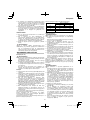 33
33
-
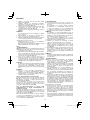 34
34
-
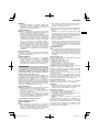 35
35
-
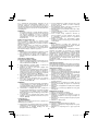 36
36
-
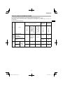 37
37
-
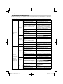 38
38
-
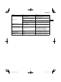 39
39
-
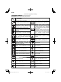 40
40
-
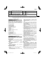 41
41
-
 42
42
-
 43
43
-
 44
44
-
 45
45
-
 46
46
-
 47
47
-
 48
48
-
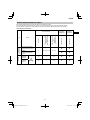 49
49
-
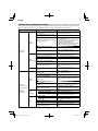 50
50
-
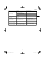 51
51
-
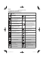 52
52
-
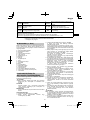 53
53
-
 54
54
-
 55
55
-
 56
56
-
 57
57
-
 58
58
-
 59
59
-
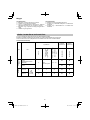 60
60
-
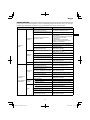 61
61
-
 62
62
-
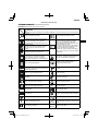 63
63
-
 64
64
-
 65
65
-
 66
66
-
 67
67
-
 68
68
-
 69
69
-
 70
70
-
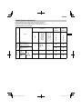 71
71
-
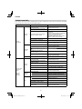 72
72
-
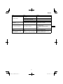 73
73
-
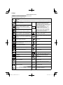 74
74
-
 75
75
-
 76
76
-
 77
77
-
 78
78
-
 79
79
-
 80
80
-
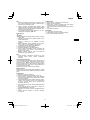 81
81
-
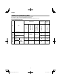 82
82
-
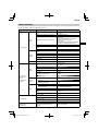 83
83
-
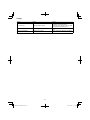 84
84
-
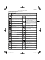 85
85
-
 86
86
-
 87
87
-
 88
88
-
 89
89
-
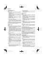 90
90
-
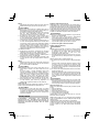 91
91
-
 92
92
-
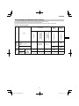 93
93
-
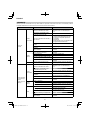 94
94
-
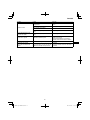 95
95
-
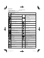 96
96
-
 97
97
-
 98
98
-
 99
99
-
 100
100
-
 101
101
-
 102
102
-
 103
103
-
 104
104
-
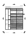 105
105
-
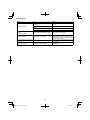 106
106
-
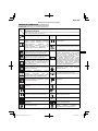 107
107
-
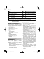 108
108
-
 109
109
-
 110
110
-
 111
111
-
 112
112
-
 113
113
-
 114
114
-
 115
115
-
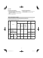 116
116
-
 117
117
-
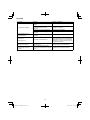 118
118
-
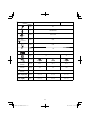 119
119
-
 120
120
-
 121
121
-
 122
122
-
 123
123
-
 124
124


Hitachi CG 40EAS (P) Handling Instructions Manual
- Typ
- Handling Instructions Manual
- Niniejsza instrukcja jest również odpowiednia dla
w innych językach
- slovenčina: Hitachi CG 40EAS (P)
- Türkçe: Hitachi CG 40EAS (P)
- română: Hitachi CG 40EAS (P)
Powiązane artykuły
-
Hitachi CG 40EAS P Handling Instructions Manual
-
Hitachi CG 33EJ (L) Instrukcja obsługi
-
-
-
-
-
-
-
Hitachi CH 22EC278ST Handling Instructions Manual
-