
Grass Trimmer/Brush Cutter
Rasentrimmer/Motorsense
Χλοοκοπτικό/Θαμνοκοπτικό
Podkaszarka/Kosa spalinowa
Benzinmotoros fűkasza/
Benzinmotoros bozótvágó
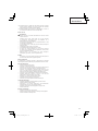
Read the manual carefully before operating this machine.
Lesen Sie vor der Verwendung diese Anleitung sorgfältig durch.
Διαβάστε προσεκτικά το εγχειρίδιο πριν χειριστείτε αυτό το μηχάνημα.
Przed uruchomieniem maszyny należy dokładnie przeczytać podręcznik.
Mielőtt a gépet használatba venné, gondosan olvassa el a használati utasítást.
Před použitím přístroje si návod pozorně přečtěte.
Makineyi çalıştırmadan önce kullanım kılavuzunu dikkatlice okuyun.
Citiţi cu atenţie prezentele instrucţiuni înainte de utilizarea maşinii.
Pred uporabo naprave pozorno preberite navodila.
Перед эксплуатацией этой машины внимательно прочтите руководство.
Handling instructions
Bedienungsanleitung
Οδηγίες χειρισμού
Instrukcja obsługi
Kezelési utasítás
Návod k obsluze
Kullanım talimatları
Instrucţiuni de utilizare
Navodila za rokovanje
Инструция по эксплуатации
Dostřihovač trávy/Křovinořez
Çim kesicisi/Çalı kesicisi
Trimmer gazon/Motocoasa
Motorna kosa/Motorna kosa
Травокосилка/Триммер
CG 25EUS/CG 25EUS (L)
CG25EUS(L)

2
6
4
5
8
11
7
10
9
3
2
1
123
456
7910
8

3
15 m
21
20
13
15
14
12
19
RUN
START
16
18
15
17
11 12 13
14 15 16
17 18 19
20 21 22

4
22
25
26
23
24
10 cm
25
10 cm
10 cm
0.6 mm
T
19
23 24 25
26 27 28
29 30 31
32 33 34

5
11–14 cm
11–14 cm
27
35 36

6
English
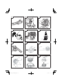
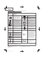
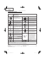
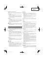
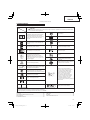
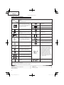
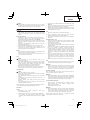
MEANINGS OF SYMBOLS
NOTE: Some units do not carry them.
Symbols
WARNING
The following show symbols used for the machine. Be sure that you understand their meaning before use.
It is important that you read, fully
understand and observe the following
safety precautions and warnings. Careless
or improper use of the unit may cause
serious or fatal injury.
Off /Stop
Emergency stop
Read, understand and follow all warnings
and instructions in this manual and on
the unit.
Engine oil fi ll
Fuel fi ll
Always wear eye, head and ear protectors
when using this unit.
Idle speed adjustment
Do not use metal/rigid blades when this
sign is shown on the unit.
Priming pump
Keep all children, bystanders and helpers
15 m away from the unit. If anyone
approaches you, stop the engine and
cutting attachment immediately.
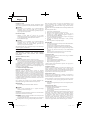
4
Guaranteed Sound power level
Be careful of thrown objects.
Hot surface – Contact with hot surface
can cause serious burns.
min
-1
Shows maximum shaft speed. Do not use
the cutting attachment whose max rpm is
below the shaft rpm.
The hedge trimmer attachment cannot
be used on models with this label.
Gloves should be worn when necessary,
e.g., when assembling cutting equipment.
Blade thrust may occur when the
spinning blade contacts a solid object
in the critical area. A dangerous
reaction may occur causing the entire
unit and operator to be thrust violently.
This reaction is called blade thrust. As
a result, the operator may lose control
of the unit which may cause serious or
fatal injury. Blade thrust is more likely
to occur in areas where it is diffi cult to
see the material to be cut.
Use anti-slip and sturdy footwear.
Choke - Run position (Open)
Choke - Start position (Closed)
On/Start
Indicate handle location. Do not attach
handle above this point.
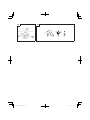
Before using your machine
• Read the manual carefully.
• Check that the cutting equipment is correctly assembled and adjusted.
• Start the unit and check the carburetor adjustment. See “MAINTENANCE”.
Contents
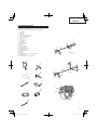
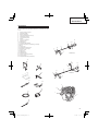
WHAT IS WHAT .................................................................................7
WARNINGS AND SAFETY INSTRUCTIONS ...................................8
SPECIFICATIONS .............................................................................9
ASSEMBLY PROCEDURES ..............................................................9
(Original instructions)
OPERATING PROCEDURES ..........................................................10
MAI NT ENA NCE ...............................................................................11
TROUBLE SHOOTING .....................................................................14

7
English
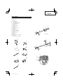
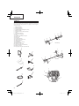
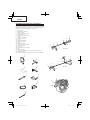
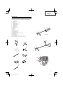
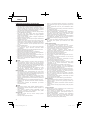
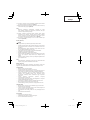
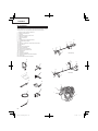
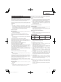
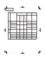
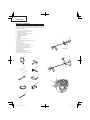
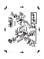
WHAT IS WHAT
Since this manual covers several models, there may be some
diff erence between pictures and your unit. Use the instructions that
apply to your unit.
1. Fuel cap
2. Throttle trigger
3. Starter handle
4. Cutting attachment guard
5. Cutting attachment
6. Drive shaft tube
7. H andle
8. Suspension eyelet
9. Ignition switch
10. Harness
11. Throttle trigger lockout
12. Choke lever
13. Engine
14. Angle transmission
15. Combi box spanner
16. Handling instructions
17. Oil cap
18. Hex. bar wrench
19. Spanner
20. Goggles
21. Blade cover (if so equipped)
22. Swivel cap
23. Cord clump (if so equipped)
14
6
7
5
4
2
13
9
11
9
11
13
8
2
7
6
14
5
4
3
12
1
17
CG25EUS (L)
CG25EUS
18
19
20
21
22
23
16
10
15

8
English
WARNINGS AND SAFETY INSTRUCTIONS
Operator safety
○ Always wear a safety face shield or goggles.
○ Always wear heavy, long pants, non-slip boots, gloves and
a long sleeve shirt. Do not wear loose clothing, jewelry, short
pants, sandals or go barefoot. Secure hair so it is above
shoulder length.
○ Do not operate this tool when you are tired, ill or under the
infl uence of alcohol, drugs or medication.
○ Do not operate the tool at night or under bad weather conditions
when visibility is poor. And do not operate the tool when it is
raining or right after it has been raining.
Working on slippery ground could lead to an accident if you
lose your balance.
○ Never let a child or inexperienced person operate the machine.
○ Long-term exposure to noise can result in permanent hearing
impairment. Wear approved hearing protection. Pay attention
to your surroundings. Be aware of any bystanders who may be
signaling a problem. Remove safety equipment immediately
upon shutting off engine.
○ Wear head protection.
○ Never start or run the engine inside a closed room or building.
Breathing exhaust fumes can kill.
○ Keep handles free of oil and fuel.
○ Keep hands away from cutting equipment.
○ Do not grab or hold the unit by the cutting equipment.
○ Gloves should be worn when installing or removing the cutting
attachment. Failure to do so may result in injury.
○ When the unit is turned off , make sure the cutting attachment
has stopped before the unit is set down.
○ When operation is prolonged, take a break from time to time
so that you may avoid possible Hand-Arm Vibration Syndrome
(HAVS) which is caused by vibration.
WARNING
○ Antivibration systems do not guarantee that you will not sustain
Hand-Arm Vibration Syndrome or carpal tunnel syndrome.
Therefore, continual and regular users should monitor closely
the condition of their hands and fi ngers. If any symptoms of the
above appear, seek medical advice immediately.
○ If you are using any medical electric/electronic devices such
as a pacemaker, consult your physician as well as the device
manufacturer prior to operating any power equipment.
Unit/machine safety
○ Inspect the entire unit/machine before each use. Replace
damaged parts. Check for fuel leaks and make sure all
fasteners are in place and securely tightened.
○ Replace parts that are cracked, chipped or damaged in any
way before using the unit/machine. Faulty parts may increase
the risk of accidents and may lead to an injury.
○ Make sure the safety guard is properly attached.
○ Keep others away when making carburetor adjustments.
○ Use only accessories as recommended for this unit/machine by
the manufacturer.
WARNING
○ Never modify the unit/machine in any way. Do not use your unit/
machine for any job except that for which it is intended.
○ Non-authorized modifi cations and/or accessories may result in
serious personal injury or the death of the operator or others.
Fuel safety
○ Mix and pour fuel outdoors and where there are no sparks or
fl ames.
○ Use a container approved for fuel.
○ Do not smoke or allow smoking near fuel or the unit/machine or
while using the unit/machine.
○ Wipe up all fuel spills before starting engine.
○ Move at least 3 m away from fueling site before starting engine.
○ Stop engine before removing fuel cap.
○ Empty the fuel tank before storing the unit/machine. It is
recommended that the fuel be emptied after each use. If fuel is
left in the tank, store so fuel will not leak.
○ Store unit/machine and fuel in area where fuel vapors cannot
reach sparks or open fl ames from water heaters, electric
motors or switches, furnaces. etc.
WARNING
Fuel is easy to ignite or get explosion or inhale fumes, so that
pay special attention when handling or fi lling fuel.
Cutting safety
○ Do not cut any material other than grass and brush.
○ Inspect the area to be cut before each use. Remove objects
which can be thrown or become entangled.
○ For respiratory protection, wear an aerosol protection mask
when cutting the grass after insecticide is scattered.
○ Keep others including children, animals, bystanders and
helpers outside the 15 m hazard zone. Stop the engine
immediately if you are approached.
○ Always keep the engine on the right side of your body.
○ Hold the unit/machine fi rmly with both hands.
○ Keep fi rm footing and balance. Do not over-reach.
Losing your balance during work may lead to an injury.
○ Keep all parts of your body away from the muffl er and cutting
attachment when the engine is running.
○ Keep cutting attachment below knee level.
○ When relocating to a new work area, be sure to shut off the
machine and ensure that all cutting attachments are stopped.
○ Never place the machine on the ground when running.
○ Always ensure that the engine is shut off and any cutting
attachments have completely stopped before clearing debris or
removing grass from the cutting attachment.
○ Always carry a fi rst-aid kit when operating any power
equipment.
○ Never start or run the engine inside a closed room or building
and/or near infl ammable liquids. Breathing exhaust fumes can
kill.
○ If the tool is operating poorly and produces strange noise or
vibrations, turn off the engine immediately and ask your dealer
to have it inspected and repaired.
Continued use under these conditions could lead to injury or
tool damage.
○ Use in accordance with local laws and regulations.
Maintenance safety
○ Maintain the unit/machine according to recommended
procedures.
○ Disconnect the spark plug before performing maintenance
except for carburetor adjustments.
○ Keep others away when making carburetor adjustments.
○ Use only genuine Hitachi replacement parts as recommended
by the manufacturer.
Transport and storage
○ Carry the unit/machine by hand with the engine stopped and
the muffl er away from your body.
○ Allow the engine to cool, empty the fuel tank, and secure the
unit/machine before storing or transporting.
○ Empty the fuel tank before storing the unit/machine. It is
recommended that the fuel be emptied after each use. If fuel is
left in the tank, store so fuel will not leak.
○
Store unit/machine out of the reach of children.
○ Clean and maintain the unit carefully and store it in a dry place.
○ Make sure engine switch is off when transporting or storing.
○ When transporting and storing, cover blade with blade cover.
○ You have to secure the machine during transport to prevent
loss of fuel, damage or injury.
If situations occur which are not covered in this manual, take care
and use common sense. Contact Hitachi Authorized Service
Centers if you need assistance. Pay special attention to statements
preceded by the following words:
WARNING
Indicates a strong possibility of severe personal injury or loss of
life, if instructions are not followed.

9
English
CAUTION
Indicates a possibility of personal injury or equipment damage,
if instructions are not followed.
NOTE
Helpful information for correct function and use.
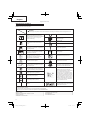
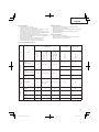
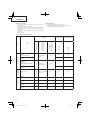
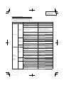
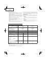
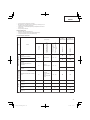
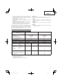
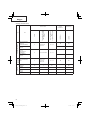
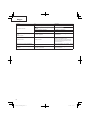
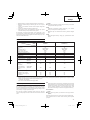
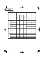
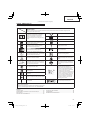
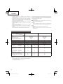
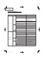
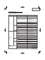
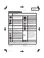
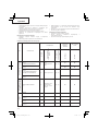
NOTE
Equivalent noise level/vibration level are calculated as the time-weighted energy total for noise/vibration levels under various working
conditions with the following time distribution:
* : 1/2 Idle, 1/2 racing
All data subject to change without notice.
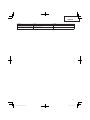
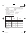
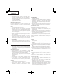
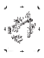
ASSEMBLY PROCEDURES
Drive shaft to engine (Fig. 1)
Loosen tube locking bolt (1) so that the bolt point will not obstruct
drive shaft tube to be inserted. When inserting drive shaft tube,
hold the tube locking bolt outward preventing inside fi tting from
obstructing as well.
Insert the drive shaft into the clutch case of the engine properly until
the marked position (2) on the drive shaft tube meets the clutch
case.
NOTE
When it is hard to insert drive shaft up to the marked position on
the drive shaft tube, turn drive shaft by the cutter mounting end
clockwise or counter-clockwise. Tighten tube locking bolt lining
up the hole in the shaft tube. Then tighten clamp bolt securely (3).
Installation of handle
WARNING
Always use a barrier bar (4) and shoulder harness with the loop
handle. (Fig. 2)
Attach the handle to the drive shaft tube with the angle towards the
engine.
Adjust the location to the most comfortable position before
operation.
NOTE
If your unit has handle location label on drive shaft tube, follow
the illustration.
Remove the handle bracket (5) from the assembly. (Fig. 3)
Place the handles and attach the handle bracket with four bolts
lightly. Adjust to appropriate position. Then attach it fi rmly with the
bolts.
Attach the protection tube to the drive shaft or handle using cord
clamps (6). (Fig. 4)
Throttle wire / stop cord (Fig. 6)
Remove air cleaner cover. (Fig. 5)
Connect stop cords. (Fig. 7)
If the throttle outer end (7) is threaded on your unit, screw it into the
cable adjuster stay (8) all the way, and then tighten this cable end
using the adjuster nut (9) against the cable adjuster stay (8).
Connect throttle wire end (10) to carburetor (11) and install swivel cap
(if so equipped) where is included in tool bag, onto swivel.
Attach the air cleaner cover.
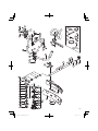
Installation of cutting attachment guard (Fig. 8)
NOTE
The guard bracket may come already mounted to the gear case
on some models.
CAUTION
Do not disassemble the recoil starter. You may get a possibility
of personal injury with recoil spring.
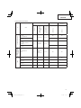
SPECIFICATIONS
Model CG25EUS CG25EUS (L)
Engine
Displacement (cm
3
)
Spark plug
Idling speed (min
-1
)
Speed of output shaft (min
-1
)
Max. engine output (kW)
25
NGK CMR5H
2800―3200
8900
0.81
25
NGK CMR5H
2800―3200
8900
0.81
Fuel tank capacity (cm
3
)550550
Engine oil capacity (cm
3
)80 80
Dry weight (kg) 5.4 5.2
Cutting attachment Type / Dia. (mm) Nylon cord Metal blade / 255 Nylon cord
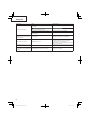
Sound pressure
level LpA
(dB (A))
(ISO22868)
Equivalent*
Uncertainty
88
3
88
3
88
3
Measured sound
power level LwA
(dB (A))
Guaranteed sound
power level LwA
(dB (A))
(2000/14/EC)
Racing
(2000/14/EC)
Racing
105
108
102
105
105
108
Vibration level (m/s
2
) (ISO
22867
)
Equivalent* (Front / Left handle)
Equivalent* (Rear / Right handle)
Uncertainty
4.6
4.6
1.5
6.5
5.0
1.5
4.8
3.2
1.5

10
English
Install the cutting attachment guard on drive shaft tube against
angle transmission. Tighten the guard bracket fi rmly so that the
cutting attachment guard does not swing or move down during
operation.
Install the cutting attachment guard to the guard bracket, which also
secures the guard to the gear case using the two guard mounting
screws.
WARNING
If an incorrect or faulty guard is fi tted, this may cause serious
personal injury.
CAUTION
Some cutting attachment guards are equipped with sharp line
limiters. Be careful with handling it.
When using a trimmer head with two piece type cutting attachment
guard, attach the guard extension to the cutting attachment guard.
(Fig. 9)
NOTE
○ When attaching the guard extension to the cutting attachment
guard, the sharp line limiter must be removed from the cutting
attachment guard (if so installed).
○ To remove the guard extension, refer to the drawings. Wear
gloves as the extension has a sharp line limiter, then push the
three square tabs on the guard one by one in order. (Fig. 10)
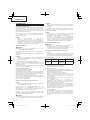
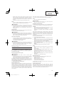
Installation of cutting attachment
WARNING
Install the cutting attachment properly and securely as
instructed in the handling instructions.
If not attached properly or securely, it may come off and cause
serious and/or fatal injury.
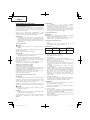
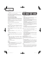
Installation of semi-auto cutting head
1. Function
Automatically feeds more nylon cutting line when it is tapped at
low rpm (not greater than 4500 min
-1
).
Specifi cations
Code
No.
Type of
attaching screw
Direction of
rotation
Size of
attaching screw
6696454 Female screw Counterclockwise M10×P1.25-LH
Applicable nylon cord
Cord diameter: Φ3.0 mm Length: 2 m
Cord diameter: Φ2.4 mm Length: 4 m
2. Precautions
○ The case must be securely attached to the cover.
○ Check the cover, case and other components for cracks or
other damage.
○ Check the case and button for wear.
If the wear limit mark (12) on the case is no longer visible or
there is a hole in the bottom (13) of the button, change the new
parts immediately. (Fig. 11)
○ The cutting head must be securely mounted to the unit’s gear
case.
○ For outstanding performance and reliability, always use Hitachi
nylon cutting line. Never use wire or other materials that could
become a dangerous projectile.
○ If the cutting head does not feed cutting line properly, check
that the nylon line and all components are properly installed.
Contact Hitachi Authorized Service Centers if you need
assistance.
3. Installation (Fig. 12)
○ Install cutting head on gear case of grass trimmers/brush
cutters. The mounting nut (14) is left-hand-threaded. Turn
clockwise to loosen/counterclockwise to tighten.
NOTE
○ Since the cutter holder cap is not used here, keep it for when a
metal blade is used, if so equipped.
Insert Allen wrench (15) into the hole of the gear case in order to
lock the cutter holder.
4. Adjusting line length
○ Set the engine speed as low as possible and tap the head on
the ground. The nylon line will be drawn out about 3 cm with
each tap. (Fig. 13)
Also, you can extend the nylon line by hand but the engine must
be completely stopped. (Fig. 14)
○ Adjust the nylon line to the proper length of 11–14 cm before
each operation.
Installation of cutting blade (Fig. 15)
(If so equipped)
When installing a cutting blade, make sure that there are no cracks
or any damage in it and that the cutting edges are facing the correct
direction.
NOTE
○ When installing cutter holder cap (16), be sure to set concave
side upward.
○ Insert the alien wrench (15) into the hole of the angle
transmission in order to lock the cutter holder (17). Please note
that the cutter fi xing bolt or nut (18) has left-handed threads,
(clockwise to loosen/ counter-clockwise to tighten). Tighten the
fi xing bolt or nut with the box wrench.
CAUTION
○ Before operation, make sure the blade has been properly
installed.
○ If your unit is equipped with protection cover under a cutting
blade, check it for wear or cracks before operation. If any damage
or wear is found, replace it, as it is an article of consumption.
○ You have to wear gloves when handling the cutting blade.
WARNING
For Hitachi heads or Hitachi alloy head, use only fl exible, non-
metallic line recommended by the manufacturer. Never use
wire or wire ropes. They can break off and become a dangerous
projectile.
OPERATING PROCEDURES
Engine oil
○ Always use the specifi ed engine oil (multigrade oil of
classifi cation SAE 10W-30). Insuffi cient engine oil or using
engine oil other than the specifi ed type may cause breakdown
of the unit.
Filling up with engine oil
○ Place the unit horizontally on a clean, fl at surface.
○ Remove the oil cap and check whether the engine oil comes up
to the mouth of the oil tank opening. (Fig. 16)
○ If the oil level is low or when using the unit for the fi rst time, fi ll
the tank with engine oil up to the mouth of the oil tank opening.
○ If the engine oil is conspicuously dirty or discolored, change the
oil.
○ Tighten the oil cap securely after fueling.
○ When using the unit for the fi rst time, change the engine oil after
running the engine for approximately 10 hours. Subsequently,
change the oil after every 50 hours of operation.
CAUTION
○ To avoid the risk of burn injuries, allow the engine to cool
thoroughly before changing the engine oil.

11
English
○ To prevent breakdown, ensure that no sand or dirt gets into the
tank while refueling.
Fuel
WARNING
○ Provide good ventilation, when fueling or handling fuel.
○ Fuel contains highly fl ammable and it is possible to get the
serious personal injury when inhaling or spilling on your body.
Always pay attention when handling fuel. Always have good
ventilation when handling fuel inside building.
○ Always use branded 89 octane unleaded gasoline.
○ Do not use a mixture of gasoline and engine oil as this may lead
to starter failure or power reduction.
Fueling
WARNING
○ Always shut off the engine before refueling.
○ Slowly open the fuel tank, when fi lling up with fuel, so that
possible over-pressure disappears.
○ Tighten the fuel cap carefully, after fueling.
○ Always move the trimmer at least 3 m from the fueling area
before starting.
○ Always wash any spilled fuel from clothing immediately with
soap.
○ Be sure to check for any fuel leakage after refueling.
Before fueling, clean the tank cap area carefully, to ensure that no
dirt falls into the tank.
Starting
CAUTION
Before starting, make sure the cutting attachment does not
touch anything.
1. Set ignition switch (19) to ON position. (Fig. 17)
* Push priming bulb (20) several times so that fuel fl ows through
the bulb or return pipe. (Fig. 18)
2. Set choke lever (21) to START position (closed) (A) (Fig. 19)
3. Pull recoil starter briskly, taking care to keep the handle in your
grasp and not allowing it to snap back.
4. When you hear the engine want to start, return choke lever to
RUN position (open) (B). Then pull recoil starter briskly again.
NOTE
If engine does not start, repeat procedures from 2 to 4.
5. After starting engine, then allow the engine about 2–3 minutes
to warm up before subjecting it to any load.
6. Check that the cutting attachment does not rotate when the
engine is idling.
Cutting (Fig. 20, 21, 22)
○ When cutting, operate engine at over 6500 min
-1
. Extended
time of use at low rpm may wear out the clutch prematurely.
○ Cut grass from right to left.
○ Blade thrust may occur when the spinning blade contacts a
solid object in the critical area.
A dangerous reaction may occur causing the entire unit and
operator to be thrust violently. This reaction is called blade
thrust. As a result, the operator may lose control of the unit
which may cause serious or fatal injury. Blade thrust is more
likely to occur in areas where it is diffi cult to see the material to
be cut.
○ Wear the harness as shown in the fi gure (if so equipped). The
blade turns counter-clockwise, therefore, be advised to operate
the unit from right to left for effi cient cutting. Keep onlookers out
of working area at least 15 m.
○ Use in accordance with local laws and regulations.
NOTE
Press the quick release button or pull emergency release fl ap
(If so equipped) in the event of emergency.
WARNING
If cutting attachment should strike against stones or other
debris, stop the engine and make sure that the attachment and
related parts are undamaged. When grass or vines wrap around
attachment, stop engine and attachment and remove them.
Stopping (Fig. 23)
Decrease engine speed and run at an idle for a few minutes, then
turn off ignition switch (19).
WARNING
A cutting attachment can injure while it continues to spin after
the engine is stopped or power control is released. When the
unit is turned off , make sure the cutting attachment has stopped
before the unit is set down.
Semi-auto cutting head
○ When cutting, operate engine at over 6500 min
-1
. Extended
time of use at low rpm may wear out the clutch prematurely.
○ Cut grass from right to left.
WARNING
A cutting attachment can injure while it continues to spin after
the engine is stopped or power control is released. When the
unit is turned off , make sure the cutting attachment has stopped
before the unit is set down.
Automatically feeds more nylon cutting line when it is tapped at low
rpm (not greater than 4500 min
-1
).
MAINTENANCE
MAINTENANCE, REPLACEMENT OR REPAIR OF THE EMISSION
CONTROL DEVICES AND SYSTEMS MAY BE PERFORMED
BY ANY NON-ROAD ENGINE REPAIR ESTABLISHMENT OR
INDIVIDUAL.
Carburetor adjustment (Fig. 24)
WARNING
○ The cutting attachment may be spinning during carburetor
adjustments.
○ Never start the engine without the complete fan case and tube
assembled! Otherwise the clutch can come loose and cause
personal injuries.
In the carburetor, fuel is mixed with air. When the engine is test
run at the factory, the carburetor is basically adjusted. A further
adjustment may be required, according to climate and altitude. The
carburetor has one adjustment possibility:
T = Idle speed adjustment screw.
Idle speed adjustment (T)
Check that the air fi lter is clean. When the idle speed is correct, the
cutting attachment will not rotate. If adjustment is required, close
(clockwise) the T-screw, with the engine running, until the cutting
attachment starts to rotate. Open (counter-clockwise) the screw
until the cutting attachment stops. You have reached the correct idle
speed when the engine runs smoothly in all positions well below the
rpm when the cutting attachment starts to rotate.
If the cutting attachment still rotates after idle speed adjustment,
contact Hitachi Authorized Service Centers.
NOTE
Standard Idle rpm is 2800–3200 min
-1
.
WARNING
When the engine is idling the cutting attachment must under no
circumstances rotate.
Changing the engine oil
Dirty engine oil will considerably reduce the service life of the
engine. Check and change the engine oil regularly.

12
English
CAUTION
○ To avoid the risk of burn injuries, allow the engine to cool
thoroughly before changing the engine oil.
○ To prevent breakdown, ensure that no sand or dirt gets into the
tank while refueling.
When to change the oil: When fi rst using the unit, after
approximately 10 hours of operation or after 1 month, whichever
occurs earlier; subsequently, after every 50 hours of operation or
every 6 months, whichever occurs earlier.
Specifi ed engine oil: Multigrade oil of classifi cation SAE 10W-30
Engine oil capacity: 80 ml
1. Turn off the ignition switch.
2. Check that the fuel cap is securely tightened.
3. Remove the oil cap, tilt the unit so that the oil tank opening is on
the underside and drain the engine oil into a container. (Fig. 25)
4. When all the engine oil has been drained, place the unit
horizontally on a clean, fl at surface.
5. Fill the oil tank with engine oil up to the mouth of the oil tank
opening. (Fig. 16)
6. Tighten the oil cap securely by hand.
NOTE
○ Do not dispose of waste engine oil with garbage or into the
ground.
Dispose of the oil according to the specifi ed method in your
area.
If you are unsure, contact the retailer where the oil was
purchased.
○ Fill the oil tank with the specifi ed amount of engine oil.
Too much or too little engine oil may result in engine
breakdown.
○ Engine oil deteriorates naturally even if unused.
Change the engine oil regularly.
Air fi lter (Fig. 26)
The air fi lter must be cleaned from dust and dirt in order to avoid:
○ Carburetor malfunctions
○ Starting problems
○ Engine power reduction
○ Unnecessary wear on the engine parts
○ Abnormal fuel consumption
Clean the air fi lter daily or more often if working in exceptionally
dusty areas.
Cleaning the air fi lter
Remove the air fi lter cover and the fi lter (22). Rinse it in warm soap
suds. Check that the fi lter is dry before reassembly. An air fi lter
that has been used for some time cannot be cleaned completely.
Therefore, it must regularly be replaced with a new one. A damaged
fi lter must always be replaced.
Fuel fi lter (Fig. 27)
Drain all fuel from fuel tank and pull fuel fi lter line from tank. Pull
fi lter element out of holder assembly and rinse element in warm
water with detergent.
Rinse thoroughly until all traces of detergent are eliminated.
Squeeze, do not wring, away excess water and allow element to air
dry.
NOTE
If element is hard due to excessive dirt buildup, replace it.
Spark plug (Fig. 28)
The spark plug condition is infl uenced by:
○ An incorrect carburetor setting
○ A dirty air fi lter
○ Hard running conditions (such as cold weather)
○ Too much engine oil
These factors cause deposits on the spark plug electrodes, which
may result in malfunction and starting diffi culties. If the engine
is low on power, diffi cult to start or runs poorly at idling speed,
always check the spark plug fi rst. If the spark plug is dirty, clean it
and check the electrode gap. Re-adjust if necessary. The correct
gap is 0.6 mm. The spark plug should be replaced after about 100
operation hours or earlier if the electrodes are badly eroded.
NOTE
In some areas, local law requires using a resistor spark plug
to suppress ignition signals. If this machine was originally
equipped with resistor spark plug, use same type of spark plug
for replacement.
Angle transmission (Fig. 29)
Check angle transmission or angle gear for grease level about
every 50 hours of operation by removing the grease fi ller plug on
the side of angle transmission.
If no grease can be seen on the fl anks of the gears, fi ll the
transmission with quality lithium based multipurpose grease up to
3/4. Do not completely fi ll the transmission.
Semi-auto cutting head
Nylon line replacement
(1) Remove the case (23) by fi rmly pushing inward the locking tabs
with your thumbs as shown in Fig. 30.
(2) After removing the case, take out the reel and discard the
remaining line.
(3) Fold the new nylon line unevenly in half as shown in picture.
Hook the U-shaped end of the nylon line into the groove (24) on
the center partition of the reel.
Wind both halves of the line on the reel in the same direction,
keeping each half of the line on its own side of the partition.
(Fig. 31)
(4) Push each line into the stopper holes (25), leaving the loose
ends approx. 10 cm in length. (Fig. 32)
(5) Insert both loose ends of the line through the cord guide (26)
when placing the reel in the case. (Fig. 33)
NOTE
When placing a reel in the case, try to line up the stopper holes
(25) with the cord guide (26) for easier line release later.
(6) Place the cover over the case so that the cap locking tabs on
the case meet the long holes on the cover. Then push the case
securely until it clicks into place. (Fig. 34)
(7) The initial cutting line length should be approx. 11–14 cm and
should be equal on both sides. (Fig. 35)
Blade (Fig. 36)
WARNING
Wear protective gloves when handling or performing
maintenance on the blade.
○ Use a sharp blade. A dull blade is more likely to snag and thrust.
Replace the fastening nut if it is damaged and hard to tighten.
○ When replacing blade, purchase one recommended by Hitachi,
with a 25.4 mm (one inch) fi tting hole.
○ In the case of a 3 tooth blade (27), it can be used on either side.
○ Use the correct blade for the type of work.
○ When replacing blades, use appropriate tools.
○ When cutting edges become dull, re-sharpen or fi le as shown
in the illustration. Incorrect sharpening may cause excessive
vibration.
○ Discard blades that are bent, warped, cracked, broken or
damaged in any way.
NOTE
When sharpening blade it is important to maintain an original
shape of radius at the base of the tooth to avoid cracking.
Maintenance schedule
Below you will fi nd some general maintenance instructions. For
further information please contact Hitachi Authorized Service
Centers.

13
English
Daily maintenance
○ Clean the exterior of the unit.
○ Check that the harness is undamaged.
○ Check the cutting attachment guard for damage or cracks.
Change the guard in case of impacts or cracks.
○ Check that the cutting attachment is properly centred, sharp,
and without cracks. An off -centre cutting attachment induces
heavy vibrations that may damage the unit.
○ Check that the cutting attachment nut is suffi ciently tightened.
○ Make sure that the blade transport guard is undamaged and
that it can be securely fi tted.
○ Check that nuts and screws are suffi ciently tightened.
○ Check the volume and condition of the engine oil.
○ Check that the unit is undamaged and free of defects.
Weekly maintenance
○ Check the starter, especially the cord and return spring.
○ Clean the exterior of the spark plug.
○ Remove it and check the electrode gap. Adjust it to 0.6 mm, or
change the spark plug.
○ Check that the angle gear is fi lled with grease up to 3/4.
○ Clean the air fi lter.
Monthly maintenance
○ Rinse the fuel tank with gasoline.
○ Clean the exterior of the carburetor and the space around it.
○ Clean the fan and the space around it.
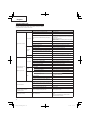
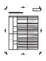
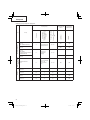
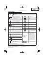
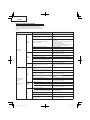
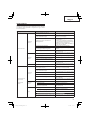
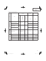
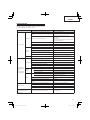
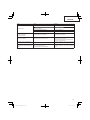
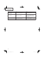
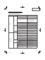
List of recommended accessories
Type Name
Specifi cation LOOP HANDLE BIKE HANDLE
Diameter
Feed System Adapter
or
No. of Teeth (Blade)
Blade Thickness (mm)
or
Trimmer line Diameter
(mm)
CG25EUS (L)
CG25EUS
ALUMINUM HEADS
NYLON HEAD
CH-100
(W/NYLON LINE)
4” Pre-Cut Line 2.2 – 3.0
●●
NYLON HEAD
CH-100
●●
NYLON HEAD
CH-300
(W/CUTTER HOLDER
CAP)
5” Manual line feed 2.2 – 2.7
NYLON HEAD
CH-300
TAP & GO NYLON
HEADS
NYLON HEAD
BF-5
5”
L M10 x 1.25 Nut
L M8 x 1.25
2.2 – 3.0 ●●
BLADES
BLADE
B3/10/2.0
10” 3 2.0 ●
BLADE
B3/12/3.0
12” 3 3.0
BLADE
B4/9/1.6
9” 4 1.6 ●
BLADE
B4/10/1.6
10” 4 1.6 ●

14
English
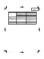
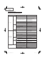
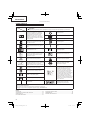
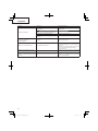
TROUBLESHOOTING
Use the inspections in the table below if the tool does not operate
normally. If this does not remedy the problem, consult your dealer
or the Hitachi Authorized Service Center.
Condition Cause Remedy
Engine does not start
Fuel system
Fuel tank is empty or fuel level is low Fill the fuel tank
Fuel tank contains old fuel (offensive odor) Replace with new fuel
Too much fuel is absorbed and spark plug is
wet
1. Disconnect the spark plug and allow to dry
2. Pull the starter handle 5 or 6 times to remove the
surplus fuel
3. Attach the spark plug
4. Set the choke lever to RUN position and pull the
starter handle
Fuel fi lter is clogged with dirt Clean the fuel fi lter
Fuel pipe is bent or disconnected Ensure that the fuel fl ows smoothly
Carburetor malfunction Contact Hitachi Authorized Service Centers
Electrical
system
Stop switch lead has short-circuited Contact Hitachi Authorized Service Centers
Spark plug is dirty Replace or clean the spark plug
Electrode gap is too big Adjust the gap to 0.6mm
Poor connection between high tension cable
and spark plug
Reconnect
Electrical system malfunction Contact Hitachi Authorized Service Centers
Other Muffl er exhaust port is clogged with carbon
Contact Hitachi Authorized Service Centers for
repair
Engine starts but cuts
out straightaway
Engine is apt to cut
out
Fuel system
Fuel tank is empty or fuel level is low
Fill the fuel tank
Fuel tank contains old fuel (offensive odor) Replace with new fuel
Engine oil has not been added
Contact Hitachi Authorized Service Centers
Choke lever is in START position Set the choke lever to RUN position
Air has got into fuel system Reconnect the fuel pipe or joint
Carburetor malfunction Contact Hitachi Authorized Service Centers
Electrical
system
Ignition failure
Spark plug failure Replace with new spark plug
Electrical system failure Contact Hitachi Authorized Service Centers
Other
Engine overheating
Wrong spark plug model
Replace with designated part
See “SPECIFICATIONS”
Dirty air cleaner Clean
Carbon clogging (muffl er exhaust port) Clean
Insuffi cient compression (piston, piston ring,
cylinder)
Contact Hitachi Authorized Service Centers
Abnormal vibration
Cutting attachment is not properly installed See “Installation of cutting attachment”
Handle, handle bracket or other fastening part
is loose
Check and tighten
Blade is bent or damaged Replace with new blade
Grass is wrapped round gear case Remove grass
Engine is running but cutting
attachment does not move
Movement is poor
Grass is wrapped round gear case Remove grass and dirt
Engine does not stop Stop switch failure
Set the choke lever to START position to stop the
engine
Cease use immediately and contact Hitachi
Authorized Service Centers

15
English
Condition Cause Remedy
Engine stops when throttle is closed Idle speed is too low Contact Hitachi Authorized Service Centers
Cutting attachment continues rotating
when throttle is closed
Idle speed is too high
Throttle wire is too taut
Contact Hitachi Authorized Service Centers

(Übersetzung der ursprünglichen Anleitung)
Deutsch
16
SYMBOLBEDEUTUNGEN
HINWEIS: Nicht alle Geräte sind mit diesen Symbolen versehen.
Symbole
WARNUNG
Die folgenden Symbole werden für diese Maschine verwendet. Achten Sie darauf, diese vor der Verwendung
zu verstehen.
Es ist wichtig, dass Sie sich mit den
nachfolgenden Vorsichtsmaßnahmen
und Warnungen vertraut machen und
diese befolgen. Unvorsichtige oder
unsachgemäße Handhabung des Geräts
kann schwere oder tödliche Verletzungen
zur Folge haben.
Notfallstopp
Motorölfüllung
Kraftstoff füllung
Lesen, verstehen und befolgen Sie alle
Warnungen und Anweisungen in dieser
Anleitung und am Gerät selbst.
Leerlaufdrehzahleinstellung
Bei Gebrauch des Geräts immer Gesichts-,
Kopf- und Gehörschutz tragen.
Ansaugpumpe
Wenn dieses Zeichen am Gerät angebracht
ist, keine starren Messer/Metallmesser
verwenden.
4
Garantierter Schallleistungspegel
Kinder und Zuschauer in einem Abstand
von 15 m vom Gerät halten. Falls sich
jemand nähert, den Motor und das Zubehör
sofort ausschalten.
Heiße Oberfl äche – Eine Berührung
der heißen Oberfl äche kann schwere
Verbrennungen verursachen.
Auf hochgeschleuderte Gegenstände
achten.
Das Heckenscheren-Anbauwerkzeug
kann nicht an Modellen mit diesem
Schild verwendet werden.
min
-1
Zeigt die maximale Drehzahl der Welle
an. Verwenden Sie kein Schneidzubehör,
dessen Maximaldrehzahl unter diesem
Wert liegt.
Ein Messerstoß ist möglich, wenn das
rotierende Messer im kritischen Bereich mit
einem massiven Gegenstand in Berührung
kommt. In diesem Fall kann es zu einer
gefährlichen Reaktion kommen, bei der
das gesamte Gerät und der Bediener
einem heftigen Stoß ausgesetzt werden.
Diese Reaktion wird als Messerstoß
bezeichnet. Das Resultat ist u.U., dass
der Bediener die Kontrolle über das Gerät
verliert und schwere oder lebensgefährliche
Verletzungen davonträgt. Messerstöße
sind in Arbeitsbereichen, wo das zu
schneidende Vegetationsmaterial nur
schwer einsehbar ist, wahrscheinlicher.
Handschuhe sind dann zu tragen, wenn
dies notwendig ist, z.B. bei der Montage
der Schneidausrüstung.
Rutschfestes Schuhwerk tragen, das guten
Halt bietet.
Choke – Betriebsposition (off en)
Choke – Startposition (geschlossen)
Ein/Start
Bezeichnet den Griff stangenplatz.
Griff stange nicht oberhalb dieses
Punktes anbringen.
Aus/Stopp
Vor dem Gebrauch Ihres Geräts
• Bedienungsanleitung sorgfältig durchlesen.
• Montage und Einstellung der Schneidausrüstung kontrollieren.
• Gerät starten und Vergasereinstellung prüfen. Siehe “WARTUNG”.
Inhalt
TEILEBEZEICHNUNG EN ................................................................17
WARN- UND SICHERHEITSHINWEISE .........................................18
TECHNISCHE DATEN .....................................................................19
ZUSAMMENBAU .............................................................................20
BE TRIEB .......................................................................................... 21
WARTU NG .......................................................................................2 2
FEHLERSUCHE UND -BESEITIGUNG ..........................................25

14
6
7
5
4
2
13
9
11
9
11
13
8
2
7
6
14
5
4
3
12
1
17
18
19
20
21
22
23
16
10
15
TEILEBEZEICHNUNGEN
Da dieses Handbuch für mehrere Modelle gilt, können die
Abbildungen gegebenenfalls von Ihrem Gerät abweichen.
Verwenden Sie die für Ihr Gerät geltenden Anweisungen.
1. Benzintank
2. Gashebel
3. Startgriff
4. Schutz Schneide-Zubehör
5. Schneid-Vorsatzgerät
6. Antriebswellenrohr
7. G riff
8. Tragegurtöse
9. Zündschalter
10. Tragegurt
11. Gashebelsperre
12. Chokehebel
13. Motor
14. Winkelgetriebe
15. Kombischlüssel
16. Bedienungsanleitung
17. Öleinfülldeckel
18. Sechskantschlüssel
19. Spanner
20. Brille
21. Klingenabdeckung (je nach Ausstattung)
22. Schwenkkappe
23. Kabelbinder (je nach Ausstattung)
Deutsch
17
CG25EUS (L)
CG25EUS

WARN- UND SICHERHEITSHINWEISE
Bedienersicherheit
○ Immer einen Gesichtsschutz bzw. eine Schutzbrille tragen.
○ Tragen Sie immer eine lange, schwere Hose, rutschfeste
Schuhe, Handschuhe und ein langärmliges Hemd. Das
Arbeiten mit lockerer Kleidung, Schmuck, kurzen Hosen,
Sandalen oder barfuß ist zu vermeiden. Das Haar ist so zu
sichern, dass es nicht bis zu den Schultern herunterhängt.
○ Das Gerät darf nicht von Personen bedient werden, die
übermüdet oder krank sind oder unter Alkohol- oder
Medikamenteneinfl uss stehen.
○ Das Gerät nicht bei Nacht oder schlechten
Witterungsverhältnissen mit eingeschränkter Sicht bedienen.
Das Gerät zudem nicht bei Regen oder kurz nach einem
Regenschauer betätigen.
Arbeit auf rutschigem Untergrund kann zu Unfällen führen,
wenn Sie das Gleichgewicht verlieren.
○ Unter keinen Umständen zulassen, dass ein Kind oder eine
unerfahrene Person mit dem Gerät arbeitet.
○ Langfristige Aussetzung zu lauten Geräuschen kann
zu bleibenden Hörschäden führen. Tragen Sie einen
zugelassenen Gehörschutz. Die Umgebung im Auge behalten.
Auf Beistehende achten, die unter Umständen ein Problem
signalisieren. Die Schutzbekleidung erst nach Abstellen des
Motors wieder ablegen.
○ Kopfschutz tragen.
○ Der Motor darf nie innerhalb geschlossener Räume oder
Gebäude gestartet bzw. betrieben werden. Einatmen der
Abgase kann den Tod zur Folge haben.
○ Die Griff e frei von Öl und Kraftstoff halten.
○ Hände von den Schneiden fernhalten.
○ Das Gerät nicht an der Schneidgarnitur fassen bzw. halten.
○ Beim Montieren oder Entfernen des Schneidwerkzeugs
müssen Handschuhe getragen werden.
Nichtbeachtung kann eine Verletzung zur Folge haben.
○ Das Gerät nach dem Ausschalten des Motors erst am
Boden abstellen, wenn das Schneidwerkzeug zum Stillstand
gekommen ist.
○ Bei Dauereinsatz von Zeit zu Zeit eine Pause einlegen als
vorbeugende Maßnahme gegen die Weißfi ngerkrankheit, die
durch ständige Vibration verursacht wird.
WARNUNG
○ Vibrationsdämpfungssysteme sind kein garantierter Schutz
gegen die Weißfi ngerkrankheit bzw. das Karpaltunnelsyndrom.
Daher ist bei regelmäßigem Dauereinsatz des Geräts der
Zustand von Fingern und Handwurzel aufmerksam zu
beobachten. Falls Symptome der obengenannten Krankheiten
auftreten, sofort einen Arzt aufsuchen.
○ Träger eines medizinischen elektrischen bzw. elektronischen
Geräts (Herzschrittmacher u. dgl.) sollten sich vor dem
Gebrauch eines Motorgeräts von Ihrem Arzt sowie dem
Hersteller des Geräts diesbezüglich beraten lassen.
Geräte-/Maschinensicherheit
○ Das Gerät vor jedem Einsatz einer eingehenden Kontrolle
unterziehen. Beschädigte Teile ersetzen. Das Gerät auf
auslaufenden Kraftstoff untersuchen und sicherstellen, dass
alle Befestigungsteile vorhanden und sicher angezogen sind.
○ Gerissene, ausgebrochene oder auf andere Weise
beschädigte Teile sind vor dem Einsatz des Gerätes durch
neue zu ersetzen. Defekte Teile vergrößern das Unfallrisiko
und können eine Verletzung zur Folge haben.
○ Es ist darauf zu achten, dass die Schutzvorrichtung
ordnungsgemäß angebracht ist.
○ Während der Vergasereinstellung dürfen sich andere Personen
nicht in der Nähe aufhalten.
○ Nur das vom Hersteller für dieses Gerät empfohlene Zubehör
darf verwendet werden.
WARNUNG
○ Keinesfalls das Gerät in irgendeiner Weise abändern. Das
Gerät nur für die Zwecke verwenden, für die es bestimmt ist.
○ Nicht autorisierte Änderungen und/oder Zubehörteile können
eine schwere Körperverletzung oder den Tod des Bedieners
oder Anderer zur Folge haben.
Kraftstoff sicherheit
○ Kraftstoff im Freien und von Funken und Feuer entfernt
mischen und einfüllen.
○ Einen für Kraftstoff e zugelassenen Behälter verwenden.
○ In der Nähe des Kraftstoff s, des Geräts sowie beim Arbeiten mit
dem Gerät ist das Rauchen zu unterlassen.
○ Vor dem Starten des Motors muss eventuell verschütteter
Kraftstoff restlos entfernt werden.
○ Zum Starten des Motors das Gerät mindestens 3 m von der
Kraftstoff einfüllstelle entfernen.
○ Vor dem Abnehmen des Tankdeckels den Motor ausschalten.
○ Vor der Einlagerung des Geräts den Kraftstoff tank leeren. Es
wird empfohlen, den Kraftstoff nach jedem Einsatz abzulassen.
Mit gefülltem Tank ist das Gerät so zu lagern, dass kein
Kraftstoff ausläuft.
○ Gerät und Kraftstoff an einem Ort lagern, wo Kraftstoff dämpfe
nicht mit Funken oder off enen Flammen von Wassererhitzern,
Elektromotoren oder elektrischen Schaltern, Öfen usw. in
Berührung kommen können.
WARNUNG
Kraftstoff ist leicht entfl ammbar, kann explodieren und schadet
den Atemwegen, weshalb bei der Handhabung von und der
Befüllung mit Kraftstoff entsprechend umsichtig vorzugehen
ist.
Schneidsicherheit
○ Das Gerät nur zum Mähen von Gras und zum Schneiden von
Buschwerk und Unterholz einsetzen.
○ Vor jedem Gebrauch die zu mähende Fläche inspizieren.
Gegenstände entfernen, die hochgeschleudert werden oder
sich im Mähkopf verfangen könnten.
○ Zum Schutz der Atmungsorgane beim Mähen von Gras,
auf dem Insektenvernichtungsmittel versprüht wurde, eine
Aerosolschutzmaske tragen.
○ Kinder, Tiere, Umstehende, Helfer usw. dürfen sich nicht
innerhalb der 15 m-Gefahrenzone aufhalten. Den Motor sofort
abstellen, wenn sich jemand nähert.
○ Der Motor muss sich immer auf der rechten Körperseite
befi nden.
○ Gerät fest mit beiden Händen halten.
○ Auf sicheren Stand und gutes Gleichgewicht achten. Nicht zu
weit vorbeugen.
Wenn man beim Arbeiten das Gleichgewicht verliert, kann dies
eine Verletzung zur Folge haben.
○ Schneidwerkzeug und Schalldämpfer bei laufendem Motor
vom Körper fernhalten.
○ Die Schneidgarnitur stets unter Kniehöhe halten.
○ Bei Standortwechseln unbedingt den Motor ausschalten und
sicherstellen, dass das Schneidwerkzeug still steht.
○ Das Gerät niemals mit laufendem Motor auf dem Boden
abstellen.
○ Vor dem Entfernen von Schmutz oder Gras vom
Schneidwerkzeug den Motor ausschalten und sicherstellen,
dass die Kette zum Stillstand gekommen ist.
○ Beim Arbeiten mit Motorgeräten stets einen Verbandskasten
mitführen.
○ Der Motor darf nie innerhalb geschlossener Räume oder
Gebäude und/oder in der Nähe entfl ammbarer Flüssigkeiten
gestartet bzw. betrieben werden. Einatmen der Abgase kann
den Tod zur Folge haben.
○ Bei schwacher Geräteleistung oder seltsamen Geräuschen
oder Vibrationen des Geräts den Motor sofort abstellen und
das Gerät durch Ihren Fachhändler inspizieren und reparieren
lassen.
Eine weitere Verwendung in diesem Zustand kann zu
Verletzungen oder der Beschädigung des Geräts führen.
○ Beim Gebrauch die örtlich gültigen Gesetze und Vorschriften
einhalten.
Wartungssicherheit
○ Das Gerät vorschriftsmäßig warten.
Deutsch
18

○ Vor Durchführung von Wartungsarbeiten die Zündkerze
entfernen, sofern es sich nicht um eine Vergasereinstellung
handelt.
○ Während der Vergasereinstellung dürfen sich andere Personen
nicht in der Nähe aufhalten.
○ Nur Original-Ersatzteile von Hitachi verwenden, wie vom
Hersteller empfohlen.
Transport und Lagerung
○ Das Gerät mit ausgeschaltetem Motor tragen und den
Schalldämpfer vom Körper fernhalten.
○ Den Motor abkühlen lassen, den Kraftstoff tank entleeren und
das Gerät sichern, bevor es gelagert oder transportiert wird.
○ Vor der Einlagerung des Geräts den Kraftstoff tank leeren. Es
wird empfohlen, den Kraftstoff nach jedem Einsatz abzulassen.
Mit gefülltem Tank ist das Gerät so zu lagern, dass kein
Kraftstoff ausläuft.
○ Das Gerät so lagern, dass es nicht in Kinderhände gerät.
○ Das Gerät sorgfältig reinigen und warten, um es dann an einem
trockenen Ort zu lagern.
○ Bei Transport oder Lagerung darauf achten, dass der
Zündschalter ausgeschaltet ist.
○ Bei Transport und Lagerung den Klingenschutz auf die Klinge
aufsetzen.
○ Sie müssen die Maschine beim Transport sichern, um
Auslaufen von Kraftstoff , Schäden, oder Verletzungen zu
verhindern.
In Situationen, die nicht in dieser Anleitung behandelt sind,
entsprechende Vor- und Umsicht walten lassen. Sollten Sie
Hilfe benötigen, wenden Sie sich an einem einer von Hitachi
autorisierten Service-Werkstatt. Die folgenden Wörter sind
Abschnitten vorangestellt, denen besondere Aufmerksamkeit
gewidmet werden sollte:
WARNUNG
Kennzeichnet Anweisungen, deren Nichtbefolgung eine
schwere Verletzung oder den Tod zur Folge haben kann.
VORSICHT
Kennzeichnet Anweisungen, deren Nichtbefolgung eine
Verletzung oder Sachschaden zur Folge haben kann.
HINWEIS
Kennzeichnet nützliche Informationen für den
vorschriftsmäßigen Gebrauch.
VORSICHT
Den Zugstarter nicht zerlegen. Die Feder der Vorrichtung kann
Verletzungen verursachen.
Deutsch
19
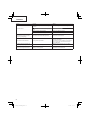
TECHNISCHE DATEN
Modell CG25EUS CG25EUS (L)
Motor
Hubvolumen (cm
3
)
Zündkerze
Leerlaufdrehzahl (min
-1
)
Drehzahl der Ausgangswelle (min
-1
)
Max. Motorleistung (kW)
25
NGK CMR5H
2800―3200
8900
0,81
25
NGK CMR5H
2800―3200
8900
0,81
Kraftstoff tankvolumen (cm
3
)550 550
Motorölfassungsvermögen (cm
3
)
80 80
Trockengewicht (kg) 5,4 5,2
Schneid-
Vorsatzgerät
Typ / Durchm.
(mm)
Nylonschnur Metallklinge / 255 Nylonschnur
Schalldruckpegel
LpA (dB (A))
(ISO22868)
Äquivalen*
Unsicherheit
88
3
88
3
88
3
Gemessener
Schallpegel
LwA (dB (A))
Garantierter
Schallpegel
LwA (dB (A))
(2000/14/EG)
Volllast
(2000/14/EG)
Volllast
105
108
102
105
105
108
Vibrationspegel (m/s
2
) (ISO22867)
Äquivalent* (Vorderer / linker Griff )
Äquivalent* (Hinterer / rechter Griff )
Unsicherheit
4,6
4,6
1,5
6,5
5,0
1,5
4,8
3,2
1,5
HINWEIS
Die entsprechenden Geräusch-/Vibrationspegel werden als zeitgewichtete Energiesumme für Geräusch-/Vibrationspegel unter
verschiedenen Arbeitsbedingungen mit folgender Zeitaufteilung berechnet:
* : 1/2 Leerlauf, 1/2 schnell
Änderung der technischen Daten jederzeit vorbehalten.

Deutsch
20
ZUSAMMENBAU
Antriebswelle und Motor (Abb. 1)
Den Rohrblockierungsbolzen (1) lockern, so dass die Bolzenspitze
das Antriebswellenrohr beim Einschieben nicht behindert.
Halten Sie beim Einschieben des Antriebswellenrohrs den
Rohrblockierungsbolzen so fest, dass Blockierungen durch das
inneren Zubehör vermieden werden.
Die Antriebswelle soweit in das Kupplungsgehäuse einschieben,
bis zur Markierung (2) auf dem Antriebswellenrohr am
Kupplungsgehäuse liegt.
HINWEIS
Wenn sich die Antriebswelle nur schwer bis zur
Markierung einschieben lässt, die Antriebswelle am
Schneidvorrichtungsende fassen und beim Einschieben im
oder gegen den Uhrzeigersinn drehen. Den Blockierungsbolzen
so anziehen, dass er in das Loch des Antriebswellenrohrs
eingreift. Dann die Spannschraube fest anziehen (3).
Montage des Handgriff s
WARNUNG
Verwenden Sie stets einen Messerschutz (4) und einen
Tragegurt mit dem Bügelgriff . (Abb. 2)
Den Handgriff zum Motor geneigt an das Antriebswellenrohr
anbringen.
Den Handgriff vor der Inbetriebnahme auf eine komfortable Position
einstellen.
HINWEIS
Falls auf dem Antriebswellenrohr Ihres Geräts ein Schild mit
Informationen zur Handgriff position angebracht ist, halten Sie
sich an die Darstellung.
Den Griff halter (5) von der Einheit entfernen. (Abb. 3)
Den Griff einsetzen und den Griff halter mit vier Schrauben locker
befestigen. Den Winkel je nach Bedarf ausrichten. Dann die
Schrauben festziehen.
Das Schutzrohr mit Hilfe von Kabelklemmen (6) an der Antriebswelle
oder dem Griff befestigen. (Abb. 4)
Gaszug / Stoppkabel (Abb. 6)
Den Luftfi lterdeckel abnehmen. (Abb. 5)
Die Stoppkabel anschließen. (Abb. 7)
Falls das äußeren Ende des Gaszugs (7) an Ihrem Gerät über ein
Gewinde verfügt, schrauben Sie es ganz in die Einstellstrebe (8)
ein und befestigen Sie danach dieses Kabelende mit Hilfe der
Einstellmutter (9) an der Kabeleinstellstrebe (8).
Verbinden Sie das Ende des Gaszugs (10) mit dem Vergaser (11)
und schrauben Sie die im Werkzeugbeutel mitgelieferte Drehkappe
(falls vorhanden) auf den Drehring.
Bringen Sie den Luftfi lterdeckel an.
Installation des Schneid-Vorsatzschutzes (Abb. 8)
HINWEIS
Bei einigen Modellen wird das Getriebegehäuse bereits mit
montierten Schutzhalter geliefert.
Installieren Sie den Schneid-Vorsatzschutz auf dem
Antriebswellenrohr am Winkelgetriebe. Ziehen Sie den
Schutzbügel fest an, sodass der Schneid-Vorsatzschutz beim
Betrieb nicht schwingen bzw. sich bewegen kann.
Installieren Sie den Schneid-Vorsatzschutz mit den beiden
Schrauben für die Montage des Schutzes am Schutzbügel, der den
Schutz auch am Getriebegehäuse festhält.
WARNUNG
Wenn eine falsche oder defekte Schutzvorrichtung angebracht
wird, kann dies eine schwere Körperverletzung verursachen.
VORSICHT
Manche Schneid-Vorsatzschutzvorrichtungen haben scharfe
Kantenbegrenzer. Seien Sie daher bei der Handhabung
vorsichtig.
Bei Verwendung eines Trimmerkopfs mit zweiteiligem Schneid-
Vorsatzschutz bringen Sie die Schutzverlängerung am Schneid-
Vorsatzschutz an. (
Abb. 9
)
HINWEIS
○ Beim Anbringen der Schutzverlängerung am Schneid-
Vorsatzschutz muss der scharfe Kantenbegrenzer (falls
installiert) vom Schneid-Vorsatzschutz entfernt werden.
○ Informationen zum Entfernen der Schutzverlängerung
entnehmen Sie den Abbildungen. Tragen Sie Handschuhe,
denn die Verlängerung hat eine scharfe Randbegrenzung,
schieben Sie dann die drei quadratischen Laschen auf der
Schutzabdeckung einzeln nacheinander zurecht. (Abb. 10)
Montage des Schneidwerkzeugs
WARNUNG
Montieren Sie das Schneidwerkzeug vorschriftsmäßig und
fest, wie in der Bedienungsanleitung vorgeschrieben.
Bei falschem oder lockerem Anbau kann es sich lösen und eine
schwere und/oder tödliche Verletzung verursachen.
Anbringung des halbautomatischen Schneidkopfs
1. Funktion
Durch Tippen des Schneidkopfs auf den Boden bei geringer
Drehzahl (weniger als 4500 Umdrehungen pro Minute) wird der
zur Verfügung stehende Nylonfaden automatisch verlängert.
Technische Daten
Artikelnr.
Befestigungs-
schraubentyp
Drehrichtung
Befestigungs-
schraubengröße
6696454 Hohlschraube
Gegen den
Uhrzeigersinn
M10×P1,25-LH
Verwendbarer Nylonfaden
Fadendurchmesser Φ3,0 mm Länge: 2 m
Fadendurchmesser Φ2,4 mm Länge: 4 m
2. Vorsichtsmaßnahmen
○ Das Gehäuse muss fest an der Abdeckung angebracht sein.
○ Abdeckung, Gehäuse und andere Komponenten auf Risse oder
andere Beschädigungen überprüfen.
○ Gehäuse und Knopf auf Verschleiß überprüfen.
Wenn die Verschleißgrenzwertmarkierung (12) auf dem
Gehäuse nicht mehr sichtbar ist, oder an der Unterseite des
Knopfs (13) ein Loch ist, tauschen Sie sie sofort gegen neue
Teile aus. (Abb. 11)
○ Der Schneidkopf muss fest auf dem Getriebegehäuse des
Geräts angebracht sein.
○ Um erstklassige Leistung und Zurverlässigkeit zu
gewährleisten, stets Nylonfäden von Hitachi verwenden.
Niemals Draht oder andere Materialien verwenden, die zu
gefährlichen Geschossen werden können.
○ Wenn die Schneidfadenbereitstellung durch den Schneidkopf
nicht ordnungsgemäß funktioniert, die korrekte Anbringung
des Nylonfadens und aller Komponenten kontrollieren. Sollten
Sie Hilfe benötigen, wenden Sie sich an einem einer von
Hitachi autorisierten Service-Werkstatt.
3. Anbringung (Abb. 12)
○ Den Schneidekopf am Getriebegehäuse des Rasentrimmers/
der Motorsense installieren. Die Befestigungsschraube
(14) ist mit einem Linksgewinde versehen. Durch Drehen im
Uhrzeigersinn lösen/durch Drehen gehen den Uhrzeigersinn
anziehen.
Strona się ładuje...
Strona się ładuje...
Strona się ładuje...
Strona się ładuje...
Strona się ładuje...
Strona się ładuje...
Strona się ładuje...
Strona się ładuje...
Strona się ładuje...
Strona się ładuje...
Strona się ładuje...
Strona się ładuje...
Strona się ładuje...
Strona się ładuje...
Strona się ładuje...
Strona się ładuje...
Strona się ładuje...
Strona się ładuje...
Strona się ładuje...
Strona się ładuje...
Strona się ładuje...
Strona się ładuje...
Strona się ładuje...
Strona się ładuje...
Strona się ładuje...
Strona się ładuje...
Strona się ładuje...
Strona się ładuje...
Strona się ładuje...
Strona się ładuje...
Strona się ładuje...
Strona się ładuje...
Strona się ładuje...
Strona się ładuje...
Strona się ładuje...
Strona się ładuje...
Strona się ładuje...
Strona się ładuje...
Strona się ładuje...
Strona się ładuje...
Strona się ładuje...
Strona się ładuje...
Strona się ładuje...
Strona się ładuje...
Strona się ładuje...
Strona się ładuje...
Strona się ładuje...
Strona się ładuje...
Strona się ładuje...
Strona się ładuje...
Strona się ładuje...
Strona się ładuje...
Strona się ładuje...
Strona się ładuje...
Strona się ładuje...
Strona się ładuje...
Strona się ładuje...
Strona się ładuje...
Strona się ładuje...
Strona się ładuje...
Strona się ładuje...
Strona się ładuje...
Strona się ładuje...
Strona się ładuje...
Strona się ładuje...
Strona się ładuje...
Strona się ładuje...
Strona się ładuje...
Strona się ładuje...
Strona się ładuje...
Strona się ładuje...
Strona się ładuje...
Strona się ładuje...
Strona się ładuje...
Strona się ładuje...
Strona się ładuje...
Strona się ładuje...
Strona się ładuje...
Strona się ładuje...
Strona się ładuje...
Strona się ładuje...
Strona się ładuje...
Strona się ładuje...
Strona się ładuje...
Strona się ładuje...
Strona się ładuje...
Strona się ładuje...
Strona się ładuje...
Strona się ładuje...
Strona się ładuje...
Strona się ładuje...
Strona się ładuje...
Strona się ładuje...
Strona się ładuje...
Strona się ładuje...
Strona się ładuje...
Strona się ładuje...
Strona się ładuje...
Strona się ładuje...
Strona się ładuje...
-
 1
1
-
 2
2
-
 3
3
-
 4
4
-
 5
5
-
 6
6
-
 7
7
-
 8
8
-
 9
9
-
 10
10
-
 11
11
-
 12
12
-
 13
13
-
 14
14
-
 15
15
-
 16
16
-
 17
17
-
 18
18
-
 19
19
-
 20
20
-
 21
21
-
 22
22
-
 23
23
-
 24
24
-
 25
25
-
 26
26
-
 27
27
-
 28
28
-
 29
29
-
 30
30
-
 31
31
-
 32
32
-
 33
33
-
 34
34
-
 35
35
-
 36
36
-
 37
37
-
 38
38
-
 39
39
-
 40
40
-
 41
41
-
 42
42
-
 43
43
-
 44
44
-
 45
45
-
 46
46
-
 47
47
-
 48
48
-
 49
49
-
 50
50
-
 51
51
-
 52
52
-
 53
53
-
 54
54
-
 55
55
-
 56
56
-
 57
57
-
 58
58
-
 59
59
-
 60
60
-
 61
61
-
 62
62
-
 63
63
-
 64
64
-
 65
65
-
 66
66
-
 67
67
-
 68
68
-
 69
69
-
 70
70
-
 71
71
-
 72
72
-
 73
73
-
 74
74
-
 75
75
-
 76
76
-
 77
77
-
 78
78
-
 79
79
-
 80
80
-
 81
81
-
 82
82
-
 83
83
-
 84
84
-
 85
85
-
 86
86
-
 87
87
-
 88
88
-
 89
89
-
 90
90
-
 91
91
-
 92
92
-
 93
93
-
 94
94
-
 95
95
-
 96
96
-
 97
97
-
 98
98
-
 99
99
-
 100
100
-
 101
101
-
 102
102
-
 103
103
-
 104
104
-
 105
105
-
 106
106
-
 107
107
-
 108
108
-
 109
109
-
 110
110
-
 111
111
-
 112
112
-
 113
113
-
 114
114
-
 115
115
-
 116
116
-
 117
117
-
 118
118
-
 119
119
-
 120
120


Hitachi CG25EUS Instrukcja obsługi
- Typ
- Instrukcja obsługi
- Niniejsza instrukcja jest również odpowiednia dla
w innych językach
- slovenčina: Hitachi CG25EUS Používateľská príručka
- Türkçe: Hitachi CG25EUS Kullanım kılavuzu
- română: Hitachi CG25EUS Manual de utilizare
Powiązane artykuły
-
Hitachi CG 40EAF (LP) Handling Instructions Manual
-
-
-
Hitachi CG 33EJ (L) Instrukcja obsługi
-
-
-
-
-
Hitachi CH 22EC278ST Handling Instructions Manual
-
