
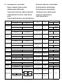
NEDERLANDS
7
ENGLISH
16
DEUTSCH
25
FRANÇAIS
34
ESPAÑOL
43
ITALIANO
52
DANSK
61
SVENSKA
70
NORSK
79
SUOMEKSI
88
POLSKI
97
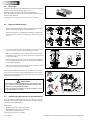
Copyright © 2019 Vetus b.v. Schiedam Holland
BOW22024D
220 kgf - ø 300 mm
020529.06
Bedieningshandleiding en installatie instructies
Bedienungshandbuch und Einbauanleitung
Manuel d’utilisation et instructions d’installation
Manual de manejo y instrucciones de instalación
Manuale per l’uso e istruzioni per l’installazione
Betjeningsvejledning og installations instruktioner
Bruksanvisning och monteringsinstruktioner
Bruksanvisning og installasjonsinstrukser
Käyttö- ja asennusohje
Instrukcja obsługi oraz instalacji
Operation manual
and installation instructions

vetus® Operation manual and installation instructions bow thruster BOW22024D
Naam en adres eigenaar Owner’s Name and Address
Name und Adresse des Halters Nom et adresse du propriétaire
Nombre y dirección del propietario Nome e indirizzo del proprietario
Ejerens navn og adresse Ägarens namn och adress
Eierens navn og adresse Omistajan nimi ja osoite
Nazwisko (nazwa) i adres właściciela
. . . . . . . . . . . . . . . . . . . . . . . . . . . . . . . . . . . . . . . . . . . . . . . . . . . . . . . . . . . . . . . . . . . . . . . . . . . . . . . . . . . . . . . . . . . .
. . . . . . . . . . . . . . . . . . . . . . . . . . . . . . . . . . . . . . . . . . . . . . . . . . . . . . . . . . . . . . . . . . . . . . . . . . . . . . . . . . . . . . . . . . . .
. . . . . . . . . . . . . . . . . . . . . . . . . . . . . . . . . . . . . . . . . . . . . . . . . . . . . . . . . . . . . . . . . . . . . . . . . . . . . . . . . . . . . . . . . . . .
. . . . . . . . . . . . . . . . . . . . . . . . . . . . . . . . . . . . . . . . . . . . . . . . . . . . . . . . . . . . . . . . . . . . . . . . . . . . . . . . . . . . . . . . . . . .
. . . . . . . . . . . . . . . . . . . . . . . . . . . . . . . . . . . . . . . . . . . . . . . . . . . . . . . . . . . . . . . . . . . . . . . . . . . . . . . . . . . . . . . . . . . .
Boegschroeftype, serienummer Thruster model, Serial Number
Bugstrahlrudertyp, Seriennummer Type de propulseur d'étrave, numéro de série
Tipo de hélice de proa, número de serie Tipo di propulsore di prua, numero di serie
Bogpropeller type, serienummer Bogpropeller typ, serienummer
Baugfremdriftstype, serienummer Baugfremdriftstype, serienummer
Typ steru dziobowego, numer seryjny
. . . . . . . . . . . . . . . . . . . . . . . . . . . . . . . . . . . . . . . . . . . . . . . . . . . . . . . . . . . . . . . . . . . . . . . . . . . . . . . . . . . . . . . . . . . .
. . . . . . . . . . . . . . . . . . . . . . . . . . . . . . . . . . . . . . . . . . . . . . . . . . . . . . . . . . . . . . . . . . . . . . . . . . . . . . . . . . . . . . . . . . . .
. . . . . . . . . . . . . . . . . . . . . . . . . . . . . . . . . . . . . . . . . . . . . . . . . . . . . . . . . . . . . . . . . . . . . . . . . . . . . . . . . . . . . . . . . . . .
. . . . . . . . . . . . . . . . . . . . . . . . . . . . . . . . . . . . . . . . . . . . . . . . . . . . . . . . . . . . . . . . . . . . . . . . . . . . . . . . . . . . . . . . . . . .
. . . . . . . . . . . . . . . . . . . . . . . . . . . . . . . . . . . . . . . . . . . . . . . . . . . . . . . . . . . . . . . . . . . . . . . . . . . . . . . . . . . . . . . . . . . .
Zorg er voor dat de eigenaar van het schip over deze handleiding kan beschikken.
Make sure that the user of the vessel is supplied with the owner’s manual.
Sorgen Sie dafür, daß dem Schiseigner die Gebrauchsanleitung bereitgestellt wird.
Veillez à ce que le propriétaire du bateau puisse disposer du mode d’emploi.
Asegurarse de que el propietario de la embarcación puede disponer de las instrucciones para el usuario.
Assicurarsi che il proprietario dell’imbarcazione disponga del manuale.
Sørg for, at denne brugsanvisning er til rådighed for skibets ejer.
Se till att båtens ägare har tillgång till bruksanvisningen.
Sørg for at skipets eier kan disponere over bruksanvisningen.
Käyttöohje tulee olla alusta käyttävien henkilöiden käytettävissä.
Upewnić się, że użytkownik statku jest zaopatrzony w instrukcję obsługi.
2 020529.06
BOW22024D - 220 kgf - ø 300 mm - 24 Volt

vetus® Operation manual and installation instructions bow thruster BOW22024D
020529.06 3
1 Inleiding........................... 7
2 Veiligheid
......................... 7
3 Gebruik
............................ 7
4 Installatieaanbevelingen
........ 8
4.1 Opstelling van de tunnelbuis
..... 8
4.2 Opstelling boegschroef in
tunnelbuis
......................... 8
4.3 Overgang van tunnelbuis naar
scheepsromp
...................... 9
4.4 Spijlen in de tunnelbuis-
openingen
......................... 9
4.5 Aanbrengen van de tunnelbuis
10
4.6 Aanbrengen van de gaten in de
tunnelbuis
....................... 10
4.7 Bescherming van de
boegschroef tegen corrosie
.... 10
5 Inbouw
.......................... 11
5.1 Voorbereiding
................... 11
5.2 Montage staartstuk en
tussenens
...................... 11
5.3 Eindmontage
.................... 12
6 Elektrische installatie
........... 13
6.1 De keuze van de accu
........... 13
6.2 Hoofdschakelaar
................ 13
6.3 Hoofdstroomkabels (accukabels)
13
6.4 Aansluiten hoofdstroomkabels
. 13
6.5 Zekeringen
...................... 14
6.6 Boegschroefbedieningen
....... 14
6.7 Tijdvertraging bij omkeren van
de draairichting
................. 14
7 Storingen
........................ 15
8 Technische gegevens
........... 15
Inhoud Content Inhalt
1 Introduction .................... 16
2 Safety
............................ 16
3 Use
............................... 16
4 Installation recommendations
17
4.1 Positioning of the thruster tunnel
17
4.2 Positioning of the bow thruster
in the thrust-tunnel
............. 17
4.3 Connection of thrust tunnel to
ship’s hull
........................ 18
4.4 Grid bars in the tunnel openings
18
4.5 Installation of the thrust tunnel
19
4.6 Drilling the holes in the thrust-
tunnel
............................ 19
4.7 Protection of the bow thruster
against corrosion
................ 19
5 Installation
. . . . . . . . . . . . . . . . . . . . . . 20
5.1 Preparation
...................... 20
5.2 Installation tailpiece and
intermediate ange
............. 20
5.3 Final assembly
................... 21
6 Electrical installation
........... 22
6.1 Choice of battery
................ 22
6.2 Main switch
...................... 22
6.3 Main power cables (battery
cables)
........................... 22
6.4 Connecting the main power
cables
............................ 22
6.5 Fuses
............................. 23
6.6 Bow thruster control panels
.... 23
6.7 Delay when reversing the
thrust direction
.................. 23
7 Trouble shooting
............... 24
8 Technical data
................... 24
9 Principle dimensions
.......... 106
10 Battery capacity, battery
cables
........................... 107
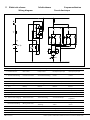
11 Wiring diagram
................ 108
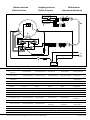
11.1 Simultaneous operation of two
bow thrusters with one panel.. 110
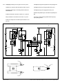
11.2 Series-parallel switch .......... 111
9 Hoofdafmetingen
..............106
10 Accucapaciteit, accukabels
....107
11 Elektrisch schema
..............108
11.1 Gelijktijdige bediening van 2
boegschroeven met 1 paneel.. 110
11.2 Serie-parallelschakelaar ....... 111
1 Einleitung
....................... 25
2 Sicherheitsbestimmungen
.... 25
3 Gebrauch
........................ 25
4 Einbauhinweise
................. 26
4.1 Aufstellung vom tunnelrohr
.... 26
4.2 Aufstellung der Bugschraube
ins Tunnelrohr
................... 26
4.3 Übergang vom tunnelrohr zum
schisrumpf
..................... 27
4.4 Gitterstäbe in den
Tunnelrohrönungen
........... 27
4.5 Anbringen vom Tunnelrohr
..... 28
4.6 Anbringen der Löcher ins
Tunnelrohr
....................... 28
4.7 Korrosionsschutz der
bugschraube
.................... 28
5 Einbau
........................... 29
5.1 Vorbereitung
.................... 29
5.2 Befestigung des
Unterwasserteils und des
Zwischenansches
.............. 29
5.3 Endmontage
..................... 30
6 Elektrische Installation
......... 31
6.1 Wahl des Akku
................... 31
6.2 Hauptschalter
................... 31
6.3 Hauptstromkabel (Akkukabel)
.. 31
6.4 Anschließen der
Hauptstromkabel
................ 31
6.5 Sicherungen
..................... 32
6.6 Bugschrauben-
Bedienungselemente
........... 32
6.7 Zeitverzögerung bei Umkehr
der Drehrichtung
................ 32
7 Störungen
....................... 33
8 Technische daten
............... 33
9 Hauptabmessungen
........... 106
10 Akkukapazität, Akkukabel
.... 107
11 Schaltschema
.................. 108
11.1 Gleichzeitige Bedienung von
zwei Bugschrauben mit einem
Armaturenbrett ............... 110
11.2 Serien-/Parallelschalter ........ 111
Raadpleeg het 'Onderhouds- en garantie-
boek' voor Onderhoud.
Consult the ‘Maintenance and Warranty
Book’ for Maintenance.
Zur Wartung vgl. das „Wartungs- und Ga-
rantiebuch“.

vetus® Operation manual and installation instructions bow thruster BOW22024D
4 020529.06
9 Dimensioni principali ......... 106
10 Capacità della batteria e cavi
della batteria
................... 107
11 Schema elettrico
............... 108
11.1 Comando contemporaneo di 2
eliche di prua mediante 1 solo
pannello ...................... 110
11.2 Interruttore serie-parallelo..... 112
9 Dimensiones principales
...... 106
10 Capacidad de las baterías,
cables de baterías
............. 107
11 Esquema eléctrico
............. 108
11.1 Manejo simultáneo de 2
tornillos de retención con 1
panel ......................... 110
11.2 Interruptor paralelo en serie ... 112
9 Dimensions principales
........106
10 Capacité de la batterie, câbles
de batterie
..................... 107
11 Circuit electrique
...............108
11.1 Commande simultanée de 2
hélices d’étrave avec 1 panneau 110
11.2 Coupleur série - parallèle ...... 111
1 Introduction
.................... 34
2 Sécurité
......................... 34
3 Emploi
........................... 34
4 Recommandations
............. 35
4.1 Position de la tuyere
............ 35
4.2 Position de l’hélice d’étrave
dans la tuyere
.................... 35
4.3 Adaption de la tuyère à l’étrave
. 36
4.4 Barres dans les ouvertures de la
tuyère
............................ 36
4.5 Installation de la tuyère
. . . . . . . . . 37
4.6 Percer les trous dans la tuyère
.. 37
4.7 Protection de l’helice d’etrave
contre la corrosion
.............. 37
5 Installation
. . . . . . . . . . . . . . . . . . . . . . 38
5.1 Préparatifs
....................... 38
5.2 Montage de l’embase et de la
bride intermédiaire
.............. 38
5.3 Montage nal
.................... 39
6 Installation électrique
.......... 40
6.1 Le choix de la batterie
........... 40
6.2 Interrupteur principal
. . . . . . . . . . . 40
6.3 Câbles du courant principal
(câbles de la batterie)
........... 40
6.4 Raccordement des ls de
courant principal
................ 40
6.5 Fusibles
.......................... 41
6.6 Fonctionnement de l’hélice
d’étrave
.......................... 41
6.7 Temporisation lors de
changement de sens de rotation
41
7 Pannes
........................... 42
8 Renseignements techniques
.. 42
1 Introducción
.................... 43
2 Seguridad
....................... 43
3 Uso
............................... 43
4 Recomendaciones
.............. 44
4.1 Situar el conducto de propulsión
44
4.2 Situar la hélice de proa en el
conducto de propulsión
........ 44
4.3 Acoplamiento del conducto de
propulsión al casco
.............. 45
4.4 Barras en los oricios del
conducto de propulsión
........ 45
4.5 Instalación del conducto de
propulsión
....................... 46
4.6 Perforación de los oricios en el
conducto de propulsión
........ 46
4.7 Protección de la hélice de proa
contra la corrosión
.............. 46
5 Incorporación
................... 47
5.1 Preparativos
..................... 47
5.2 Instalación de la parte posterior
y la brida intermedia
............ 47
5.3 Montaje nal
.................... 48
6 Instalación eléctrica
. . . . . . . . . . . . 49
6.1 La elección de batería
........... 49
6.2 Interruptor principal
............ 49
6.3 Cables de corriente principal
(cables de batería)
............... 49
6.4 Conexión de los cables de
corriente principal
............... 49
6.5 Fusibles
.......................... 50
6.6 Controles de la hélice de proa
.. 50
6.7 Retardo en inversión de
dirección de giro
................ 50
7 Fallos
............................ 51
8 Especicaciones técnicas
...... 51
Sommaire Índice Indice
1 Introduzione .................... 52
2 Sicurezza
........................ 52
3 Funzionamento
................. 52
4 Suggerimenti per l’installazione
53
4.1 Collocazione del tunnel
......... 53
4.2 Collocazione dell’elica di prua
nel tunnel
........................ 53
4.3 Montaggio del tunnel allo scafo
54
4.4 Sbarre nelle aperture del tunnel
54
4.5 Installazione del tunnel
......... 55
4.6 Come praticare i fori nel tunnel
. 55
4.7 Protezione dell’elica di prua
contro la corrosione
............. 55
5 Installazione
.................... 56
5.1 Operazioni preliminari
.......... 56
5.2 Montaggio del piedino e della
angia intermedia
............... 56
5.3 Assemblaggio nale
............ 57
6 Collegamento elettrico
......... 58
6.1 La scelta della batteria
.......... 58
6.2 Interruttore principale
.......... 58
6.3 Cavi (della batteria)
.............. 58
6.4 Allacciamento dei cavi elettrici
principali
......................... 58
6.5 Fusibili
........................... 59
6.6 Comandi per elica di prua
...... 59
6.7 Ritardo dopo l’inversione della
rotazione
........................ 59
7 Guasti
............................ 60
8 Dati tecnici
...................... 60
Consulter le « Manuel d'entretien et de ga-
rantie » pour eectuer les travaux de main-
tenance.
Para el mantenimiento, consulte el «Ma-
nual de mantenimiento y garantía».
Per la manutenzione consultare il "Manuale
di manutenzione e garanzia".

vetus® Operation manual and installation instructions bow thruster BOW22024D
020529.06 5
9 Mål.............................. 106
10 Batteriets kapacitet,
batterikabler
................... 107
11 Elektrisk skema
................ 108
11.1 Samtidig betjening af
2 bovpropeller med 1
betjeningspanel............... 110
11.2 Serie-/parallelafbryder ........ 112
1 Indledning
...................... 61
2 Sikkerhed
....................... 61
3 Brug
.............................. 61
4 Anbefalinger til montering
.... 62
4.1 Placering af tunnelrøret
......... 62
4.2 Placering af bovskruen i
tunnelrøret
...................... 62
4.3 Overgang fra tunnelrør til
skibsskrog
....................... 63
4.4 Stænger i tunnelrørsåbningen
. 63
4.5 Installering af tunnelrøret
....... 64
4.6 Boring af hullerne i tunnelrøret
. 64
4.7 Beskyttelse af bovskruen mod
tæring
............................ 64
5 Indbygning
...................... 65
5.1 Forberedelse
..................... 65
5.2 Montering af endestykke og
mellemange
.................... 65
5.3 Slutmontering
................... 66
6 Elektrisk installation
............ 67
6.1 Valg af batteri
.................... 67
6.2 Hovedafbryder
.................. 67
6.3 Hovedstrømskaber
(batterikabler)
................... 67
6.4 Tilslutning af hovedstrømkabler
67
6.5 Sikringer
......................... 68
6.6 Kontrolpaneler til bovskruer
.... 68
6.7 Tidsforsinkelse ved ændring af
rotationsretningen
.............. 68
7 Driftsfejl
......................... 69
8 Tekniske specikationer
....... 69
Indhold Innehåll Innhold
1 Inledning ........................ 70
2 Säkerhet
......................... 70
3 Användning
..................... 70
4 Rekommendationer för
montering
....................... 71
4.1 Tunnelns placering
.............. 71
4.2 Bogpropellerns placering i
tunnelröret
...................... 71
4.3 Tunnelns övergång till båtens
skrov
............................. 72
4.4 Gallerstänger i rörets öppningar
72
4.5 Montering av tunnelröret
....... 73
4.6 Att göra hål i tunnelröret
........ 73
4.7 Bogpropellerns rostskydd
...... 73
5 Montering
....................... 74
5.1 Förberedelser
.................... 74
5.2 Montering av växelhus och
mellanäns
...................... 74
5.3 Slutmontering
................... 75
6 Elektrisk anslutning
............ 76
6.1 Val av batteri
..................... 76
6.2 Huvudströmbrytare
............. 76
6.3 Drivströmkablar (batterikablar)
. 76
6.4 Ansluta huvudströmkablar
..... 76
6.5 Säkringar
......................... 77
6.6 Manövrering av bogpropellern
. 77
6.7 Tidsfördröjning vid vändning
av rotationsriktningen
.......... 77
7 Felsökning
...................... 78
8 Tekniska uppgifter
............. 78
1 Innledning ...................... 79
2 Sikkerhet
........................ 79
3 Bruk
.............................. 79
4 Anbefalinger for installasjon
.. 80
4.1 Plassering av tunnelrøret
....... 80
4.2 Plassering av baugpropellen i
tunnelrøret
...................... 80
4.3 Overgang fra tunnelrør til
skipsskrog
....................... 81
4.4 Stenger i tunnelrøråpningen
... 81
4.5 Installering av tunnelrøret
...... 82
4.6 Boring av hullene i tunnelrøret
. 82
4.7 Beskyttelse av baugpropellen
mot korrosjon
................... 82
5 Innbygging
...................... 83
5.1 Forberedelser
.................... 83
5.2 Montering av halestykke og
mellomens
..................... 83
5.3 Sluttmontasje
................... 84
6 Elektrisk installasjon
........... 85
6.1 Valg av batteri
................... 85
6.2 Hovedbryter
..................... 85
6.3 Hovedstrømkabler (batterikabler)
85
6.4 Koble til hovedstrømkabler
..... 85
6.5 Sikringer
......................... 86
6.6 Kontroll av baugpropell
......... 86
6.7 Tidsforsinkelse ved endring av
dreieretningen
.................. 86
7 Feil
............................... 87
8 Tekniske data
................... 87
9 Huvudmått
..................... 106
10 Batterikapacitet,
batterikablar
................... 107
11 Kopplingsschema
............. 108
11.1 Samtidig manövrering av 2
bogpropellrar med 1 panel .... 110
11.2 Serie-parallellomkopplare ..... 112
9 Viktigste mål
. . . . . . . . . . . . . . . . . . . . 106
10 Batterikapasitet, batterikabler
107
11 Elektrisk skjema
................108
11.1 Samtidig betjening av 2
baugpropeller med 1 panel.... 110
11.2 Serie-parallellbryter ........... 113
Se ”Underhålls- och garantiboken” för un-
derhåll.
Se «Vedlikeholds- og garantiboken» for
vedlikehold.
Se «Vedlikeholds- og garantiboken» for
vedlikehold.

vetus® Operation manual and installation instructions bow thruster BOW22024D
6 020529.06
9 Päämitat........................ 106
10
Akkukapasiteetti,
akkukaapelit
..................107
11 Sähkökaavio
................... 108
11.1 Kahden keukapotkurin ohjaus
samanaikaisesti yhdellä
panelilla....................... 110
11.2 Sarja/rinnakkaiskytkin ......... 113
9 Główne wymiary
............... 106
10 Pojemność akumulatora,
kable akumulatora
............ 107
11 Schemat okablowania
.........108
11.1 Jednoczesna obsługa dwóch
pędników dziobowych przy
użyciu jednego panelu ........ 110
11.2 Przełącznik szeregowo-
równoległy .................. 113
1 Esipuhe
.......................... 88
2 Turvallisuus
..................... 88
3 Käyttö
........................... 88
4 Sijoitussuosituksia
.............. 89
4.1 Keulapotkurin sijoittaminen
.... 89
4.2 Keulapotkurin sijoittaminen
tunneliin
......................... 89
4.3 Tunnelin liittäminen aluksen
runkoon
.......................... 90
4.4 Ristikko tunnelin suulla
......... 90
4.5 Tunnelin asennus
................ 91
4.6 Asennusreikien tekeminen
tunneliin
......................... 91
4.7 Keulapotkurin suojaaminen
korroosiolta
...................... 91
5 Asennus
......................... 92
5.1 Esivalmistelu
..................... 92
5.2 Kulmavaihteiston ja
moottorilaipan asennus
......... 92
5.3 Lopullinen asennus
............. 93
6 Sähköasennukset
............... 94
6.1 Akun valinta
..................... 94
6.2 Pääkytkin
........................ 94
6.3 Päävirtakaapelit (akkukaapelit)
. 94
6.4 Päävirtakaapelien liitäntä
....... 94
6.5 Sulakkeet
........................ 95
6.6 Keulapotkurin ohjaus
........... 95
6.7 Aikaviive ajosuuntaa
vaihdettaessa
.................... 95
7 Vian etsintä
..................... 96
8 Tekniset tiedot
.................. 96
1 Wprowadzenie
.................. 97
2 Bezpieczeństwo
................ 97
3 Użytkowanie
.................... 97
4 Zalecenia dotyczące instalacji
. 98
4.1 Pozycjonowanie tunelu silnika
sterującego
. . . . . . . . . . . . . . . . . . . . . . 98
4.2 Pozycjonowanie silników
sterujących w tunelu sterującym
98
4.3 Podłączenie tunelu sterującego
do kadłuba okrętu
............... 99
4.4 Kraty w otworach tunelu
........ 99
4.5 Instalacja silnika sterującego
.. 100
4.6 Wiercenie otworów w tunelu
.. 100
4.7 Zabezpieczenie silnika
sterującego przed korozją
..... 100
5 Instalacja
....................... 101
5.1 Przygotowanie
................. 101
5.2 Instalacja części końcowej i
kołnierza pośredniego
......... 101
5.3 Montaż końcowy
............... 102
6 Instalacja elektryczna
......... 103
6.1 Wybór baterii
................... 103
6.2 Przełącznik główny
............. 103
6.3 Główne kable zasilające (kable
akumulatorowe)
................ 103
6.4 Podłączanie głównych kabli
zasilających
..................... 103
6.5 Bezpiecznik
..................... 104
6.6 Działanie dziobowego silnika
sterującego
. . . . . . . . . . . . . . . . . . . . . 104
6.7 Opóźnienie podczas cofania
... 104
7 Rozwiązywanie problemów
.. 105
8 Dane techniczne
............... 105
Sisältö Spis tresci
Katso huolto-ohjeet Huolto- ja takuukirjas-
ta.
Informacje na temat konserwacji można
znaleźć w „Książce konserwacji i gwarancji”.

vetus® Operation manual and installation instructions bow thruster BOW22024D
020529.06 7
1 Inleiding
Deze handleiding geeft richtlijnen voor de inbouw en het gebruik
van de Vetus boegschroef ‘BOW22024D’.
De kwaliteit van de inbouw is maatgevend voor de betrouwbaarheid
van de boegschroef. Bijna alle storingen die naar voren komen zijn
terug te leiden tot fouten of onnauwkeurigheden bij de inbouw. Het
is daarom van het grootste belang de in de installatieinstructies ge-
noemde punten tijdens de inbouw volledig op te volgen en te con-
troleren.
Eigenmachtige wijzigingen aan de boegschroef sluiten de aan-
sprakelijkheid van de fabriek voor de daaruit voortvloeiende scha-
de uit.
Afhankelijk van de windvang, de waterverplaatsing en de vorm van
het onderwaterschip zal de door de boegschroef geleverde stuw-
kracht op ieder schip een verschillend resultaat geven.
De nominaal opgegeven stuwkracht is alleen haalbaar onder opti-
male omstandigheden:
• Zorg tijdens gebruik voor een correcte accuspanning.
• De installatie is uitgevoerd met in achtname van de aanbevelin-
gen zoals gegeven in de ‘Installatieaanbevelingen voor boeg-
schroeven’, in het bijzonder met betrekking tot:
- Voldoende grootte van de draaddoorsnede van de accukabels,
om zodoende het spanningsverlies zo veel mogelijk beperkt te
houden.
- De wijze waarop de tunnelbuis op de scheepsromp is aange-
sloten.
- Spijlen in de tunnelbuis-openingen.
Deze spijlen alleen dan zijn aangebracht indien dit strikt nood-
zakelijk is (indien regelmatig in sterk vervuilde wateren wordt
gevaren).
- Deze spijlen volgens de aanbevelingen zijn uitgevoerd.
Het gevolg geven aan de hierna volgende aanbevelingen zal resulte-
ren in een langere levensduur en in betere prestaties van uw boeg-
schroef.
• Raadpleeg voor onderhoud het meegeleverde ‘Onderhouds- en
garantieboek’. Art. code 020901.01.
• Laat de boegschroef nooit langdurig draaien; in verband met
warmteontwikkeling in de elektromotor is de maximale inschakel-
duur beperkt.
Na een periode van draaien moet de motor afkoelen.
Let op
De maximale aaneengesloten gebruiksinschakelduur en de
stuwkracht zoals gespeciceerd bij de technische gegevens
zijn gebaseerd op de aanbevolen accucapaciteiten en ac-
cuaansluitkabels.
Bij toepassing van aanzienlijke grotere accu’s in combinatie
met zeer korte accuaansluitkabels met een aanzienlijke gro-
tere doorsnede dan aanbevolen zal de stuwkracht toenemen.
Verlaag in dat geval de maximale inschakelduur om schade
aan de motor te voorkomen.
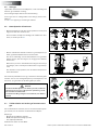
2 Veiligheid
WaarschuWing
Let bij het gebruik van de boegschroef op het gevaar voor zwem-
mers of lichte bootjes welke zich in de onmiddellijke nabijheid
van de boegschroefbuis-uitstroomopeningen bevinden.
Geef de veiligheidsaanwijzingen door aan andere personen die de
boegschroef bedienen.
Algemene regels en wetten met betrekking tot veiligheid en ter voor-
koming van ongelukken dienen ook in acht te worden genomen.
• Raak tijdens bedrijf van de boegschroef nooit bewegende delen
aan.
• Raak nooit hete delen van de boegschroef aan en plaats nooit
brandbare materialen in de nabijheid van de boegschroef.
• Stop de boegschroef altijd alvorens onderdelen van de boeg-
schroef te controleren of af te stellen.
• Neem altijd de accupolen los tijdens onderhoudswerkzaamhe-
den.
• Voer onderhoudswerkzaamheden veilig uit door uitsluitend pas-
send gereedschap toe te passen.
• Zet altijd de hoofdschakelaar uit indien de boegschroef langdurig
niet gebruikt wordt.
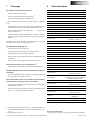
3 Gebruik
• Schakel de accu-hoofdschakelaar in.
• Raadpleeg de met de bedieningspanelen meegeleverde handlei-
ding voor het gebruik van de boegschroef.
Schakel niet in één beweging van bakboord naar stuurboord
of andersom, maar geef de elektromotor de tijd om tot stil-
stand te komen, voordat hij in een andere richting moet gaan
draaien.
Voorzichtig
Indien 2 bedieningspanelen zijn geïnstalleerd; bedien de boeg-
schroef dan nooit gelijktijdig vanaf beide panelen.
• Schakel de accu-hoofdschakelaar uit, indien U van boord gaat.
• Houd er rekening mee dat van de koolborstels in de motor (zwart)
stof vrijkomt. Berg geen kwetsbare uitrusting op in de nabijheid
van de boegschroefmotor.
Zorg er voor dat de eigenaar van het schip over deze
handleiding kan beschikken.
NEDERLANDS

vetus® Operation manual and installation instructions bow thruster BOW22024D
8 020529.06
A
D
A
A
D
B
=
=
D = 300 mm
A = 150 mm
B = 600...1200 mm
180º
<60º
Max. niveau
bilge-water
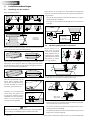
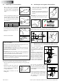
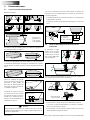
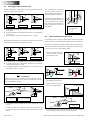
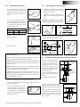
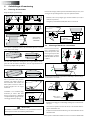
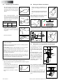
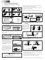
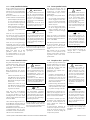
4.2 Opstelling boegschroef in tunnelbuis
Bij het kiezen van de
plaats waar de boeg-
schroef in de tunnelbuis
wordt geplaatst dient er
rekening mee te worden
gehouden dat de schroef
NIET buiten de tunnel-
buis mag uitsteken.
- De boegschroef kan in verschillende standen worden ingebouwd,
van horizontaal tot vertikaal naar boven.
- Als de motor horizontaal of schuin wordt opgesteld dan is onder-
steuning absoluut noodzakelijk.
- De elektromotor dient steeds boven het maximale niveau van het
bilge-water te worden opgesteld.
De schroef dient zich bij voorkeur op de hartlijn van het schip te be-
vinden, maar moet van buiten wel altijd bereikbaar zijn.
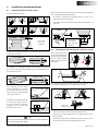
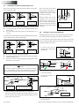
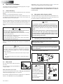
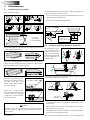
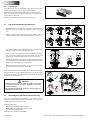
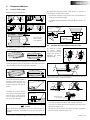
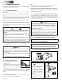
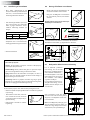
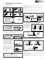
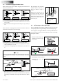
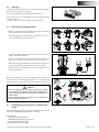
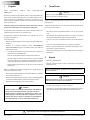
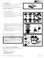
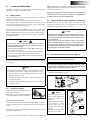
4 Installatieaanbevelingen
Enige inbouwvoorbeelden:
Om een optimaal resultaat te bereiken dient de tunnelbuis zover mo-
gelijk vooraan in het schip te worden geplaatst.
Opstelling 2
boegschroeven
in catamaran
Indien behalve de bewegingen van de boeg van het schip ook de
bewegingen van de spiegel in zijwaartse richting beheerst moeten
kunnen worden kan ook een ‘boeg’schroef ter hoogte van de achter-
zijde van het schip worden geïnstalleerd.
Plaats bij een planerend schip de
tunnel, indien mogelijk, dusda-
nig dat deze in plané boven wa-
ter komt, waardoor er van enige
weerstand geen sprake meer is.
Installatie van 2 boegschroeven
achter elkaar voor grotere sche-
pen. Bij deze opstelling kunnen,
afhankelijk van weersomstandig-
heden e.d., één of beide boeg-
schroeven worden gebruikt.
tip:
Wij raden de installatie van 2 boegschroeven in één (1) tunnelbuis
af; er wordt geen verdubbeling van de stuwkracht bereikt!
Bij het kiezen van de positie waar de tunnelbuis wordt geplaatst
dient voor een optimaal resultaat met het volgende rekening te wor-
den gehouden:
- De in de tekening aangegeven maat A dient minimaal 0,5 x D (D is
de buisdiameter) te bedragen.
- De lengte van de tunnelbuis (afmeting B) dient 2 x D tot 4 x D te
bedragen.
4.1 Opstelling van de tunnelbuis
NEDERLANDS

vetus® Operation manual and installation instructions bow thruster BOW22024D
020529.06 9
DL
=
α
α : min. 0º
max. 15º
D = 300 mm
L = 300 ... 900 mm
A
D
D = 300 mm R = 30 mm
C = 30 ... 45 mm
R
R
B
C
C
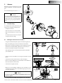
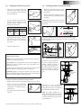
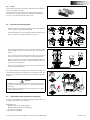
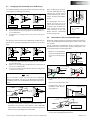
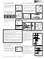
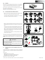
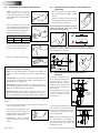
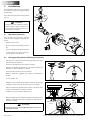
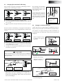
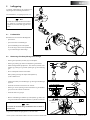
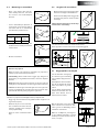
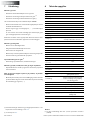
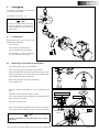
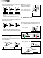
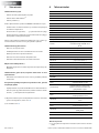
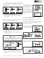
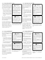
4.3 Overgang van tunnelbuis naar scheepsromp
tip:
De wijze waarop de tunnelbuis overgaat in de scheepsromp is van
grote invloed op de door de boegschroef geleverde stuwkracht
en op de rompweerstand tijdens de normale vaart.
Met een directe overgang van de tunnelbuis op de scheepsromp,
zonder schelp, worden redelijke resultaten behaald.
A Een directe overgang op de scheepsromp kan scherp worden
gemaakt.
B Beter is het de overgang af te ronden met een straal ‘R’ van ca. 0,1
x D.
C Nog beter is het om schuine zijden ‘C’ van 0,1 à 0,15 x D toe te
passen.
D
R
R
C
A B C
D = 300 mm R = 30 mm
C = 30 ... 45 mm
Met een schelp in de overgang van de tunnelbuis op de scheeps-
romp wordt een lagere rompweerstand tijdens de normale vaart
verkregen.
Indien de overgang van tunnel-
buis op scheepsromp met een
schuine zijde wordt uitgevoerd
dient deze volgens de tekening
te worden uitgevoerd.
Maak de schuine zijde (C) 0,1 à
0,15 x D lang en zorg er voor dat
de hoek die de tunnelbuis maakt
met de schuine zijde gelijk is aan
de hoek die de scheepsromp
maakt met de schuine zijde.
C
C
β
γ
γ
β
C = 30...45 mm
D = 300 mm
β = β
γ = γ
Scherp
A De overgang met schelp op de scheepsromp kan scherp worden
gemaakt.
B Beter is het de overgang met schelp, af te ronden met een straal
‘R’ van ca. 0,1 x D.
C Het beste is een overgang met schelp, met een schuine zijde ‘C’
van 0,1 à 0,15 x D.
- Kies de lengte ‘L’ voor een schelp tussen 1 x D en 3 x D.
- Een schelp dient zodanig in de scheepsromp te zijn opgenomen
dat de hartlijn van de schelp samenvalt met de te verwachten
vorm van de boeggolf.
NEDERLANDS
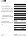
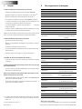
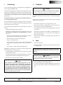
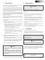
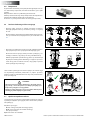
4.4 Spijlen in de tunnelbuis-openingen
Hoewel de stuwkracht hierdoor ongunstig wordt beïnvloed kunnen,
ter bescherming van de schroef, in de openingen van de tunnelbuis
spijlen worden aangebracht.
Om het nadelige eect hiervan op de stuwkracht en op de romp-
weerstand tijdens de normale vaart zoveel mogelijk te beperken
dient met het volgende rekening te worden gehouden:
4 x
300 mm
- De spijlen moeten een rechthoekige doorsnede hebben.
- Pas geen ronde spijlen toe.
- De spijlen moeten zodanig zijn opgesteld dat ze loodrecht staan
op de te verwachten golfvorm.
ø ...
3 mm
min. 20 mm
max. 40 mm
ca. 0,7 x 0,7 mm
=
α
α : min. 0º
max. 15º
90º
Overlapping
- Breng niet meer spijlen aan
per opening dan in de teken-
ing is aangegeven.
- De spijlen moeten een ze-
kere overlapping te hebben.

vetus® Operation manual and installation instructions bow thruster BOW22024D
10 020529.06
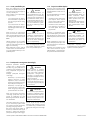
ø 300 mm
FOKKERSTRAAT 571 - 3125 BD SCHIEDAM - HOLLAND
TEL.: +31 0(0)88 4884700 - [email protected] - www.vetus.com
vetus b.v.
Printed in the Netherlands
010121.01 2019-07
3
50 (1
31
/
32
”)
136 (5
3
/
8
”)
ø 12.5 (
1
/
2
”)
ø 12.5 (
1
/
2
”)
ø 60 (2
3
/
8
”)
50 (1
31
/
32
”)
Schaal 1:1
Scale 1:1
Maßstab 1:1
Echelle 1:1
Escala 1:1
Scala 1:1
Skala 1:1
Skala 1:1
Målestokk 1:1
Suhde 1:1
Skala 1:1
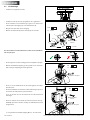
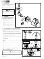
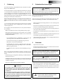
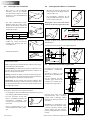
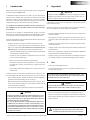
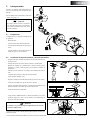
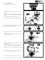
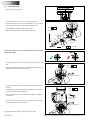
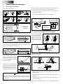
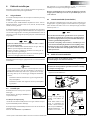
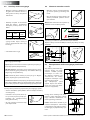
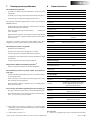
4.6 Aanbrengen van de gaten in de tunnelbuis
- Teken, met behulp van de tussenens,
de plaats af waar de boegschroef ge-
monteerd moet worden.
- Gebruik de meegeleverde boormal om
de juiste plaats van de te boren gaten te
bepalen.
Belangrijk: Het gatenpatroon dient exact
op de hartlijn van de tunnelbuis te liggen.
Raadpleeg de boormal voor de afmetingen van de te boren gaten.
Breng de gaten aan in de tunnelbuis en werk deze braamvrij af.
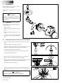
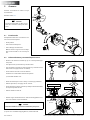
4.7 Bescherming van de boegschroef tegen corrosie
Om corrosieproblemen te
voorkomen dient absoluut
geen koperoxide bevattende
anti-fouling te worden aange-
bracht.
Kathodische bescherming is
absoluut noodzakelijk voor het
behoud van alle metalen delen
die zich onder water bevinden.
Om het staartstuk van de boeg-
schroef te beschermen tegen
corrosie is het staartstuk reeds
voorzien van een zinkanode.
Bij een stalen of aluminium tunnel-
buis kan vermindering van corrosie
worden bereikt door het volledig ge-
isoleerd opstellen van het staartstuk in
de tunnelbuis.
N.B. De meegeleverde pakkingen zijn
reeds elektrisch isolerend. De boutjes
en de schacht dienen echter te wor-
den voorzien van isolatiemateriaal,
b.v. nylon busjes.
Isolatiebus
Pakking
Isolatiebus
Isolatiebus
Polyester tunnelbuis:
Hars: Het voor de polyester tunnelbuis toegepaste hars is iso-
phtaalzure polyesterhars (Norpol PI 2857).
Voorbehandeling: De buitenzijde van de buis moet worden op-
geruwd. Verwijder de volledige toplaag tot op het glasweefsel,
gebruik hiervoor een slijpschijf.
Belangrijk: Behandel de uiteinden van de buis, nadat deze op
lengte is gezaagd, met hars. Hiermee wordt voorkomen dat
vocht in het materiaal naar binnen kan dringen.
Lamineren: Breng als eerste laag, een laag hars aan. Breng een
glasmat aan en impregneer deze met hars, herhaal dit tot een
voldoende aantal lagen is opgebracht.
Een polyester tunnelbuis dient als volgt te worden afgewerkt:
• Ruw de uitgeharde hars/glasmat op. Breng een laag hars (top-
coat) aan.
4.5 Aanbrengen van de tunnelbuis
• Boor 2 gaten in de scheepsromp,
daar waar de hartlijn van de tunnel-
buis moet komen, overeenkomstig
de diameter van het aftekengereed-
schap.
D
• Steek het aftekengereedschap (zelf
te vervaardigen) door beide voorge-
boorde gaten en teken de omtrek
van de tunnelbuis-buitendiameter
op de romp af.
D [mm]
Staal Polyester Aluminium
320 320 320
• Breng de gaten aan, afhankelijk van
het materiaal van de scheepsromp
met een decoupeerzaag of een snij-
brander.
• Monteer de tunnelbuis.
• Behandel de zijde van de buis die
met het water in aanraking komt
met b.v. ‘epoxyverf’ of 2-componen-
ten polyurethaanverf.
• Breng hierna eventueel een anti-
fouling aan.
NEDERLANDS

vetus® Operation manual and installation instructions bow thruster BOW22024D
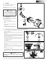
5 Inbouw
Raadpleeg voor het installeren van de tun-
nelbuis hoofdstuk 4 ‘Installatieaanbevelin-
gen'.
Voor hoofdafmetingen zie tek. blz. 106.
Let op
De ruimte waarin de elektromotor van
de boegschroef wordt opgesteld en de
ruimte waarin de accu wordt opgesteld
dienen droog en goed geventileerd te
zijn.
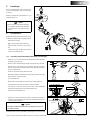
5.1 Voorbereiding
De boegschroef wordt gemonteerd gele-
verd. Voer de volgende handelingen uit:
• Verwijder de schroef.
• Neem de motor los van de tussenens.
• Neem de tussenens los van het staart-
stuk.
De 2 bussen dienen alleen voor transport
en zijn nu niet meer nodig.
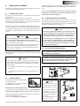
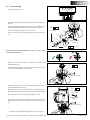
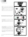
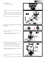
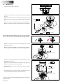
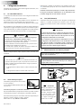
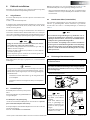
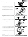
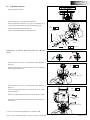
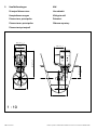
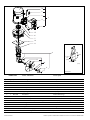
5.2 Montage staartstuk en tussenens
• Zorg dat de kunststof vulplaat (1) op het staartstuk is geplaatst.
• Breng één pakking (2) aan tussen staartstuk en tunnelbuis.
• Breng tussen staartstuk en pakking en tussen pakking en tunnel-
buiswand een afdichtmiddel (polyurethaan* of siliconen) aan.
• Plaats het staartstuk in het gat in de tunnelbuis.
Extra pakkingen dienen om het staartstuk te kunnen uitvullen.
*) b.v. Sikaex®-292.
• Vet het gat in de tussenens in en breng de tussenens op zijn
plaats.
• Controleer nu maat ‘H’, deze moet 49 - 54 mm bedragen.
• Plaats een extra pakking tussen de tunnelbuis en tussenens in-
dien maat ‘H’ kleiner is dan 49 mm.
• Controleer nu nogmaals maat ‘H’.
• Monteer nu de tussenens denitief op het staartstuk, vet de
schroefdraad van de bouten in met ‘outboard gear grease’*) alvo-
rens deze te monteren.
Let op
Controleer op mogelijke lekkage onmiddellijk nadat het schip
te water is gelaten
*) Een geschikt vet is VETUS ‘Shipping Grease’, Art. code: VSG.
1
2
H
H < 49 mm
H = 49 - 54 mm
M12 19
30 - 35 Nm
Outboard Gear
Grease
020529.06 11
NEDERLANDS

vetus® Operation manual and installation instructions bow thruster BOW22024D
De schroef dient nu rondom minimaal 1,5 mm van de tunnelbuis-
wand vrij te lopen.
5.3 Eindmontage
• Controleer nu nogmaals maat ‘H’!
• Vet de ingaande as in met montagepasta; b.v. ‘Molykote® G-n plus’.
• Monteer de exibele koppeling op de ingaande as van het staart-
stuk en borg de koppeling met de borgschroef.
• Vet de as van de elektromotor in met montagepasta; b.v. Moly-
kote® G-n plus’.
• Vet de schroefdraad van de bouten in met ‘outboard gear grease’*)
en monteer de elektromotor op de tussenens.
Let er op dat met één van de bouten ook de relaissteun wordt
bevestigd.
• Draai ter controle met de hand de schroef rond, deze moet ge-
makkelijk zijn rond te draaien, waarbij de elektromotoras wordt
meegenomen.
• Controleer of de spie (1) in de spiegleuf van de as geplaatst is.
• Vet de schroefas in met ‘outboard gear grease’*) en monteer de
schroef (2) met de borgring (3) en de zeskantmoer (4).
• Borg de moer met de lip van de borgring.
• Monteer de zinkanode (5) met de bout (6) op de schroefas.
*) Een geschikt vet is VETUS ‘Shipping Grease’, Art. code: VSG.
M8
12 - 15 Nm
6
Outboard Gear
Grease
Molykote® G-n plus
M8
12 - 15 Nm
4
Molykote® G-n plus
M16 24
20 - 25 Nm
M6
5
5 - 6 Nm
1
2
3
4
5
6
Outboard Gear
Grease
H
H = 49 - 54 mm
12 020529.06
NEDERLANDS

vetus® Operation manual and installation instructions bow thruster BOW22024D
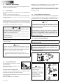
Let op
Voorkom verdraaien van
de bout en moer 1 tijdens
het aansluiten van de ka-
bels.
Houd daarom tijdens het
aandraaien van moer 2
een steeksleutel op moer 1
zonder deze steeksleutel te
verdraaien.
Het aandraaimoment van
moer 2 is 9 - 11 Nm.
9 - 11 Nm
17
1
2
2 x M10
020529.06 13
6 Elektrische installatie
Controleer of de spanning, vermeld op het typeplaatje van de motor,
overeenkomt met de boordspanning.
6.1 De keuze van de accu
De totale accu-capaciteit moet op de grootte van de boegschroef
zijn afgestemd.
Zie pagina 107 voor de toe te passen accucapaciteit.
Wij bevelen Vetus onderhoudsvrije scheepsaccu’s aan; welke lever-
baar zijn in de navolgende grootten : 55 Ah, 70 Ah, 90 Ah, 108 Ah,
120 Ah, 143 Ah, 165 Ah, 200 Ah en 225 Ah.
Ook bevelen wij aan om voor de (elke) boegschroef een aparte accu
of accu’s te gebruiken. De accu(’s) kunnen dan zo dicht mogelijk bij
de boegschroef worden geplaatst; de hoofdstroomkabels kunnen
dan kort zijn en spanningsverliezen door lange kabels worden ver-
meden.
Let op
Pas uitsluitend ‘gesloten’ accu’s toe indien de accu’s in hetzelf-
de compartiment worden geplaatst als de boegschroef.
De Vetus gesloten onderhoudsvrije accu’s type ‘SMF’ en ‘AGM’
zijn hiervoor bij uitstek geschikt.
Bij accu’s die niet ‘gesloten’ zijn kunnen tijdens het laden kleine
hoeveelheden explosief gas kunnen worden geproduceerd.
Vonken bij de koolborstels van de boegschroefmotor kunnen
dit explosieve gas ontsteken.
Gebruik altijd accu’s waarvan type, capaciteit en staat van dienst
overeenkomen.
Voorzichtig
In zeer extreme gevallen, b.v. een accucapaciteit die het 5-vou-
dige of meer is dan geadviseerd, bestaat het gevaar dat perma-
nente schade wordt toegebracht aan een of beide van volgende
asverbindingen:
- de verbinding van motoras naar de ingaande as van het
staartstuk.
- de verbinding van uitgaande as van het staartstuk naar de
schroef.
6.2 Hoofdschakelaar
In de ‘plus-kabel’ moet een hoofdschakelaar
worden opgenomen.
Als schakelaar is een Vetus-accuschakelaar
type BATSW600 zeer geschikt.
6.3 Hoofdstroomkabels (accukabels)
De minimale draaddoorsnede dient op de grootte van de boeg-
schroef te zijn afgestemd en het spanningsverlies tussen de accu’s en
de boegschroef mag niet meer dan 10% van de voedingsspanning
bedragen, raadpleeg de tabel op pagina 107.
Let op
De maximale gebruiksinschakelduur en de stuwkracht zoals
gespeciceerd bij de technische gegevens in de installatie- en
bedieningshandleiding van uw boegschroef zijn gebaseerd
op de aanbevolen accucapaciteiten en accuaansluitkabels.
Bij toepassing van aanzienlijke grotere accu’s in combinatie
met zeer korte accuaansluitkabels met een aanzienlijke gro-
tere doorsnede dan aanbevolen zal de stuwkracht toenemen.
Verlaag in dat geval de maximale inschakelduur om schade
aan de motor te voorkomen.
6.4 Aansluiten hoofdstroomkabels
Let op dat bij het aansluiten van elektrische kabels geen an-
dere elektrische delen los komen.
Controleer na 14 dagen alle elektrische verbindingen. Ten
gevolg van temperatuurschommelingen kunnen elektrische
delen (bijvoorbeeld bouten en moeren) los komen
Hoofdschakelaar met afstandsbediening
In plaats van een accu-hoofdschakelaar kan een op afstand bedien-
de hoofdstroomschakelaar annex noodstop worden geïnstalleerd.
Deze op afstand bediende hoofdstroomschakelaar is leverbaar voor
12 Volt of 24 Volt gelijkspanning.
Vetus art. code: BPMAIN12 resp. BPMAIN24.
NEDERLANDS
N.B. Bij toepassing van een serie-parallelschakelaar (zie pagina 111)
moet de hoofdstroomschakelaar geschikt zijn voor de boordspan-
ning.
Pas een accu-hoofdschakelaar voor 12 Volt toe indien een 24Volt
boegschroef in combinatie met een serie-parallelschakelaar op
een 12 Volt boordnet is aangesloten.
• Sluit de hoofdstroomkabels aan.

vetus® Operation manual and installation instructions bow thruster BOW22024D
Indien bij het proefdraaien blijkt dat de stuwrichting van de boeg-
schroef niet overeen komt met de richtingschakelaar op het bedie-
ningspaneel moeten de blauwe (no.1) en de witte (no.4) draad op het
relais worden omgewisseld.
WaarschuWing
Test de boegschroef niet terwijl het schip uit het water is, ten-
zij u er zich van overtuigd heeft dat iedereen zich op veilige
afstand van de schroeftunnel bevindt.
Laat de boegschroef, terwijl het schip uit het water is, nooit
langer draaien dan 5 seconden.
• Breng de tussenkabel tussen boegschroef en bedieningspaneel
aan in het schip en steek de stekerverbindingen in elkaar.
Indien het noodzakelijk is de tussenkabel door te snijden en weer
te verbinden zorg er dan voor dat de aders weer kleur op kleur
aangesloten worden.
N.B. De kleuren van de aders in de tussenkabel kunnen afwijken
van de draadkleuren zoals toegepast op de boegschroefmotor en
op het bedieningspaneel!
Indien twee stuurstanden aanwezig zijn kan het tweede paneel
op het eerste paneel worden aangesloten.
1
4
1 4
6.6 Boegschroefbedieningen
• Monteer het bedieningspaneel bij de stuurstand. De vrije ruimte
achter het paneel moet minimaal 50 mm bedragen.
Indien 2 boegschroeven gelijktijdig bediend moeten worden, bij-
voorbeeld bij een catamaran, raadpleeg dan het schema op pa-
gina 110.
BPJE2
BPJSE
EZDOCK2
EZDOCKS
BPAJ BPJR
BPSE2
BPSSE
BPJDE2
BPJDSE
BPAS BPSR
6.7 Tijdvertraging bij omkeren van de draairichting
In het geval dat een tijdvertraging gewenst is terwijl een van de on-
derstaande bedieningen wordt toegepast kan een tijdvertragings-
schakelaar worden geïnstalleerd.
Bedieningen:
- BPJSTA, Losse zwenk-schakelaar (Joy-stick),
- BPSM, Bedieningspaneel voor zijmontage,
- FSxx, Drukknop voetschakelaar
Tijdvertraging: Vetus art. code: BPTD
14 020529.06
NEDERLANDS
6.5 Zekeringen
In de ‘plus-kabel’ moet voor de hoofdschakelaar, zo dicht mogelijk bij
de accu, ook een zekering worden opgenomen.
Deze zekering beschermt het boordnet tegen kortsluiting.
Voor alle zekeringen kunnen wij ook een zekeringhouder leveren,
Vetus art. code: ZEHC100.
Zie pagina 107 voor de grootte van de toe te passen zekering.

vetus® Operation manual and installation instructions bow thruster BOW22024D
7 Storingen
Elektromotor draait helemaal niet.
- Controleer of de hoofdschakelaar ‘AAN’ staat.
- Controleer of de stuurstroomzekering is doorgebrand.
[1]
- Controleer of de hoofdstroomzekering is doorgebrand.
[2]
In alle bovenstaande gevallen brandt de ‘POWER’ indicatie-led niet.
- De elektromotor is te warm geworden en de thermische beveili-
ging op de motor heeft het stuurstroom circuit onderbroken.
Het paneel geeft 3 x een waarschuwingssignaal ( . - . . - ) en de LED
licht rood op.
Zodra de motor voldoende is afgekoeld zal de LED weer groen
worden en kan de boegschroef weer worden gebruikt.
Controleer of de schroef te draaien is. Tussen de schroef en de tunnel
kan b.v. een stuk hout terecht gekomen zijn.
Elektromotor draait langzaam
- De accu is onvoldoende geladen.
- Slechte elektrische aansluiting (en) b.v. ten gevolg van corrosie.
- De koolborstels maken slecht contact.
- Ten gevolg van extreem lage temperaturen is de accucapaciteit
afgenomen.
- In de schroef is b.v. wier of een vislijn terecht gekomen.
Stuurstroomzekering doorgebrand
[1]
- Kortsluiting in het stuurstroomcircuit; controleer de bedrading.
Elektromotor draait (te) snel, maar er is geen stuwkracht
- De bladen van de schroef zijn beschadigd ten gevolg van een
voorwerp in de schroef of tunnelbuis.
Na het indrukken van de aan/uit schakelaar op het paneel,
wordt het paneel niet ingeschakeld.
- Binnen 6 seconden moet de aan/uit schakelaar voor de tweede
keer worden ingedrukt.
De LED zal nu groen gaan branden; de zoemer bevestigd met een
signaal (- . -) dat het paneel gereed is voor gebruik.
[1]
De stuurstroomzekering bevindt zich op de boegschroefmotor. In
de relaiskap bevindt zich een reservezekering, zie pag. 114.
[2]
Zie tabel pag. 107.
8 Technische gegevens
Type : BOW22024D
Electromotor
Type : omkeerbare gelijkstroommotor
Spanning : 24 V =
Stroom : 760 A
[3]
Afgegeven vermogen : 11 kW
Toerental : 2000 omw/min
Inschakelduur : S2 - 2,5 min.
[3]
Bescherming : IP20
Motoren zijn conform CE (89/336/EEC, EMC - EN60945)
Transmissie
Tandwielen : Conisch, spiraal vertanding
Overbrengverhouding : 1,39 : 1
Smering :
oliebad, ca. 0,2 liter outboard gear
oil SAE80W-90 of EP 90
Huis : brons
Schroef
Diameter : 295 mm
Aantal bladen : 7
Proel : asymmetrisch
Materiaal : polyacetaal (Delrin®)
Stuwkracht nominaal : 2200 N (220 kgf)
Stuurstroom
Zekering : Steekzekering ‘ATO’ 5 A
Opgenomen stroom mag-
neetschakelaar
: 1,4 A
Stuurstroomkabels : 1,5 mm
2
Lengte tussenkabel : 6, 10, 16, 18 of 20 m
Tunnelbuis
Stalen uitvoering
afmetingen :
uitw. ø 320 mm,
wanddikte 7,5mm
behandeling :
gestraald, en voorzien van SikaCor
Steel Protect. Geschikt als grond-
laag voor alle verfsystemen.
Kunststof uitvoering
afmetingen : inw. ø 300 mm, wanddikte 10 mm
materiaal : glasvezel versterkt polyester
Aluminium uitvoering
afmetingen : inw. ø 300 mm, wanddikte 10 mm
materiaal :
aluminium, 6061 of 6062
(AlMg1SiCu)
Gewicht
Excl. tunnelbuis : 68 kg
Gebruiksinschakelduur:
[3]
2,5 min. continu of max. 2,5 min per uur bij 760 A (24 Volt).
020529.06 15
NEDERLANDS

vetus® Operation manual and installation instructions bow thruster BOW22024D
16 020529.06
1 Introduction
These installation instructions give guidelines for tting the Vetus
bow thruster ‘BOW22024D’.
The quality of installation will determine how reliably the bow thrust-
er performs. Almost all faults can be traced back to errors or impreci-
sion during installation. It is therefore imperative that the steps given
in the installation instructions are followed in full during the installa-
tion process and checked afterwards.
Alterations made to the bow thruster by the user will void any li-
ability on the part of the manufacturer for any damages that may
result.
The thrust given by the bow thruster will vary from vessel to vessel
depending on the eect of the wind, the water displacement and the
shape of the underwater hull.
The nominal thrust quoted can only be achieved under the most fa-
vourable conditions:
• Make sure that the batteries are supplying the correct voltage dur-
ing use
• During the installation process the ‘Installation recommenda-
tions for bow thrusters’, must be followed, specically concern-
ing:
- Suciently large diameter of the battery cables so that voltage
drop is reduced to a minimum.
- The manner in which the tunnel has been connected to the
hull.
- Use of bars in the tunnel openings.
These bars should only be used where this is strictly necessary
(if sailing regularly in severely polluted water.)
- The bars must have been tted correctly.
Following the above recommendations will result in longer life and
better performance of your bow thruster.
• For maintenance, please consult the ‘Maintenance and Warranty
Book’ supplied. Art. code 020901.01.
• Never allow the bow thruster to operate for a long period; the
maximum length of usage is restricted because of heat release in
the electric motor. After use the motor must be allowed to cool
o.
note
The maximum continuous length of usage and the thrust as
specied in the technical details are based on the recommend-
ed battery capacities and battery cables.
If signicantly larger batteries in combination with very short
battery cables of signicantly larger diameter than recom-
mended are used then the thrust will increase. In such cases
the maximum length of usage must be reduced in order to
prevent damage to the motor.
2 Safety
Warning!
When using the bow thruster watch out for swimmers or light
boats which could be in the near vicinity of the bow thruster tun-
nel openings.
Pass on the safety instructions to others using the bow thruster.
General rules and laws with regard to safety and accident-prevention
also need to be applied.
• Never touch the moving ends of the bow thruster whilst in opera-
tion.
• Never touch hot parts of the bow thruster and never place am-
mable materials in the vicinity of the bow thruster.
• Always stop the bow thruster before checking components or ad-
justing the bow thruster.
• Always disconnect the battery terminals during maintenance
work.
• Ensure maintenance work is safe by only using tools suitable for
the purpose.
• Always deactivate the main switch when the bow thruster is not in
use for long periods.
3 Use
• Switch on the main switch.
• Consult the handbook supplied with the control panels for in-
structions on using the bow thruster.
Never switch in one movement from starboard to portside or
reverse, but wait until the propeller stands still, before giving
it a command to operate the electric motor in the opposite di-
rection.
care!
If 2 control panels are installed never operate the bow thruster
from both panels simultaneously.
• Switch o the main switch when leaving the ship.
• Keep in mind that the carbon brushes in the motor release ne
(black) dust. Do not store fragile equipment near the bow thruster
motor.
Make sure that the user of the vessel is supplied with the owner’s manual.
ENGLISH

vetus® Operation manual and installation instructions bow thruster BOW22024D
020529.06 17
ENGLISH
A
D
A
A
D
B
=
=
D = 300 mm
(11
13
/
16
”)
A = 150 mm (6”)
B = 600...1200 mm
(24...48”)
180º
<60º
Max. bilge
water level
4.2 Positioning of the bow thruster in the thrust-tunnel
When determining the
exact position of the bow
thruster in the thrust tun-
nel, the tailpiece MUST
NOT protrude from the
tunnel end.
- The electric motor can be installed in various positions.
- If the motor is set up horizontally or at an angle, support is abso-
lutely essential.
- The electric motor must be positioned in such a way that it is al-
ways well clear from the maximum bilge water level.
The propeller should preferably be situated on the centreline of the
vessel, but it must always be accessible from the outside.
4 Installation recommendations
Several installation examples.
To achieve the optimum performance, position the thruster tunnel as
far forward as possible.
Set-up: 2 bow
thrusters in a
catamaran
If, in addition to controlling the movement of the bow, the stern of
the vessel is required to move sideways, then a second thruster may
be installed at the stern.
For a planing boat the tunnel
should, if possible, be so situated
so that when the vessel is plan-
ing it is above the water level thus
causing no resistance.
Installation of two bow thrusters
in tandem (for larger boats). In
this case, depending on weather
conditions, one or both bow
thrusters may be used.
tip:
We do not advise tting 2 bow thrusters into one tunnel; this does
not result in doubling the thrust!
When choosing the location for the thrust tunnel, take the following
into account for optimum performance:
- The distance A shown in the drawing must be at least 0.5 x D
(where D is the tunnel diameter).
- The length of the tunnel (distance B) should be between 2 x D
and 4 x D.
4.1 Positioning of the thruster tunnel

vetus® Operation manual and installation instructions bow thruster BOW22024D
18 020529.06
ENGLISH
DL
=
α
α : min. 0º
max. 15º
D = 300 mm (11
13
/
16
”)
L = 300 ... 900 mm (12 ...36”)
A
D
D = 300 mm
(11
13
/
16
”)
R = 30 mm
(1
3
/
16
”)
C = 30 ... 45 mm
(1
3
/
16
”
...
1
3
/
4
”)
R
R
B
C
C
D
R
R
C
A B C
D = 300 mm
(11
13
/
16
”)
R = 30 mm
(1
3
/
16
”)
C = 30 ... 45 mm
(1
3
/
16
”
...
1
3
/
4
”)
C
C
β
γ
γ
β
Sharp
C = 30...45 mm (
1
3
/
16
”...1
3
/
4
”
)
D = 300 mm (11
13
/
16
”)
β = β
γ = γ
4.3 Connection of thrust tunnel to ship’s hull
tip:
The manner, in which the thrust tunnel is connected to the hull,
has a great inuence on the actual performance of the bow
thruster and to the drag the hull experiences when underway.
Direct connection of the tunnel to the hull, without a fairing, pro-
duces reasonable results.
A The connection to the hull can be abrupt.
B It is better to make the connection rounded with radius ‘R’ of
about 0.1 x D.
C It is even better to use sloping sides ‘C’ with dimensions 0.1 to
0.15 x D.
Connection of the thrust tunnel to the ship’s hull with a fairing results
in lower hull-resistance during normal sailing.
If the connection of the thrust
tunnel and the boat's hull is to
be made with a sloped side, it
should be executed in accord-
ance with the drawing.
Make the sloped side (C) with
a length of 0.1 to 0.15 x D and
make sure that the angle be-
tween the tunnel and the sloped
side will be identical to the angle
between the sloped side and the
ship’s hull.
A The connection with a fairing can be abrupt.
B It is better to make the connection with a fairing rounded with
radius ‘R’ of about 0.1 x D.
C The best connection is with a fairing using sloping side ‘C’ with
dimensions 0.1 to 0.15 x D.
- Length ‘L’ of the fairing should be between 1 x D and 3 x D.
- This fairing should be embodied in the ship’s hull in such a way
that the centreline of the fairing will correspond with the antici-
pated shape of the bow-wave.
4.4 Grid bars in the tunnel openings
Although the thrust force will be adversely aected, grid bars may be
placed into the tunnel openings, for protection of the thruster.
In order to limit the negative eect of this on the thrust and on hull
resistance during normal operation as much as possible, the follow-
ing must be taken into account:
4 x
(9
13
/
16
”)
300 mm
(11
13
/
16
”)
- The bars must have a rectangular cross-section.
- Do not t round bars.
- The bars must be installed so they are perpendicular to the ex-
pected waveform.
=
α
α : min. 0º
max. 15º
90º
Overlap
- Do not t more bars per
opening than is indicated in
the drawing.
- The bars must overlap a cer-
tain amount.
ø ...
3 mm (
1
/
8
”)
min. 20 mm (
3
/
4
”)
max. 40 mm (1
1
/
2
”)
ca. 0.7 x 0.7 mm
(
1
/
32
” x
1
/
32
”)

vetus® Operation manual and installation instructions bow thruster BOW22024D
020529.06 19
ENGLISH
ENGLISH
4.6 Drilling the holes in the thrust-tunnel
- Mark the installation position of the
bow thruster by means of the interme-
diate ange.
- Use the drill pattern supplied, to deter-
mine the correct position of the holes to
be drilled.
Important: The pattern of the holes must
be positioned precisely on the centreline of
the tunnel.
Consult the template for the dimensions of the holes to be drilled.
Drill the holes through the thrust tunnel and take care that the holes
are free of burrs.
4.7 Protection of the bow thruster against corrosion
To prevent corrosion problems,
do not use copper based anti-
fouling. Cathodic protection
is a ‘must’ for the protection of
all metal parts under water and
the bow thruster is supplied
with a zinc anode for this pur-
pose.
Corrosion of a steel or aluminium
thrust tunnel can be reduced by en-
suring that the tail piece is completely
insulated from the thrust-tunnel.
NOTE: The gaskets supplied are al-
ready electrically insulated. However
the bolts and the shaft need to be t-
ted with insulation material, for exam-
ple nylon bushes.
Gasket
Insulation
bush
Insulation
bush
Polyester thrust tunnel:
Resin: The resin used for the polyester thrust tunnel is Isophtalic
polyester resin (Norpol Pl 2857).
Pre-treatment: The outside of the tunnel must be roughened.
Remove all of the top surface down to the glass-bre. Use a
grinding disc for this.
Important: After the tunnel been sawn to length, treat the end of
the tube with resin. This will prevent water seeping in.
Laminating: Apply a coat of resin as the rst coat. Lay on a glass-
bre mat and impregnate with resin. Repeat this procedure until
you have built up a sucient number of layers.
A polyester thrust tunnel should be nished as follows:
• Roughen the hardened resin/glass-bre. Apply a top coat of resin.
4.5 Installation of the thrust tunnel
• Drill 2 holes in the hull, where the
centreline of the thrust tunnel will
be, in accordance with the diameter
of the marking tool.
D
• Pass the marking tool (home-made)
through both pre-drilled holes and
mark the outside diameter of the
thrust-tunnel on the hull.
D [mm] (inches)
Steel GRP Aluminium
320
(12
19
/
32
”)
320
(12
19
/
32
”)
320
(12
19
/
32
”)
• Dependent on the vessel’s construc-
tion material, cut out the holes by
means of a jigsaw or an oxy-acety-
lene cutter.
• Install the thrust-tunnel.
• Treat the side of the tunnel which
comes into contact with water with
‘epoxy paint’ or 2-component polyu-
rethane paint.
• Then apply anti-fouling treatment if
required.
ø 300 mm
FOKKERSTRAAT 571 - 3125 BD SCHIEDAM - HOLLAND
TEL.: +31 0(0)88 4884700 - [email protected] - www.vetus.com
vetus b.v.
Printed in the Netherlands
010121.01 2019-07
3
50 (1
31
/
32
”)
136 (5
3
/
8
”)
ø 12.5 (
1
/
2
”)
ø 12.5 (
1
/
2
”)
ø 60 (2
3
/
8
”)
50 (1
31
/
32
”)
Schaal 1:1
Scale 1:1
Maßstab 1:1
Echelle 1:1
Escala 1:1
Scala 1:1
Skala 1:1
Skala 1:1
Målestokk 1:1
Suhde 1:1
Skala 1:1

vetus® Operation manual and installation instructions bow thruster BOW22024D
1
2
H
H = 49 - 54 mm
(1
15
/
16
”- 2
1
/
8
”)
H < 49 mm
(< 1
15
/
16
”)
M12 19
30 - 35 Nm
Outboard Gear
Grease
(22 - 26 ft.lbf )
20 020529.06
5 Installation
In order to install the tunnel, consult chapter
4 ‘Installation recommendations'.
For overall dimensions see drawing, page
106.
note
The areas in which the electric motor
of the bow thruster and the battery are
positioned must be dry and well venti-
lated.
5.1 Preparation
The bow thruster will be delivered fully as-
sembled. Perform the following steps:
• Remove the propeller.
• Remove the motor from the intermediate
ange.
• Remove the intermediate ange from the
tail piece.
The 2 bushes are only required for trans-
port and are now no longer needed.
5.2 Installation tailpiece and intermediate ange
• Ensure that the plastic shim plate (1) has been positioned on the
tail piece.
• Place one packing (2) between the tail piece and the tunnel.
• Apply a sealant (e.g. polyurethane or silicone) between the tail
piece and packing, and between the packing and the tunnel wall.
• Place the tail piece in the hole in the tunnel.
Any extra packings used should be ones capable of justifying the
tail piece.
*) e.g. Sikaex®-292.
• Grease the hole of the intermediate ange and position this
ange.
• Check dimension ‘H’; it must be between 49 and 54 mm (between
1
15
/
16
” and 2
1
/
8
”).
• If the dimension ‘H’ is less than 49 mm (1
15
/
16
”), t an additional
gasket between the thrust tunnel and the intermediate ange.
• Check again dimension ‘H’.
*) A suitable grease is VETUS ‘Shipping Grease’, Art. code: VSG.
ENGLISH
• Now t the intermediate ange permanently to the tail piece and
grease the threads of the bolts with ‘outboard gear grease’*) be-
fore inserting and tightening them.
note
Check for possible leaks immediately the ship returns to wa-
ter.
Strona się ładuje...
Strona się ładuje...
Strona się ładuje...
Strona się ładuje...
Strona się ładuje...
Strona się ładuje...
Strona się ładuje...
Strona się ładuje...
Strona się ładuje...
Strona się ładuje...
Strona się ładuje...
Strona się ładuje...
Strona się ładuje...
Strona się ładuje...
Strona się ładuje...
Strona się ładuje...
Strona się ładuje...
Strona się ładuje...
Strona się ładuje...
Strona się ładuje...
Strona się ładuje...
Strona się ładuje...
Strona się ładuje...
Strona się ładuje...
Strona się ładuje...
Strona się ładuje...
Strona się ładuje...
Strona się ładuje...
Strona się ładuje...
Strona się ładuje...
Strona się ładuje...
Strona się ładuje...
Strona się ładuje...
Strona się ładuje...
Strona się ładuje...
Strona się ładuje...
Strona się ładuje...
Strona się ładuje...
Strona się ładuje...
Strona się ładuje...
Strona się ładuje...
Strona się ładuje...
Strona się ładuje...
Strona się ładuje...
Strona się ładuje...
Strona się ładuje...
Strona się ładuje...
Strona się ładuje...
Strona się ładuje...
Strona się ładuje...
Strona się ładuje...
Strona się ładuje...
Strona się ładuje...
Strona się ładuje...
Strona się ładuje...
Strona się ładuje...
Strona się ładuje...
Strona się ładuje...
Strona się ładuje...
Strona się ładuje...
Strona się ładuje...
Strona się ładuje...
Strona się ładuje...
Strona się ładuje...
Strona się ładuje...
Strona się ładuje...
Strona się ładuje...
Strona się ładuje...
Strona się ładuje...
Strona się ładuje...
Strona się ładuje...
Strona się ładuje...
Strona się ładuje...
Strona się ładuje...
Strona się ładuje...
Strona się ładuje...
Strona się ładuje...
Strona się ładuje...
Strona się ładuje...
Strona się ładuje...
Strona się ładuje...
Strona się ładuje...
Strona się ładuje...
Strona się ładuje...
Strona się ładuje...
Strona się ładuje...
Strona się ładuje...
Strona się ładuje...
Strona się ładuje...
Strona się ładuje...
Strona się ładuje...
Strona się ładuje...
Strona się ładuje...
Strona się ładuje...
Strona się ładuje...
Strona się ładuje...
-
 1
1
-
 2
2
-
 3
3
-
 4
4
-
 5
5
-
 6
6
-
 7
7
-
 8
8
-
 9
9
-
 10
10
-
 11
11
-
 12
12
-
 13
13
-
 14
14
-
 15
15
-
 16
16
-
 17
17
-
 18
18
-
 19
19
-
 20
20
-
 21
21
-
 22
22
-
 23
23
-
 24
24
-
 25
25
-
 26
26
-
 27
27
-
 28
28
-
 29
29
-
 30
30
-
 31
31
-
 32
32
-
 33
33
-
 34
34
-
 35
35
-
 36
36
-
 37
37
-
 38
38
-
 39
39
-
 40
40
-
 41
41
-
 42
42
-
 43
43
-
 44
44
-
 45
45
-
 46
46
-
 47
47
-
 48
48
-
 49
49
-
 50
50
-
 51
51
-
 52
52
-
 53
53
-
 54
54
-
 55
55
-
 56
56
-
 57
57
-
 58
58
-
 59
59
-
 60
60
-
 61
61
-
 62
62
-
 63
63
-
 64
64
-
 65
65
-
 66
66
-
 67
67
-
 68
68
-
 69
69
-
 70
70
-
 71
71
-
 72
72
-
 73
73
-
 74
74
-
 75
75
-
 76
76
-
 77
77
-
 78
78
-
 79
79
-
 80
80
-
 81
81
-
 82
82
-
 83
83
-
 84
84
-
 85
85
-
 86
86
-
 87
87
-
 88
88
-
 89
89
-
 90
90
-
 91
91
-
 92
92
-
 93
93
-
 94
94
-
 95
95
-
 96
96
-
 97
97
-
 98
98
-
 99
99
-
 100
100
-
 101
101
-
 102
102
-
 103
103
-
 104
104
-
 105
105
-
 106
106
-
 107
107
-
 108
108
-
 109
109
-
 110
110
-
 111
111
-
 112
112
-
 113
113
-
 114
114
-
 115
115
-
 116
116


w innych językach
- español: Vetus BOW22024D Guía de instalación
- italiano: Vetus BOW22024D Guida d'installazione
- Deutsch: Vetus BOW22024D Installationsanleitung
- svenska: Vetus BOW22024D Installationsguide
- français: Vetus BOW22024D Guide d'installation
- dansk: Vetus BOW22024D Installationsvejledning
- Nederlands: Vetus BOW22024D Installatie gids
Powiązane artykuły
-
Vetus BOW7512D-BOW7524D Instrukcja instalacji
-
-
-
-
-
Vetus E-POD Instrukcja obsługi
-
-
-
Vetus ELINE050 Instrukcja obsługi