Kessel 016-337 Beiblatt Optischer Alarmgeber Installation and Operating Instructions
- Typ
- Installation and Operating Instructions

Optischer Alarmgeber (Art.-Nr. 22205)
Geignet für Ecolift L Art.-Nr. 22002, 22003, 22006, 22007
Zubehör ist nicht geeignet, falls bereits eine Pegelsonde verbaut ist.
ACHTUNG
Anlage freischalten!
Sicherstellen, dass die elektrischen Geräte während der Arbeiten von der
Spannungsversorgung getrennt sind.
1
2
3
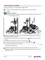
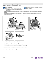
Sonden so installieren, dass das Alarmniveau über dem obersten Einschaltniveau
liegt.
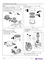
Blinddeckel inklusive Halterung abschrauben und wegnehmen . Dichtung und
Schrauben behalten.
Optischen Alarmgeber einhängen und mit den drei Schrauben fixieren .
Anschlusskabel durch Kabelschacht führen .
Im Schaltgerät im Menü |3.5 Sensorkonfiguration|
|3.5.1 Drucksensor + Optische Sonde | entsprechend anpassen.
Auf korrekten Sitz der Dichtung zwischen Zubehör und Grundkörper achten.
Funktionsprüfung gemäß der Einbau- und Wartungsanleitung der Anlage durchfüh-
ren.
016-337 2023/10

Optical alarm generator (art. no. 22205)
Suitable for Ecolift L art. no. 22002, 22003, 22006, 22007
Accessory is not suitable if a level sensor is already installed.
NOTICE
Disconnect system from energy sources!
Ensure that the electrical equipment is disconnected from the power supply
during the work.
1
2
3
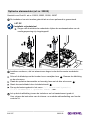
Install the probes so that the alarm level is above the top switching on level.
Unscrew and remove the blind plug including the bracket . Keep the seal and
screws.
Hook the optical alarm generator in place and fix it with the three screws .
Route the connection cable through the cable duct .
Adjust accordingly in the |3.5 Sensor configuration|
|3.5. 1 Pressure sensor + optical probe | menu of the control unit.
Make sure that the seal between the accessories and the drain body fits properly.
Carry out the functional test as described in the system’s installation and mainte-
nance instructions.
016-337 2023/10

Alarme optique (réf. 22205)
Convient pour Ecolift L réf. 22002, 22003, 22006, 22007
Cet accessoire n’est pas adapté si une sonde de niveau est déjà montée.
AVIS
Activer le système !
S'assurer que les appareils électriques sont coupés de l'alimentation en ten-
sion pendant les travaux.
1
2
3
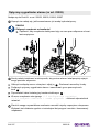
Installer les sondes de manière à ce que le niveau d’alarme se situe au-dessus du
niveau d'activation le plus haut.
Dévisser le bouchon ainsi que le support et les retirer . Mettre de côté le joint et
les vis.
Suspendre l’alarme optique et la fixer avec les trois vis .
Faire passer le câble de raccordement via le fourreau pour câbles .
Au niveau du gestionnaire, dans le menu |3.5 Configuration de capteurs|
|le point du menu 3.5.1 Capteur de pression + sonde optique | doit
être adapté en conséquence.
Veillez au bon positionnement du joint entre l'accessoire et le corps de base.
Effectuer un contrôle du fonctionnement suivant les instructions de pose et de main-
tenance du poste.
016-337 2023/10

Dispositivo di allarme ottico (cod.art. 22205)
Adatto a Ecolift L cod.art. 22002, 22003, 22006, 22007
L’accessorio non è adatto se è già installata una sonda idrostatica.
AVVISO
Mettere fuori tensione l’impianto!
Accertare che gli apparecchi elettrici siano separati dall’alimentazione di
tensione durante i lavori.
1
2
3
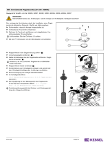
Installare la sonda in modo che il livello d’allarme si trovi al di sopra del livello di
accensione più alto.
Svitare e togliere il tappo cieco comprensivo del supporto . Conservare la guarni-
zione e le viti.
Agganciare il dispositivo di allarme ottico e fissarlo con le tre viti .
Posare il cavo di collegamento attraverso il pozzo per cavi .
Nella centralina, effettuare gli adeguamenti necessari
nel menu |3.5 Configurazione dei sensori|
|3.5.1 Sensore di pressione + sonda ottica | .
Prestare attenzione alla sede corretta della guarnizione tra accessorio e corpo base.
Eseguire la prova di funzionamento sulla base delle istruzioni per l’installazione e la
manutenzione dell’impianto.
016-337 2023/10

Optische alarmmelder (art.nr. 22205)
Geschikt voor Ecolift L art.nr. 22002, 22003, 22006, 22007
De toebehoor kan niet worden gebruikt als er al een peilsonde is gemonteerd.
LET OP
Installatie vrijschakelen!
Zorgen dat de elektrische onderdelen tijdens de werkzaamheden van de
voedingsspanning zijn losgekoppeld.
1
2
3
Installeer sondes zo, dat het alarmniveau hoger is dan het bovenste inschakelni-
veau.
Schroef de blindstop met de houder los en verwijder hem . Bewaar de afdichting
en de schroeven.
Plaats de optische alarmmelder en bevestig hem met de drie schroeven .
Steek de aansluitkabel door de kabelschacht .
Pas op de besturingskast in het menu |3.5 Sensorconfiguratie|
|3.5.1 Druksensor + optische sonde | aan.
Let op dat de afdichting tussen de toebehoor en het basiselement goed zit.
Voer volgens de instructies van de inbouw- en onderhoudshandleiding een functie-
controle uit.
016-337 2023/10

Optyczny sygnalizator alarmu (nr art. 22205)
Nadaje się do Ecolift L nr art. 22002, 22003, 22006, 22007
Osprzęt nie nadaje się, jeśli zamontowano już sondę hydrostatyczną.
UWAGA
Odłączyć urządzenie od zasilania!
Zapewnić, aby urządzenia elektryczne były na czas prac odłączone od zasi-
lania napięciem.
1
2
3
Sondy należy instalować w taki sposób, aby poziom alarmu leżał powyżej najwyż-
szego poziomu włączenia.
Odkręcić zaślepkę wraz z uchwytem i zdjąć ją . Zachować uszczelkę i śruby.
Podłączyć optyczny sygnalizator alarmu i zamocować go za pomocą trzech
śrub .
Poprowadzić kabel instalacyjny kanałem kablowym .
W menu urządzenia sterującego |3.5 Konfiguracja czujnika|
|3.5.1 Czujnik ciśnienia + sonda optyczna | dokonać odpowiednich
ustawień.
Zwrócić uwagę na prawidłowe osadzenie uszczelki między osprzętem a korpusem.
Wykonać test działania zgodnie z instrukcjami dotyczącymi montażu i konserwacji
urządzenia.
016-337 2023/10
-
 1
1
-
 2
2
-
 3
3
-
 4
4
-
 5
5
-
 6
6


Kessel 016-337 Beiblatt Optischer Alarmgeber Installation and Operating Instructions
- Typ
- Installation and Operating Instructions
w innych językach
Powiązane artykuły
-
 Kessel 016-335 Beiblatt Umrustset Pegelsonde - Ecolift L Installation and Operating Instructions
-
 Kessel 016-333 Beiblatt Umrüstsatz für zweite Pumpe Installation and Operating Instructions
-
 Kessel 016-334 Beiblatt Aktivkohlefilter DN 70 Installation and Operating Instructions
-
 Kessel 016-328 SG Ecolift L 230 V Installation and Operating Instructions
-
 Kessel 016-307 Minilift S Überflur Installation and Operating Instructions
-
 Kessel 010-701 Technikschacht-LW1000 Installation and Operating Instructions
-
 Kessel SG 400 V Mono Original Operation Manual
-
 Kessel SPZ 1000 Instrukcja obsługi


