
Universal dimmer switch
EUD12NPN-UC
GB
Temperature at mounting location:
-20°C up to +50°C.
Storage temperature: -25°C up to +70°C.
Relative humidity:
annual average value <75%.
21 100 806 - 4
Only skilled electricians may install this
electrical equipment otherwise there is
the risk of re or electric shock!
Universal dimmer switch. Power MOSFET
up to 400 W. Automatic lamp detection.
Standby loss 0.1 watt only. With adjustable
minimum or maximum brightness and
dimming speed. With switching operation
for children‘s rooms and snooze function.
Modular device for DIN EN 60715 TH35 rail
mounting. 1 module = 18 mm wide, 58 mm deep.
Universal dimmer switch for lamps up to
400 watts, depending on ventilation conditions.
Dimmable energy saving lamps ESL and
dimmable 230 V LED lamps dependent on
the lamps electronics and the dimming
technology.
Zero passage switching with soft start
and soft OFF to protect lamps.
Universal control voltage input 8 to 230 V UC,
electrically isolated from the 230 V supply
voltage and switching voltage. No minimum
load required.
Short-time control commands switch on/off,
permanent control varies the brightness to
the maximum level. An interruption of control
changes the direction of dimming.
The setting of the brightness level is stored
after switching off.
In case of a power failure the switching
position and the brightness level are stored.
If applicable the dimmer will be switched on
at the stored brightness level after the supply
voltage is recovered.
Glow lamp current up to 5 mA starting at 110 V.
Automatic electronic overload protection
and over-temperature switch-off.
Function rotary switch
The LED below the rotary switch on the front
shows control commands. It starts blinking
after 15 seconds if a pushbutton is inhibited.
In operation, the upper rotary switch de-
termines, whether automatic lamp detection
or special comfort positions should operate:
AUTO allows the dimming of all lamp types.
EC1 is a comfort position for energy saving
lamps which must be switched on with in-
creased power dependent on the construction,
so they will also switch on again safely in
cold condition when dimmed down.
EC2 is a comfort position for energy saving
lamps which will not be switched on again
when dimmed down dependent on the con-
struction. Memory is switched off in this
position.
LC1 is a comfort position for dimmable 230 V
LED lamps which are not being dimmed down
enough when set to AUTO (trailing phase
angle) dependent on the construction and
must therefore be forced to leading phase
angle.
LC2 and LC3 are comfort positions for dim-
mable 230 V LED lamps like LC1, but with
different dimming curves.
In positions EC1, EC2, LC1, LC2 and LC3 no
inductive (wound) transformers should be
used. In addition, the maximum number of
dimmable LED lamps can be lower than in the
AUTO position dependent on the construction.
The minimum brightness level (completely
dimmed down) or the maximum brightness
level (completely dimmed up) is adjustable
with the middle % rotary switch.
The dimming speed can be adjusted with
the lower dimming speed rotary switch.
The duration of soft start and soft OFF is
changed simultaneously.
With special switching operation for chil-
dren‘s rooms: If the light is switched on by
holding down the pushbutton, it starts at
the lowest brightness level after approx.
1 second and dims up slowly as long as the
pushbutton is held down without modifying
the last stored brightness level.
Snooze function: With a double impulse the
lighting is dimmed down from the current
dimming position to the minimum brightness
level and switched off. The current dimming
position as well as the adjustable minimum
brightness level determine the dimming time
(max. = 60 minutes) which can be reduced
as required. It can be switched off at any time
by short-time control commands during the
lighting is dimmed down. Holding down the
pushbutton during the dimming down pro-
cess dims up and stops the snooze function.
Mixing of L loads (inductive loads, e.g. wound
transformers) and C loads (capacitive loads,
e.g. electronic transformers) is not permitted.
R loads (ohmic loads, e.g. 230 V incandescent
lamps and halogen lamps) may be added
anytime.
The universal dimmer switch EUD12D in
conjunction with the capacity enhancer
LUD12 is suitable for mixing of L-loads and
C-loads.
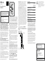
Typical connection
Technical data
Dimmable Trailing edge
230 V LED lamps up to 400 W 5)6)
Leading edge
up to 100 W 5)6)
Incandescent and up to 400 W 6)
halogen lamps 1) 230 V (R)
Inductive up to 400 W 2)3)6)
transformers (L)
Electronic up to 400 W 2)3)6)
transformers (C)
Dimmable energy saving up to 400 W 5)6)
lamps ESL
Max./min. temperature +50°C/-20°C 4)
at mounting location
Standby loss (activ power) 0.1 W
1) Applies to lamps of max. 150 W.
2) Per dimmer it is only allowed to use max. 2 inductive
(wound) transformers of the same type, furthermore
no-load operation on the secondary part is not
permitted. The dimmer might be destroyed. There-
fore do not permit load breaking on the secondary
part. Operation in parallel of inductive (wound) and
capacative (electronic) transformers is not permitted!
3)
When calculating the load a loss of 20% for inductive
(wound) transformers and a loss of 5% for capacitive
(electronic) transformers must be considered in
addition to the lamp load.
4) Affects the max. switching capacity.
5) Usually applies for dimmable energy saving lamps
and dimmable 230 V LED lamps. Due to differences in
the lamps electronics, there may be limited dimming
range, switch on and off problems dependent on the
manufacturer and a restriction on the maximum
number of lamps; especially if the connected load is
very low (for 5 W-LEDs). The comfort positions EC1,
EC2, LC1, LC2 and LC3 optimize the dimming range,
which, however, only gives a maximum power up to
100 W. No inductive (wound) transformers may be
dimmed in these comfort positions.
6) At a load of more than 200 W ventilation clearance of
½ module to adjacent devices must be maintained.
Must be kept for later use!
We recommend the housing for
operating instructions GBA14.
Eltako GmbH
D-70736 Fellbach
Technical Support English:
+49 711 94350025
technical-support@eltako.de
eltako.com
40/2021 Subject to change without notice.
The strain relief clamps of the
terminals must be closed, that
means the screws must be
tightened for testing the function
of the device. The terminals are
open ex works.
!
-
 1
1
