
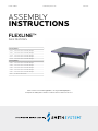
ASSEMBLY
INSTRUCTIONS
24" deep models
01373 Flex Station w/ Tilt Down Wire Manager
01374 Flex Station w/ Tilt Down Wire Manager
01376 Flex Station w/ Tilt Down Wire Manager
01377 Flex Station w/ Tilt Down Wire Manager
01378 Flex Station w/ Tilt Down Wire Manager
30" deep models
01383 Flex Station w/ Tilt Down Wire Manager
01384 Flex Station w/ Tilt Down Wire Manager
01385 Flex Station w/ Tilt Down Wire Manager
01386 Flex Station w/ Tilt Down Wire Manager
01387 Flex Station w/ Tilt Down Wire Manager
17221 Tie Plate for Flex Station
For assistance in assembling product, missing or damaged parts,
or to place an order, please contact Customer Service at 800-328-1061.
Form# 179844 www.smithsystem.com 08.17.2015
FLEXLINE™
FLEX STATIONS

For Assistance in assembling product, missing or damaged parts,
or to place an order, please contact customer service at 800-328-1061
You may also place your order online at
www.smithsystem.com
Form# 179844 01/2013
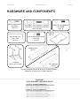
Hardware and Components
*For Models smaller than 60” wide use (2) 77549 (L-Brackets)
Models 60” or larger use (3) 77549 (L-Brackets)
Replacement Hardware Packs:
1. 69723-R – Flex Table Addional Hardware Pack
a. (11) 70054 – SM Screw #10x.75 HI/LO PTH
b. (3) 70088 – Screw, Buon Head 8MX20MM
2. 69729-R – Flex Y-Leg Hardware Pack
a. (4) 70870 – Connector Bolt ¼-20x23mm Nylok
b. (4) 70871 – Connector Nut ¼-20x17mm
c. (2) 77813 – Allen wrench 3/16” Short Arm
d. (17) 70054 – SM Screw #10x.75 HI.LO PTH
#10x3/4” Wood Screw
P/N: 70054
(QTY: 32)
P/N: 70867 – Connector Bolt ¼-20x23mm
P/N 70871 – Connector Nut ¼-20x17mm
(QTY: 8 of each)
Buon Hd Scrw M8x20mm
P/N: 70088
(QTY: 3)
Allen Wrench 3/16”
P/N: 77813
(QTY: 4)
3/8”-16x.625 Dog Nut Screw
P/N: 77741
(QTY: 8)
Table Top
(QTY: 1)
Y- Leg Sets
(QTY: 1 set of 2 Legs)
Modesty Panel
(QTY: 1)
Wire Manager
(QTY: 1)
[ 1 ] 69723-R FLEX TABLE HARDWARE PACK
QTY 11 #70054 - SM SCREW #10 X .75 HI/LO PTH
QTY 3 #70088 - SCREW, BUTTON HEAD 8M X 20MM
[ 2 ] 69729-R FLEX Y-LEG HARDWARE PACK
QTY 4 #70870 - CONNECTOR BOLT .25 - 20X23MM NYLOK
QTY 4 #70871 - CONNECTOR NUT .25 - 20X17MM
QTY 2 #77813 - ALLEN WRENCH (3/16”) SHORT ARM
QTY 17 #70054 - SM SCREW #10 X .75 HI/LO PTH
FLEXLINE™
REPLACEMENT HARDWARE PACKS
HARDWARE AND COMPONENTS
Form# 179844 www.smithsystem.com 08.17.2015

For Assistance in assembling product, missing or damaged parts,
or to place an order, please contact customer service at 800-328-1061
You may also place your order online at
www.smithsystem.com
Form# 179844 01/2013
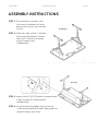
Assembly Instructions
Step 1: Place the top on a smooth, clean surface with the bottom facing up, being careful not to scratch
the top surface.
Step 2: Align the Y-legs and the “L” brackets with the Predrilled holes, but only attach the “L” brackets to
the top using (4) Wood Screws. (See Picture #1)
Step 3: Loosely attach the Panel to the Y-Legs using the (4) Connector Bolts (See Picture #2). ONLY HAND
TIGHTEN THE BOLTS.
Step 4: Using the remaining wood screws, attach the Y-Legs and the panel to the top. Go back and
tighten the bolts from Step 3.
Drawing 1
Drawing 2
STEP 1: Place the top on a smooth, clean
surface with the bottom facing up,
being careful not to scratch the top
surface.
STEP 2: Align the Y-legs and the “L” brackets
with the pre-drilled holes, but only
attach the “L” brackets to the top
using (4) wood screws.
(See drawing 1).
For Assistance in assembling product, missing or damaged parts,
or to place an order, please contact customer service at 800-328-1061
You may also place your order online at
www.smithsystem.com
Form# 179844 01/2013
Assembly Instructions
Step 1: Place the top on a smooth, clean surface with the bottom facing up, being careful not to scratch
the top surface.
Step 2: Align the Y-legs and the “L” brackets with the Predrilled holes, but only attach the “L” brackets to
the top using (4) Wood Screws. (See Picture #1)
Step 3: Loosely attach the Panel to the Y-Legs using the (4) Connector Bolts (See Picture #2). ONLY HAND
TIGHTEN THE BOLTS.
Step 4: Using the remaining wood screws, attach the Y-Legs and the panel to the top. Go back and
tighten the bolts from Step 3.
Drawing 1
Drawing 2
STEP 3: Loosely (HAND TIGHTEN) attach the panel to the
Y-legs using the (4) connector bolts.
(see drawing 2).
STEP 4: Using the remaining wood screws, attach the
Y-legs and the panel to the top. Go back and fully
tighten the bolts from Step 3.
ASSEMBLY INSTRUCTIONS
Form# 179844 www.smithsystem.com 08.17.2015

For Assistance in assembling product, missing or damaged parts,
or to place an order, please contact customer service at 800-328-1061
You may also place your order online at
www.smithsystem.com
Form# 179844 01/2013
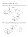
Step 5: Place the wire manager into the hooks located at the back of the panel. Using the (2) Button
Head Screws, attach the wire manager to the “L” Brackets (See Drawing 3).
Step 6: Adjust the legs to the desired height by loosening the 3/8”-16 Dog Nut Screws and pulling out
the lower part of the leg to the desired height (See Drawing 4). Use the Allen wrench provided to loosen
screws.
Drawing 3
For Assistance in assembling product, missing or damaged parts,
or to place an order, please contact customer service at 800-328-1061
You may also place your order online at
www.smithsystem.com
Form# 179844 01/2013
Step 5: Place the wire manager into the hooks located at the back of the panel. Using the (2) Button
Head Screws, attach the wire manager to the “L” Brackets (See Drawing 3).
Step 6: Adjust the legs to the desired height by loosening the 3/8”-16 Dog Nut Screws and pulling out
the lower part of the leg to the desired height (See Drawing 4). Use the Allen wrench provided to loosen
screws.
Drawing 3
STEP 6: Adjust the legs to the desired height by loosening the 3/8”-16 Dog Nut Screws and pulling
out the lower part of the leg to the desired height (see drawing 4). Use the Allen wrench
provided to loosen screws.
STEP 5: Place the wire manager into the hooks located at the back of the panel. Using the (2) button
head screws, attach the wire manager using the “L” Brackets (see drawing 3).
ASSEMBLY INSTRUCTIONS
Form# 179844 www.smithsystem.com 08.17.2015
-
 1
1
-
 2
2
-
 3
3
-
 4
4


w innych językach
- English: SMITH SYSTEM 179844
Inne dokumenty
-
ROOMS TO GO 10703812 Assembly Instructions
-
Follett Symphony C50HR400W-S Instrukcja obsługi
-
Follett Symphony 50CT400A/W Installation, Operation & Service Manual
-
Merrithew Health & Fitness Stability Chair Instrukcja obsługi
-
Sea Ray 2000 310 SUNDANCER Parts Manual
-
Spokey JONI Instrukcja obsługi
-
-
Matrix Rower Instrukcja obsługi
-
Yamaha S12 Instrukcja obsługi
-
Lincoln Electric IDEALARC SP-200 Instrukcja obsługi