Recommended weekly cleaning
1. Wash drain pan and grille with Solution A above. Rinse thoroughly.
2. Slowly pour solution of 237ml (8 oz) household bleach mixed with 3.8L (1gal) hot water into drain pan to help
prevent algae growth in drain lines.
If dispenser is a SensorSAFE unit:
3. Deactivate dispenser by depressing and releasing clean switch located on left side of unit under top front cover.
4. Clean lens using soft cloth and mild, non-abrasive cleaner.
5. Reactivate dispenser by depressing and releasing clean switch a second time (dispenser automatically
reactivates after two minutes).
Recommended quarterly cleaning of dispenser hopper
Note: If icemaker and dispenser are cleaned and sanitized at the same time, icemaker should be completed first.
1. Remove ice from dispenser.
2. Working inside storage area, remove center thumbscrew from dispense wheel, tilt wheel up toward back to clear
baffle and lift wheel out.
3. Remove front cover, chute cover and clear plastic chute.
4. Wipe lid, wheel, baffle, inside of storage area and clear plastic chute with damp cloth wrung out in Solution A.
5. Rinse all above items with damp cloth rinsed and wrung out in clear water.
6. Wipe all bin surfaces with Solution A.
7. Rinse thoroughly with clear, potable water.
8. Wipe with Solution B to sanitize.
9. Reinstall dispense wheel and other components.
If dispenser is equipped with chilled water accessory:
1. Remove four screws securing splash panel.
2. Disconnect 19mm (3/4") drain line from bottom of chilled water canister.
3. Loosen (do not remove) screw securing front bracket of chilled water canister to bottom of dispenser hopper.
4. Rotate canister clockwise to release front bracket, then pull canister forward to disengage rear bracket.
5. Remove chilled water coil from canister and clean with cloth wrung out in Solution A.
6. Wipe inside of chilled water canister with cloth wrung out in Solution A.
7. Rinse all above items with damp cloth wrung out in clear water.
8. Sanitize all above items with damp cloth wrung out in Solution B. Do not rinse.
9. Reinstall chilled water coil into canister (rubber alignment grommet on coil tubing must be located outside
chilled water canister to hold coil securely against canister wall).
10. Reinstall chilled water assembly on dispenser and tighten screw securing front bracket.
11. Reconnect 19mm (3/4") drain line to chilled water canister.
12. Reinstall splash panel and top front cover.
13. Restore power and test operation.
17
Quarterly cleaning of icemaker system
Units with icemakers require icemaker cleaning at least every 3 months, and more often if local water
conditions dictate. Failure to clean icemaker will result in decreased performance and potential damage
to icemaker. Refer to Icemaker Operation and Service Manual for specific cleaning instructions.
To avoid possible damage to motor assembly, use a damp cloth only. Do not allow water to run
through center hole in bottom of bin area.
!


 Highgrade HG-L4030 Karta katalogowa
 Native Trails DR340-SC Instrukcja instalacji
 Air Techniques Air/Water Separator Instrukcja obsługi
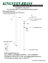 Kingston Brass HCC3162 Instrukcja instalacji