
Generator
Installation Manual. . . . . . . . . . . . . . 11
Generator
Montageanleitung . . . . . . . . . . . . . . 25
Générateur
Instructions de montage . . . . . . . . . 39
Generador
Instrucciones de montaje. . . . . . . . . 52
Generatore
Indicazioni di montaggio . . . . . . . . . 65
Generator
Montagehandleiding . . . . . . . . . . . . 79
Generator
Monteringsvejledning. . . . . . . . . . . . 93
Generator
Monteringsanvisning . . . . . . . . . . . 106
Generator
Monteringsanvisning . . . . . . . . . . . 119
Generaattori
Asennusohje . . . . . . . . . . . . . . . . . 132
Gerador
Instruções de montagem . . . . . . . . 145
Генератор
Инструкция по монтажу . . . . . . . . 158
Generator
Instrukcja montażu. . . . . . . . . . . . . 172
EN
DE
FR
ES
IT
NL
DA
SV
NO
FI
PT
RU
PL
Generàtor
Návod k montáži . . . . . . . . . . . . . . 185
Generàtor
Návod na montáž . . . . . . . . . . . . . 198
Generátor
Szerelési útmutató . . . . . . . . . . . . .211
CS
SK
HU
Dometic
TEC40D


TEC40D
3
2
4
3
1
1
765
467
490
2

TEC40D
4
490
770
3
4
5
6

TEC40D
5
Ø > 160 mm
1
2
3
4
7
max. 3 m
max. 1 m
8

TEC40D
6
3
1
2
9
Ø30
20
7,5
38
76
10510,5
126
0

TEC40D
7
230V 12V230V
0.pdf
1
43
2
a

TEC40D
8
6
5
4
3
2
1
6
5
4
3
2
1
1
2
6
5
4
3
2
1
6
5
4
3
2
1
12
987
654
321
4
5
5
6
1
2
3
4
9
12
13456
2
1
1
3
6
4
1
2
3
4
3596481
5
4
3
5
6
21
2
3
4
5
6
7
8
9
10
1
10
1
2
3
4
7
8
9
12
11
987
654
321
-
+
P
M
12
3
2
vt
pk
rt
gr
ws
bl
gn
br
ge
sw
vt
pk
rt
gr
ws
bl
gn
br
ge
sw
rt
rt
ws
ws
ws
rt
rt
rt
rt
sw
gr
sw
bl
bl
or
sw
or
ge
ws
vt
or
rt
sw
rt
sw
gr
sw
or
ws
ge
sw
or
rt
or
vt
21
1310815
5
5
9
27
24
4
17
14
22
28
18 26
25
12
16
23
11
7
20
19
6
1
2
3
b

TEC40D
9
bl br cy ge gn gr
DE Blau Braun Cyan Gelb Grün Grau
EN Blue Brown Cyan Yellow Green Grey
FR Bleu Marron Cyan Jaune Vert Gris
ES Azul Marrón Cian Amarillo Verde Gris
IT Blu Marrone Cyan Giallo Verde Grigio
NL Blauw Bruin Cyaan Geel Groen Grijs
DA Blå Brun Cyan Gul Grøn Grå
SV Blå Brun Cyan Gul Grön Grå
NO Blå Brun Cyan Gul Grønn Grå
FI Sininen Ruskea Syaani Keltainen Vihreä Harmaa
PT Azul Castanho Ciano Amarelo Verde Cinzento
RU Синий Коричневый Голубой Желтый Зеленый Серый
PL Niebieski Brązowy Cyjan Żółty Zielony Szary
CS Modrá Hněda Azurová Žlutá Zelená Šedá
SK Modrá Hnedá Azúrová Žltá Zelená Sivá
HU Kék Barna Cián Sárga Zöld Szürke
or pk rt sw vt ws
DE Orange Pink Rot Schwarz Violett Weiß
EN Orange Pink Red Black Violet White
FR Orange Rosa Rouge Noir Violeta Blanc
ES Naranja Rose Rojo Negro Lila Blanco
IT Arancione Rosa Rosso Nero Violetto Bianco
NL Oranje Roze Rood Zwart Paars Wit
DA Orange Lyserøde Rød Sort Violet Hvid
SV Orange Rosa Röd Svart Violett Vit
NO Oransje Rosa Rød Svart Fiolett Hvit
FI Oranssi Pinkki Punainen Musta Violetti Valkoinen
PT Cor de laranja Cor de rosa Vermelho Preto Violeta Branco
RU Оранжевый Розовый Красный Черный Фиолетовый Белый
PL Pomarańczowy Różowy Czerwony Czarny Fioletowy Biały
CS Oranžová Růžová Červená Černá Fialová Bílá
SK Oranžová Ružová Červená Čierna Fialová Biela
HU Narancs Rózsaszín Piros Fekete Ibolya Fehér

TEC40D
10
2
1
R2
3R3R1
4
A2
A1
R4
230 V
230 V
12 V
230 V / 1~
AG 113
+12 V
rt
1
2
3
4
c

EN
TEC40D
11
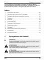
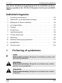
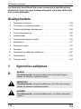
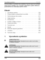
Please read this instruction manual carefully before installation and
first use, and store it in a safe place. If you pass on the product to
another person, hand over this instruction manual along with it.
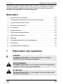
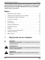
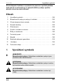
Table of contents
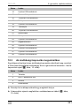
1 Explanation of symbols . . . . . . . . . . . . . . . . . . . . . . . . . . . . . . . . . . 12
2 Safety and installation instructions. . . . . . . . . . . . . . . . . . . . . . . . . . 13
3 Target group for this manual . . . . . . . . . . . . . . . . . . . . . . . . . . . . . . 15
4 Scope of delivery . . . . . . . . . . . . . . . . . . . . . . . . . . . . . . . . . . . . . . . 15
5 Accessories . . . . . . . . . . . . . . . . . . . . . . . . . . . . . . . . . . . . . . . . . . . 15
6 Intended use . . . . . . . . . . . . . . . . . . . . . . . . . . . . . . . . . . . . . . . . . . 16
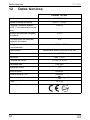
7 Labels . . . . . . . . . . . . . . . . . . . . . . . . . . . . . . . . . . . . . . . . . . . . . . . 16
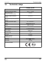
8 Technical description . . . . . . . . . . . . . . . . . . . . . . . . . . . . . . . . . . . . 16
9 Installation . . . . . . . . . . . . . . . . . . . . . . . . . . . . . . . . . . . . . . . . . . . . 17
10 Connecting the electrical power to the generator . . . . . . . . . . . . . . 19
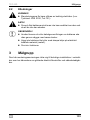
11 Disposal . . . . . . . . . . . . . . . . . . . . . . . . . . . . . . . . . . . . . . . . . . . . . . 23
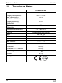
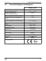
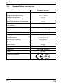
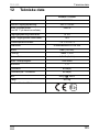
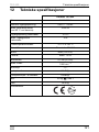
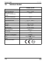
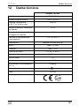
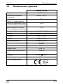
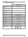
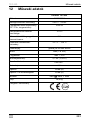
12 Technical data . . . . . . . . . . . . . . . . . . . . . . . . . . . . . . . . . . . . . . . . . 24

EN
Explanation of symbols TEC40D
12
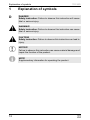
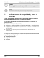
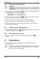
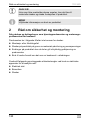
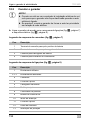
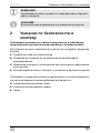
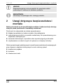
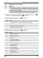
1 Explanation of symbols
D
!
!
A
I
DANGER!
Safety instruction: Failure to observe this instruction will cause
fatal or serious injury.
WARNING!
Safety instruction: Failure to observe this instruction can cause
fatal or serious injury.
CAUTION!
Safety instruction: Failure to observe this instruction can lead to
injury.
NOTICE!
Failure to observe this instruction can cause material damage and
impair the function of the product.
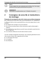
NOTE
Supplementary information for operating the product.

EN
TEC40D Safety and installation instructions
13
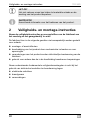
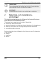
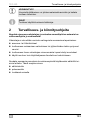
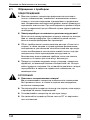
2 Safety and installation instructions
Please observe the prescribed safety instructions and stipulations
from the vehicle manufacturer and service workshops.
The manufacturer accepts no liability for damage in the following cases:
l Faulty assembly or connection
l Damage to the product resulting from mechanical influences and excess
voltage
l Alterations to the product without express permission from the manu-
facturer
l Use for purposes other than those described in the operating manual
Note the following basic safety information when using electrical devices to
protect against:
l Electric shock
l Fire hazards
lInjury
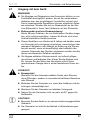
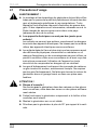
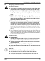
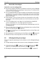
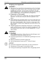
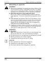
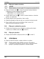
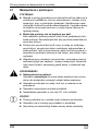
2.1 Using the device
!
WARNING!
Installing and repairing the device may only be carried out by
qualified personnel who are familiar with the risks involved and
the relevant regulations. Inadequate repairs may cause serious
hazards. For repair service, please contact the service centre in
your country (addresses on the back page).
Electrical devices are not toys
Keep electrical devices out of reach of children or infirm per-
sons. Do not allow them to use electrical devices without super-
vision.
This device can be used by children aged 8 years or over, as
well as by persons with diminished physical, sensory or mental
capacities or a lack of experience and/or knowledge, providing
they are supervised or have been taught how to use the device
safely and are aware of the resulting risks.

EN
Safety and installation instructions TEC40D
14
Exhaust fumes contain carbon monoxide which is a highly toxic,
odourless and colourless gas. Do not inhale any exhaust fumes.
Do not leave the generator motor running in a closed garage or
in a room without windows.
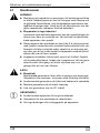
!
CAUTION!
Fire hazards
Do not install the generator in a box or room without any open-
ings, but in well-ventilated spaces instead.
Only operate the generator if you are certain that the housing
and the cables are undamaged.
Install the generator on a stable surface.
Do not tilt the generator more than 20° from the vertical position.
A
NOTICE!
Only use the device as intended.
The generator is not suitable for use in water vessels.
Do not make any alterations or conversions to the device.
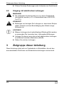
2.2 Handling electrical cables
!
WARNING!
The electrical power supply may only be connected by a quali-
fied electrician (e.g. according to VDE 0100, Part 721 in
Germany).
!
CAUTION!
Attach and lay the cables so that they cannot be tripped over or
damaged.
A
NOTICE!
Use cable ducts to lay cables through walls with sharp edges.
Do not lay loose or bent cables next to electrically conductive
materials (metal).
Do not pull on the cables.

EN
TEC40D Target group for this manual
15
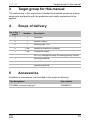
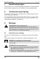
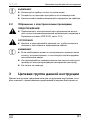
3 Target group for this manual
The instructions in this manual are intended for qualified personnel at work-
shops who are familiar with the guidelines and safety precautions to be
applied.
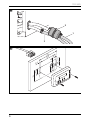
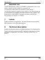
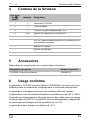
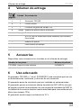
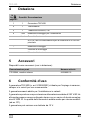
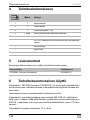
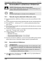
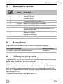
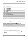
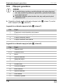
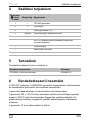
4 Scope of delivery
5 Accessories
Available as accessories (not included in the scope of delivery):
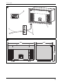
No. in fig. 1,
page 3
Number Description
1 1 Generator
2 1 Remote control
3 1 Exhaust pipe, 2 m
4 1 set Fastening material for silencer
– 1 set Connection cable
AG 102, changeover relay for making priority circuits
– Mounting material
Installation manual
Operating manual
Part designation Item number
PR 25044, external sealing kit 9102900174

EN
Intended use TEC40D
16
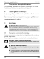
6 Intended use
The TEC40D generator (item no. 9102900201) is designed for use in motor
homes, camper vans and vehicles for commercial use.
The generator is not suitable for installation in water vessels.
The generator produces a pure sine wave voltage of 230 V/50 Hz which can
be connected to the consumer with a total continuous load of 3500 W. The
power quality is also suitable for sensitive consumers (such as PCs).
The generator can charge a 12 V battery.
7Labels
A label is attached to the generator. This label provides the user and fitter
with information on the device specifications.
8 Technical description
Installing the generator must be configured according to the following option:
Priority circuit which prioritises the 230 V external voltage over the voltage
produced by the generator, see chapter “Creating a priority circuit” on
page 22.

EN
TEC40D Installation
17
9 Installation
!
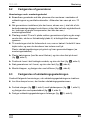
9.1 Note on installation
Read the installation manual carefully before you install the generator.
When installing the generator, note the following:
D
!
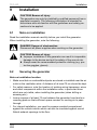
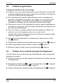
9.2 Securing the generator
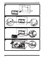
Note on installation location
l Make sure that no combustible objects are stored or installed near the air
outlet or the ventilation slots. A distance of at least 70 cm should be kept.
l For safety reasons, note the location of existing wiring harnesses, wires
and other components within the installation area, in particular those
which are not visible, when installing the generator (when drilling or
screwing etc.).
l Leave a space of at least 70 mm between the generator hood and sur-
rounding parts so that sufficient space remains for cooling air to pass
through.
l For internal installation, you need to prepare a sealed compartment
against the vehicle interior which can also be insulated against sound.
Attach exhaust openings to the floor.
CAUTION! Beware of injury
The generator may only be installed by qualified personnel from a
specialist company. The following information is intended for
technicians who are familiar with the guidelines and safety pre-
cautions to be applied.
DANGER! Danger of electrocution
Disconnect all power supplies when working on the generator.
CAUTION! Beware of injury
Improper installation of the generator can result in irreparable
damage to the device and put the safety of the user at risk.
Always wear the recommended protective clothing (e.g. pro-
tective goggles, gloves).

EN
Installation TEC40D
18
ä Mount the gaskets (available as accessory) to the casing and fix them
with the srews (fig. 3, page 4).
ä Position the casing in the desired area and attach it with the appropriate
screws (fig. 4, page 4).
ä Insert the engine plate into the casing and screw it into place (fig. 5,
page 4).
ä Mount the casing cover and attach it with the pins (fig. 6, page 4).
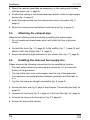
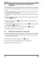
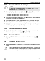
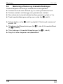
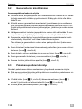
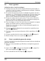
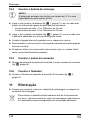
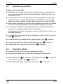
9.3 Attaching the exhaust pipe
Observe the following instructions when installing the exhaust pipe:
l Do not create any sharp bends which will inhibit the flow of exhaust
fumes.
ä Connect the hose (fig. 7 2, page 5) to the muffler (fig. 7 1, page 5) and
attach it with the clamps (fig. 7 4, page 5)
ä Secure the exhaust pipe extension to the vehicle floor (fig. 7 3, page 5).
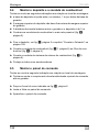
9.4 Installing the tank and fuel supply line
Please observe the following instructions for the installation location:
l The tank bottom must be positioned at a maximum of 1 m below the
bottom of the generator.
l The top of the tank must not be higher than the top of the generator.
l The maximum horizontal distance between generator and fuel tank is
3m.
l Lay the fuel hoses as straight as possible (fig. 8, page 5).
ä Secure the tank, see fig. 8, page 5 and chapter “Connecting the float” on
page 23.
ä Connect the fuel hose (fig. 9 1, page 6) to the fuel filter (fig. 9 2, page 6).
ä Connect the hose to the fuel return (fig. 9 3, page 6).
ä Secure the hoses with clamps.

EN
TEC40D Connecting the electrical power to the generator
19
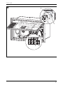
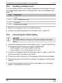
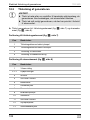
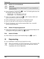
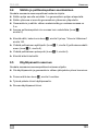
9.5 Mounting the control panel
Please observe the following instructions for the installation location:
l Observe the length of the extension cable from the control panel to the
generator.
ä Drill the holes as shown in fig. 0, page 6.
ä Insert the plug into the control panel.
ä Screw on the control panel.
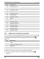
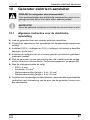
10 Connecting the electrical power to the
generator
D
I
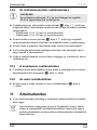
10.1 Important notes on the electrical connection
l Only a qualified electrician should connect the generator to the electrical
power.
l Check that the voltage specification on the type plate is the same as that
of the power supply.
l Do not lay the 230 Vw mains cable and the 12 Vg cable together in the
same cable duct.
l Do not lay cables which are loose or bent next to electrically conductive
material (metal).
l Connect the generator to a power circuit which can supply the necessary
current (see chapter “Technical data” on page 24).
l Select the cross-section of the cable as follows:
–230V: 4mm²
– Battery charger: 2.5 mm²
– Starter battery connection (length < 6 m): 16 mm²
– Starter battery connection (length > 6 m): 25 mm²
DANGER! Danger of electrocution
Make sure there is no voltage at electrically operated components
before carrying out work on them!
NOTE
Observe the applicable guidelines in the country of the consumer.

EN
Connecting the electrical power to the generator TEC40D
20
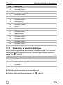
l Install a manual main switch which can disconnect all the consumers from
the generator with the exception of the battery.
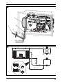
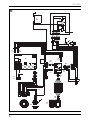
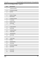
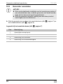
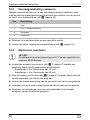
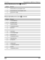
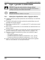
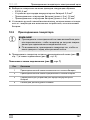
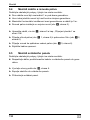
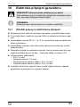
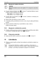
10.2 Connecting the generator
A
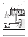
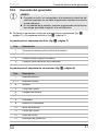
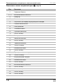
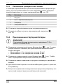
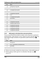
ä Connect the generator in accordance with the circuit diagrams (fig. a,
page 7) and (fig. b, page 8).
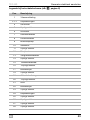
Key for circuit diagram (fig. a, page 7)
NOTICE!
Connect a relay or a switch to the vehicle’s electrical system
so that the generator is not damaged when the power supply
is switched on.
Connect the generator so that it takes priority over the power
supply.
Item Description
1 Battery positive terminal
2 Battery negative terminal
3 Battery charger connection
4 Fuel gauge connection
Strona się ładuje...
Strona się ładuje...
Strona się ładuje...
Strona się ładuje...
Strona się ładuje...
Strona się ładuje...
Strona się ładuje...
Strona się ładuje...
Strona się ładuje...
Strona się ładuje...
Strona się ładuje...
Strona się ładuje...
Strona się ładuje...
Strona się ładuje...
Strona się ładuje...
Strona się ładuje...
Strona się ładuje...
Strona się ładuje...
Strona się ładuje...
Strona się ładuje...
Strona się ładuje...
Strona się ładuje...
Strona się ładuje...
Strona się ładuje...
Strona się ładuje...
Strona się ładuje...
Strona się ładuje...
Strona się ładuje...
Strona się ładuje...
Strona się ładuje...
Strona się ładuje...
Strona się ładuje...
Strona się ładuje...
Strona się ładuje...
Strona się ładuje...
Strona się ładuje...
Strona się ładuje...
Strona się ładuje...
Strona się ładuje...
Strona się ładuje...
Strona się ładuje...
Strona się ładuje...
Strona się ładuje...
Strona się ładuje...
Strona się ładuje...
Strona się ładuje...
Strona się ładuje...
Strona się ładuje...
Strona się ładuje...
Strona się ładuje...
Strona się ładuje...
Strona się ładuje...
Strona się ładuje...
Strona się ładuje...
Strona się ładuje...
Strona się ładuje...
Strona się ładuje...
Strona się ładuje...
Strona się ładuje...
Strona się ładuje...
Strona się ładuje...
Strona się ładuje...
Strona się ładuje...
Strona się ładuje...
Strona się ładuje...
Strona się ładuje...
Strona się ładuje...
Strona się ładuje...
Strona się ładuje...
Strona się ładuje...
Strona się ładuje...
Strona się ładuje...
Strona się ładuje...
Strona się ładuje...
Strona się ładuje...
Strona się ładuje...
Strona się ładuje...
Strona się ładuje...
Strona się ładuje...
Strona się ładuje...
Strona się ładuje...
Strona się ładuje...
Strona się ładuje...
Strona się ładuje...
Strona się ładuje...
Strona się ładuje...
Strona się ładuje...
Strona się ładuje...
Strona się ładuje...
Strona się ładuje...
Strona się ładuje...
Strona się ładuje...
Strona się ładuje...
Strona się ładuje...
Strona się ładuje...
Strona się ładuje...
Strona się ładuje...
Strona się ładuje...
Strona się ładuje...
Strona się ładuje...
Strona się ładuje...
Strona się ładuje...
Strona się ładuje...
Strona się ładuje...
Strona się ładuje...
Strona się ładuje...
Strona się ładuje...
Strona się ładuje...
Strona się ładuje...
Strona się ładuje...
Strona się ładuje...
Strona się ładuje...
Strona się ładuje...
Strona się ładuje...
Strona się ładuje...
Strona się ładuje...
Strona się ładuje...
Strona się ładuje...
Strona się ładuje...
Strona się ładuje...
Strona się ładuje...
Strona się ładuje...
Strona się ładuje...
Strona się ładuje...
Strona się ładuje...
Strona się ładuje...
Strona się ładuje...
Strona się ładuje...
Strona się ładuje...
Strona się ładuje...
Strona się ładuje...
Strona się ładuje...
Strona się ładuje...
Strona się ładuje...
Strona się ładuje...
Strona się ładuje...
Strona się ładuje...
Strona się ładuje...
Strona się ładuje...
Strona się ładuje...
Strona się ładuje...
Strona się ładuje...
Strona się ładuje...
Strona się ładuje...
Strona się ładuje...
Strona się ładuje...
Strona się ładuje...
Strona się ładuje...
Strona się ładuje...
Strona się ładuje...
Strona się ładuje...
Strona się ładuje...
Strona się ładuje...
Strona się ładuje...
Strona się ładuje...
Strona się ładuje...
Strona się ładuje...
Strona się ładuje...
Strona się ładuje...
Strona się ładuje...
Strona się ładuje...
Strona się ładuje...
Strona się ładuje...
Strona się ładuje...
Strona się ładuje...
Strona się ładuje...
Strona się ładuje...
Strona się ładuje...
Strona się ładuje...
Strona się ładuje...
Strona się ładuje...
Strona się ładuje...
Strona się ładuje...
Strona się ładuje...
Strona się ładuje...
Strona się ładuje...
Strona się ładuje...
Strona się ładuje...
Strona się ładuje...
Strona się ładuje...
Strona się ładuje...
Strona się ładuje...
Strona się ładuje...
Strona się ładuje...
Strona się ładuje...
Strona się ładuje...
Strona się ładuje...
Strona się ładuje...
Strona się ładuje...
Strona się ładuje...
Strona się ładuje...
Strona się ładuje...
Strona się ładuje...
Strona się ładuje...
Strona się ładuje...
Strona się ładuje...
Strona się ładuje...
Strona się ładuje...
Strona się ładuje...
Strona się ładuje...
Strona się ładuje...
Strona się ładuje...
Strona się ładuje...
Strona się ładuje...
-
 1
1
-
 2
2
-
 3
3
-
 4
4
-
 5
5
-
 6
6
-
 7
7
-
 8
8
-
 9
9
-
 10
10
-
 11
11
-
 12
12
-
 13
13
-
 14
14
-
 15
15
-
 16
16
-
 17
17
-
 18
18
-
 19
19
-
 20
20
-
 21
21
-
 22
22
-
 23
23
-
 24
24
-
 25
25
-
 26
26
-
 27
27
-
 28
28
-
 29
29
-
 30
30
-
 31
31
-
 32
32
-
 33
33
-
 34
34
-
 35
35
-
 36
36
-
 37
37
-
 38
38
-
 39
39
-
 40
40
-
 41
41
-
 42
42
-
 43
43
-
 44
44
-
 45
45
-
 46
46
-
 47
47
-
 48
48
-
 49
49
-
 50
50
-
 51
51
-
 52
52
-
 53
53
-
 54
54
-
 55
55
-
 56
56
-
 57
57
-
 58
58
-
 59
59
-
 60
60
-
 61
61
-
 62
62
-
 63
63
-
 64
64
-
 65
65
-
 66
66
-
 67
67
-
 68
68
-
 69
69
-
 70
70
-
 71
71
-
 72
72
-
 73
73
-
 74
74
-
 75
75
-
 76
76
-
 77
77
-
 78
78
-
 79
79
-
 80
80
-
 81
81
-
 82
82
-
 83
83
-
 84
84
-
 85
85
-
 86
86
-
 87
87
-
 88
88
-
 89
89
-
 90
90
-
 91
91
-
 92
92
-
 93
93
-
 94
94
-
 95
95
-
 96
96
-
 97
97
-
 98
98
-
 99
99
-
 100
100
-
 101
101
-
 102
102
-
 103
103
-
 104
104
-
 105
105
-
 106
106
-
 107
107
-
 108
108
-
 109
109
-
 110
110
-
 111
111
-
 112
112
-
 113
113
-
 114
114
-
 115
115
-
 116
116
-
 117
117
-
 118
118
-
 119
119
-
 120
120
-
 121
121
-
 122
122
-
 123
123
-
 124
124
-
 125
125
-
 126
126
-
 127
127
-
 128
128
-
 129
129
-
 130
130
-
 131
131
-
 132
132
-
 133
133
-
 134
134
-
 135
135
-
 136
136
-
 137
137
-
 138
138
-
 139
139
-
 140
140
-
 141
141
-
 142
142
-
 143
143
-
 144
144
-
 145
145
-
 146
146
-
 147
147
-
 148
148
-
 149
149
-
 150
150
-
 151
151
-
 152
152
-
 153
153
-
 154
154
-
 155
155
-
 156
156
-
 157
157
-
 158
158
-
 159
159
-
 160
160
-
 161
161
-
 162
162
-
 163
163
-
 164
164
-
 165
165
-
 166
166
-
 167
167
-
 168
168
-
 169
169
-
 170
170
-
 171
171
-
 172
172
-
 173
173
-
 174
174
-
 175
175
-
 176
176
-
 177
177
-
 178
178
-
 179
179
-
 180
180
-
 181
181
-
 182
182
-
 183
183
-
 184
184
-
 185
185
-
 186
186
-
 187
187
-
 188
188
-
 189
189
-
 190
190
-
 191
191
-
 192
192
-
 193
193
-
 194
194
-
 195
195
-
 196
196
-
 197
197
-
 198
198
-
 199
199
-
 200
200
-
 201
201
-
 202
202
-
 203
203
-
 204
204
-
 205
205
-
 206
206
-
 207
207
-
 208
208
-
 209
209
-
 210
210
-
 211
211
-
 212
212
-
 213
213
-
 214
214
-
 215
215
-
 216
216
-
 217
217
-
 218
218
-
 219
219
-
 220
220
-
 221
221
-
 222
222
-
 223
223
-
 224
224


Dometic TEC 40D Operation Instrukcja instalacji
- Typ
- Instrukcja instalacji
- Niniejsza instrukcja jest również odpowiednia dla
w innych językach
- čeština: Dometic TEC 40D Operation instalační příručka
- español: Dometic TEC 40D Operation Guía de instalación
- italiano: Dometic TEC 40D Operation Guida d'installazione
- Deutsch: Dometic TEC 40D Operation Installationsanleitung
- slovenčina: Dometic TEC 40D Operation Návod na inštaláciu
- svenska: Dometic TEC 40D Operation Installationsguide
- português: Dometic TEC 40D Operation Guia de instalação
- français: Dometic TEC 40D Operation Guide d'installation
- English: Dometic TEC 40D Operation Installation guide
- dansk: Dometic TEC 40D Operation Installationsvejledning
- русский: Dometic TEC 40D Operation Инструкция по установке
- suomi: Dometic TEC 40D Operation Asennusohje
- Nederlands: Dometic TEC 40D Operation Installatie gids
Powiązane artykuły
-
Dometic TEC40D EV Instrukcja instalacji
-
-
-
-
-
-
-
-
-
