
-----
-----<
BOOK
NOB556
I
CIRCULAR
SAW
BENCH
PLEASE INSERT SERIAL
NUMBER OF MACHINE
MODIFICATIONS
ARE MADE
TO
THESE BOOKS FROM TIME
TO
TIME
AND IT IS IMPORTANT THEREFORE THAT
ONLY
THE BOOK SENT
WITH
THE MACHINE SHOULD
BE
USEDAS A WORKING MANUAL
www.DaltonsWadkin.com
www.DaltonsWadkin.com
www.DaltonsWadkin.com

------
_
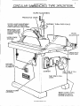
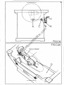
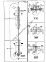
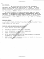
CIRCULAR
SAWBENCHES
TYPE
24'&26"BSW
RIVING KNIFE
~'"'--_-C_-:
'MCLt:
TO
SUIT SIZE
RISES
AND
FALLS
lAIn
...
MACHINE
REFERENCE
-.NUMBER
PLATE~
\SI.
......
~
-.
~~
......
CANTABLE TURN-OVER FENCE
MICRO
ADJUSTMENT
:[I~-1r-JCr:::~~::::~~GRADUATED
..
FENCE
BAR
STARTER
~\
SAW
RISE
& FALL
HANDWHEEl.
SAW
RISE
&
FALL
LOCK.
REAR
COVER
GIVES
ACCESS
TO
BELTS,
MOTOR
& PULLEYS.
www.DaltonsWadkin.com
www.DaltonsWadkin.com
www.DaltonsWadkin.com

2
-------
-------------------------------------
SECTION A
SECTION B
SECTION C
SEc'nON
D
SECTION E
SECTION A
S8CTION B
SECTION C
SECTION
D
. SECTIONS
SPECIFICATION
INSTALLATION
DESCRIPTION
&
OPERATION
MAINTENANCE
SPARE
PARTS
LIST
ILLUSTRATIONS
FIG
Al
FIG
Bl
FIG
B2
FIG
Cl
FIG
C2
FIG CJ
FIG
c4
FIG
C4A
FIG
CS
FIG
C6
FIG
C7
FIG
CS-Cll
FIG
Dl
FIG
D2-DJ
FIG
D4-D12
FIG
D1J
24/26'
BSW
CDWULAR
SAWHENCHES
WDUNG
DIAGRAH
(J
PHASE)
FOUNDATION
PLAN
CANTING
FENCE
CONTROLS
FENCE
ALIGNMENT
POINTS
RIVING KNH'E
DETAIL
RISE
AND
FALL
CONTROLS
RIVING KNIFE
DETAIL
"
MITRE
FENCE
MITRE
FI!;NCE
STOP
ROJ)
POSITIONS
!
SAW
PACKINGS
OPI!;RATION
OF
OPTIONAL
FEATURES
,!
SA\{
SPINDLI!;
ASSJ!:lolllLY
DI!;LT
TENSIONING
SAW
MAINTENANCE
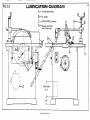
LUI.lIUCATION
,{
www.DaltonsWadkin.com
www.DaltonsWadkin.com
www.DaltonsWadkin.com

-,-
SPECIFICA
nON
i
Maximum
diameter
of
saw
_________________
_
Maximum saw projection
Size
of
table
Table
height
Max. distance saw to fence
Fence dimensions
Fence cants
up
to
Rise
and
fall
of
saw spindle
_________________
_
Speed
of
saw spindle
___________
~.
________
~
Horse power
of
motor
Diameter
of
saw
bore
optional
Diameter
of
driving
pin
Net
weight
Gross weight
Shipping
dimensions
.-._--
..
_----
24"
BSW
600
24/1
600mm.
9"
225mm.
43" x 34"
1090
x 860mm.
34"
865mm.
20"
500mm.
22/1
x 6"
560 x 150mm.
45"
5"
130mm.
1750 r.p.m.
7!
(optional
10)
1
&"
or
45mm.
l"
2
12mm.
1000 lb.
450 kg.
1290 lb.
590 kg.
52
eu. ft.
1.5
m'
:1
26"
BSW
650
26"
650mm.
10"
255mm.
43" x
34/1
1090 x 860mm.
34/1
865mm.
20"
500mm.
21"x
7r'
535
x 190mm.
45
5"
130mm.
1650
Lp.m.
10
If'
or
45111111.
~"
12mm.
1000 lb.
450 kg.
1290 lb.
590 kg.
52
eu. ft.
1.5 m
3
www.DaltonsWadkin.com
www.DaltonsWadkin.com
www.DaltonsWadkin.com

4
SECTION B
,
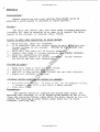
Installation:
-
I
Remove
protective
anti-rust
coating
from
bright
parts
by
'applyin~
a
cloth
soaked
in
paraffin
or
other
solvent.
Wiring:-
The
motor
and
control
gear
have
been
wired
in
before
despatch,
therefore
all
that
is
required
to
be
done
is
to
connect
the
mains
supply
to
the
starter,
or
isolator
where
fitted.
POINTS
TO
NOTE
lVHEN
CONNECTING
TO
POWER
SUPPLY.
~
-
Check
voltage,
phasA
and
frequency
2 -
It
is
important
that
the
correct
cable
is
used
to
delivAr
the
correct
voltage
to
the
starter.
RUNNING
ON
LOW
VOLTAGE
WILL
DANAGE
HOTOR.
3 -
Check
main
line
fuses
are
of
correct
capacity.
I, _
Connect
line
leads
to
correct
termin"ls
(SEE
WIRING DIAGRA}I).
5 -
Check
all
connections
are
sound.
6
Check
spindle
rotates
in
correct
direction.
If
not
reverse
any
two
of
the
line
lead
connections.
FAILURE
TO
START:-
I -
Fuses
have
blown
or
have
not
been
fitted.
2 -
Isolator
switch
ha9
not
been
closed.
J -
Lock
off
or
stop
button
(when
fitted)
has
not
been
released.
4 -
Supply
~ot
available
at
mAchl.ne.
SlOPPAGF; DUll
ING
OPBRATTON
&.
FA
lLUHE
TO
l'(ESTART:-
1 -
Ov',rloads
have
tripped.
If
i,and
re-set,
set
by
pressine:
hutton.
J f
automatJ.c
they
will
1'.'-S8L
after
a
short
period.
2.
-
FU:.ies
have
bJown.
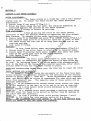
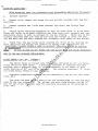
Foundation:-
The
machine
should
be
levelled'
and
bolted
down
firmly.
For
mounting
into
concrete,
6"
to
8"
square
holes
should
be
cut
in
the
floor
and
rag
bolts
fitted,
after
which
the
holes
"hould
be
run
with
cement.
For
mounting
on
wood
floors
cOBch
bolts
will
be
found
adequate.
(see
Fig.
B2.)
www.DaltonsWadkin.com
www.DaltonsWadkin.com
www.DaltonsWadkin.com

,--
-
-------------------
----
--------------------
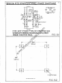
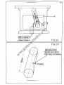
~ROOK
RT3
STARTERCTHREE
PHASE
DIAGRAM)
,
SUP,PlY
L1
l2
LINK'
X'
BROWN
I
LlNK'T'
_I
ORANGE
\ 5
13
).
3
ab
21
33
(11)6
(13~(j5)~
~
--U---O-
c
---0-
-----0
-{P
14
~
22
14)
START
(12) 2 4 '
,6
34(16)
LINK W
REMOTE
"START.STOP"
BUTTONS
9r)
____
34t~TAR~3r5)
~6o-l
Ol.
95,(7)
O~
\--lPSTOP/RESET
BROWN
2 4 6
98.
96
(8)
(9)
(Tl)
(r2)
n)
LlNK'ZI
A B C VIOLET
"-'--..:::...--,.~~
MOTOR
5
FOR
ANY
OTHER
TYPE
OF
STARTING
SEE
SEPARATE
WIRING
DIAGRAM
ENCLOSED
INSIDE
STARTER
BOX.
FIG
BI
~
23"
(S8Smm)
0(
--
I
26~'
~
..
(666
mm)
---
----
-
--
--------
~-
--
~
-----------+-I~t
5"
4 - 8 Dia holes
FIG
B2
www.DaltonsWadkin.com
www.DaltonsWadkin.com
www.DaltonsWadkin.com

6
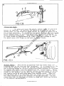
SECTION C
CANTING
&
RIP
FENCE
CONTROLS
.QUICK
ADJUSn!ENT:-
The
fence
slides
on
a
round
bar
with
a
rule
incorp-
orated
into
it.
To
adjust
the
fence
follow
the
under
mentioned
proceedure:-
1.
Unlock
lever
'A:
and
screw'B'(Fig.C.l.)
2.
Slide
the
fence
along
the
bar
until
the
required
dimension
is
indicated
against
the
pointer
on
the
fence
bracket.
J.
Lock
lever
'A!
firmly
to
secure
in
position.
FINE
ADJUSIMENII-
After
adjusting
the
fence
by
the
above
method
provision
is
made
for
precise
setting
by
operating
the
fine
adjust-
ment
feature.
To
operate
follow
under
mentioned
proceedure.
1.
Ensure
lever
'A'
is
UNLOCKED
and
screw'B'ia
LOCKED
firmly.(Fig.C.l.)
2.
Turn
knurled
hand
screw'C'in
direction
required
in
order
to
draw
the
fence
along
the
rule
bar
to
or
away
from
the
saw
and
to
the
required
setting.
J.
Lock
lever
'K
firmly.
CANTING:-
To
cant
fence
follow
under
mentioned
proceedure
(Fig.C.l.)
1.
Unlock
lever'D'and
allow
fence
to
pivot
over
to
required
angle.
2.
Unlock
lever'E'allowing
fence
plate
to
drop
down
until
the
lower
edge
of
the
plate
lies
flat
on
the
table
surface.
\'
",
J.
Lock
levers
D
and
E
firmly.
FENCE
POSITIONING:-
The
fence
plate
is
designed
to
slide
along
the
table
in
order
to
compensate
for
different
sizes
of
saws
which
may
be
used.
By
unlocking
lever
'E'
the
plate
maybe
s'lid
alongadovetail
slot
in
the
back
of
the
fence
to
the
required
position,
after
which
locking
lever'E'will
fix
the
fence
firmly
in
place.
NOTE:-For
crosscutting
swing
fence
over
the'
rule
bar
to
clear
the
table
FENCE SETTING
AND
ALIGNINGI-
On
despatch
from
the
works
the
movements
of
the
fence
have
been
finely
adjusted
for
accurate
cutting
by
the
provi,sion
of
the
setting
screws
at
points
F.G.H. I.
(FIG
C2).
These
adjustments
have
seperate
uses,
and
should
only
be
re-set
to
compensate
for
wear
which
may
take
place
from
constant
use.
The
seperate
uses
of
these
points
are
as
outlined
underneath:-
POINT
F&-
is
an
eccentrically
turned
centre
which
allows
the
fence
to
be
set
paralell
to
the
saw.
or
to
be
set
in
or
out
as
requ
tred.
POINT
G:-
is
s
true
centre
which
allows
slackness
to
be
removed
between
centres
F
and
G.
POINT H:-
is
a
jacking
point
which
provides
a
positive
stop
which
will
not
allow
the
fence
to
be
pulled
up
further
than
90
degrees
to
the
table
when
set
correctly.
POINT
1:-
is
also
a
jacking
point
which
brings
centres
F
and
G
parallel
to
the
table
for
true
canting
action
of
the
fence.
NOTE:-
SET
ALIGNMENT
ONLY
WITH
CENTRE
F.
DO
NOT
PACK
BETWEEN
BACK
PLATE
AND
FENCE
AS
TIllS
CAN
CRACK
THE
CASTINGS.
www.DaltonsWadkin.com
www.DaltonsWadkin.com
www.DaltonsWadkin.com

--
,
7
FIG.Cl
FIGC2
www.DaltonsWadkin.com
www.DaltonsWadkin.com
www.DaltonsWadkin.com

8
RISE
AND
FALL
CONTROLS:-
By
turning
handwheel
'J'
(fig.
C4
)
the
sa"
may
be
r~ised
or
lo"ered
between
the
maximum
and
m1.nimum
position
as
given
in
section
'A'
specification.
Under.
no
circumstances
should
this
dimension
be
varied.
It
is
important
after
operatin~
the
rise
and
fall
that
lever
handle
'K'
is
locked
firmly
before
running
the
saw.
The
rise
and
fall
handwheel
is
connected
through
pivoted
yolks
at
points
A.
&
B.
(FIG
C4.)
At
the
handwheel
end
of
the
screw
a
thrust
race
C
is
fitted
to
give
free
ro·tation
"hen
in
use.
It
is
therefore
important
that
the
pivots
and
screw
are
cleaned
and
luhricated
regular-
ly
and
that
the
thrust
race
is
oiled
accordinl"
to
the
maintenance
schedule.
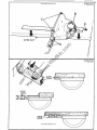
llIVING
KNIFE
PLATE:-
The
riving
knif"
p1~te
is
situated
behind
the
sa'"
in
the
saw
COI'1-
p~rtment
'D'
(fig.
C4A)
and
~llows
the
rivinp:
knife
to
rise
and
fall
with
the
saw
at
a
set
clearance
to
the
saw
teeth.
It
is
important
that
the
area
surrounding
the
radial
slot
cut
in
the
plate
be
kept
clean
and
\fell
lubricated
to
give
free
movement.
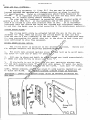
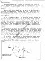
HIVING
KNIFE
HOLD!;;"
DETAIL
The
rivjng
knife
is
supplied
in
the
inverted
position.
fit
upright
adoptinl';
the
following
proceedure:
-(figC3)
Remove
and
1.
Fit
knife
into
grooved
pack:ln,,,:
piece
'E'
and
bolt
up
to
solid
pack-
inp:
piece
'F'
with
the
."
nuts
'G'
provided.
2.
.1"
.\
1.
'G'
has
With
saw
in
plade
set
knife
to
clear
around
sa"
teeth
approximatelY
(6mm)
and
lock
firmly
in
place
with
nuts
'G'
•
If
the
knife
is
not
in
line
with
the
saw,
partially
slacken
nuts
and
jack
packing
piece
'F'
out
,dth
p;rub
screws
'H'
until
the
knife
e~u~l
overhand
either
side
of
the
saw
blade.
Lock
nuts
'G'
firmly.
NOTE:
- BEFORE
RUNNING,
ADJUST
SAl,
GUARD TO
GIVE
t<li\XDlUH
PROTECTION
AND
TO CLEAR SA1,
BLADE.
DO
NOT RUN
HACHINE
I>ITHOUT
GTJARD
IN
POSITION.
INPOf{TANT:
-
t;NSUf{~;
THAT
RIVING
KNIFl;;
BLADE
IS
CORr{ECT
TJIICIGiESS
F(U
SA\!
VSED
j~\
®
I.
-
.~
1\1
\
E
Riving Knife
H
Plate
Riving Knife
www.DaltonsWadkin.com
www.DaltonsWadkin.com
www.DaltonsWadkin.com

-,
-
J
A
K
FIGC4
FIGC4A
www.DaltonsWadkin.com
www.DaltonsWadkin.com
www.DaltonsWadkin.com

10
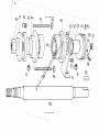
HOUNTING
SAliBLAOES:-
When
mounting
saws
the
undermentioned
proceedure
shoulrl
be
fOllowed:-
1.
Isolate
machine
2.
Remove
table
insert
and
raise
the
saw
spindlp
ho"sing
into
the
top
position.
J.
Remove
spindle
nut
(left
hand
thread)
And
front
saw
flAnge
f'rom
spindle.
4.
Select
blarle
required
depending
on
type
of
work
which
is
to
be
done.
Check
the
hlade
is
in
good
condition
and
free
from
dirt.
sawdust
and
,?,Um.
especiAlly
where
it
will
he
gripped
by
the
SAW
flange.
Hount
saw
on
the
Rpindle
checking
that
the
fac~
of
the
hack
saw
flange
is
clean
And
thAt
the
saw
bore
and
pin
hole
centres
fit
correctly
onto
those
on
the
flange.
').
Check
that
the
saw
teeth
point
towards
the
front
of
the
mAchine
be-
fore
replacing
the
flange
and
locking
up
f'irmly
with
the
spindle
nut.
THPO.tTANT:
-
ENSURE
SPINDLE
il.UNS
IN
COHRECT ClIRI,;CTION, f(8Fj<.;n
TO
SrXTIlJN
..!l..
(ELECTRICS
L
NOTE:-
IF
Tlm
FL.\)IIGE
OR
SA',[
~'ACES
ARE NOT CLlCA'I
TillS
CAN
CAUSE
VIJlHATION
HUE TO THE
SAW
RUNNING
OUT-OF-TRUE.
MITHE
FENCE
(;C.1..p....Jt5)_(EXTRA.)
The
mitre
fence
is
fitted
into
the
groovp
provided
on
the
seo",
t"hle,
which
should
be
kept
clean.
A
scale
is
provirled
to
inrlicate
accurate
setting,
and
a
positive
stop
'A'
is
incorporaterl
in
the
seale
to
give
quick
setting
at
90
0
and
45
0
to
the
saw.
The
plastic
hAnd'"heel
'B'
locks
the
mitre
fence
firmly
in
any
position.
Accurate
repetitive
cutting
can
be
ohtAined
by
USA
of
the
stop
rods
(!'iI':.
CS.)
The
rods
are
held
in
the
fence
with
the
thumbscrews
'C'
and
the
stop
rods
hy
the
two
clamps
'D!
To
adjust
the
stop
ro<ls
slAcken
C1A"'PS
'C'
~nd
'0'
anrl
slide
the
rorls
into
the
position
req'Jired
~s
illustrHted
in
(fig.
C6.)
www.DaltonsWadkin.com
www.DaltonsWadkin.com
www.DaltonsWadkin.com

MITRE
SLOT
STOP
RODS
C
~'----'.
----.
-
-
~
FIGC5
I1
I
!
FIGC6
www.DaltonsWadkin.com
www.DaltonsWadkin.com
www.DaltonsWadkin.com

12
SAli
PACKING.
It
is
usual
to
provioe
a
sa'"
blade
with
some
form
of
packing,
but
it
is
not
intenoed
th"t
this
packing
be
used
as
"
R"uioe
for
buckleo
or
out-of-true
saws.
The
idea
of
fitting
pi-.ckinp,'
piecAs
into
the
table
and
gap
plate
is
to
steady
the
saw,
but
it
should
he
noted
that
the
packing
must
not
be
tight
"s
this
"ill
generate
heat,
resulting
in
a
consequent
loss
of
tension
in
the
blaoe.
The
arrangement
of'
the
saw
packing's
are
in
such
a
way
thRt
"
hard-
wood
mouthpiece
of'
a
length
extending
beyono
the
depth
of
the
saw
teeth
retains
the
f'elt
packinl':
pieces
in
place.
Also
wood
strips
secured
to
the
underside
of'
the
tRhle
and
to
the
front
of'
the
Il'ap
plate
support
the
f'elt
in
position.
At
the
rear
of
thA
g"p
plAte
anrl
table
si.milar
wood
strips
close
the
saw
p;ap
and
provide
a
p;uioe
for
the
saw.
(SEE
nIAGHilHS
OPPOSITE.
)
It
shoulrl
he
noted
thnt
after
some
time,
the
packinll's
will
need
to
he
rene"eo,
ano
sho111(1
not
he
"110,,eo
to
fall
into
b"o
conrlition.
The
rrovision
of'
the
felt
inserts
allow
application
of'
a
s",,,11
amount
of'
lubricating
oil,
which
not
only
cleans
the
saw,
hut
"Iso
re-
ouces
heat
and
burning
whilst
runninp,'.
It
is
therefore
important
that,
at
every
opportunity,
the
felt
pieces
are
1uhricaterl.
NOTE:-
REPLACENENT LENGTHS OF
FELT
l'~7/'l6"
x
6"
.
www.DaltonsWadkin.com
www.DaltonsWadkin.com
www.DaltonsWadkin.com

I
Saw
~
-cr-
1---
I(~"'"
I
I
~L
I
I
I
I
I
I
lEE>
L_
~--
I
----,
I
C)("~e=====:::::::=t==+~:f-.II
Hardw{)j
I
I
a:(B
®:a'
LL-I-4~.~
I I
I
I I
Felt·~+======t=l~~
:
I
I
EBI
.F
FIGC7
--17/Ndl.._I~ardwood
- - mouthpiece
Gap
plate
Saw
SECTION
~A
Saw
Felt
Table
Screw
SECTION
~aa~
Saw
13
Gap Mouth
plate piece
...
:
...
::+
",
/
/h/
X
-
I
/
" / 11-
"-
Table
""...,....,..,.,.'-.r
l
.-.
'1.""
J<
/
If
--1,/
,/
/ I
'i1
I
,"
SECTION~
~CC
www.DaltonsWadkin.com
www.DaltonsWadkin.com
www.DaltonsWadkin.com

14.
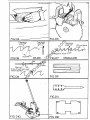
B
FIG
CB
PILLAIl
SAW
GUARD
To
re
ise
and
lower
the
gua
rd,
unlock
lever
'A'
anrl
turn
hanrlle
'B'
(FIG
CB)
To
position
the
guard
on
centre
witll
the
saw,
unlock
lever
'C'
anrl
slirle
the
guard
pillar
'0'
until
th"
guard
is
in
th"
correct
position.
To
centralize
the
guard
to
clear
saw
and
riving
knit'e,
unlock
lever
'E'
and
slide
guard
back
or
forwarc1
aJong
bar
'F'
until
correctly
positioned.
I.hen
operating,
ensure
visor
'G'
is
set
to
clear
timber
by
approximately
in
(Jmm)
To
gain
access
to
saw,
the
guard
cover
will
hinge
up
and
over
to
reve"l
blade.
FIG
C
11
SPINOLE BRAKE:-
This
device
is
operated
from
the
brake
lever
'A'
situated
next
to
the
rise
and
fall
handwheel.
It
is
connected
to
the
brake
pad
by
means
ot'
a
cable
'B'
leading
from
the
operating
lever,
and
is
spring-loaded
to
relieve
tension
",hen
hand
pressure
is
reljeved.
To
tension
the
cable,
turn
the
knurled
nut
'C'
on
the
lever.
Where
excessive
slackness
is
to
be
removed,
unlock
the
grub
screw
'D'
on
the
pillar
at
the
spindle
end
and
pull
cable
through,
re-lock
grub
screw
.md
tensionccable
as
mentioned
above
with
knurled
screw.
l¥hen
re-
placing
brake
pad
it
is
important
that
new
rivets
are
used
and
that
the
rivet
heads
-
are
below
the
surface
of
the
pad
material.
Do
not
a
llow
brake
pad
to
wear
down
to
rivets
as
this
will
score
the
surt'ace
of
the
special
pulley.(FIGC11)
www.DaltonsWadkin.com
www.DaltonsWadkin.com
www.DaltonsWadkin.com

15.
SECTION
"c"
MAINTENANCE
www.DaltonsWadkin.com
www.DaltonsWadkin.com
www.DaltonsWadkin.com

16
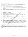
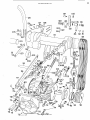
SECTION
D.
-
HAINTENANCE:-
During
the
operating
life
of
the
sawbench
it
may
be
fO\ln<1
necessary
to
replace
worn
or
damaged'pnrts
(i.e.
ba,ll
races.)
To
un<1ertake
this
proceedure
follow
the
undermention<~d
instr\lctions.
(SEE
FIG
D
1.)
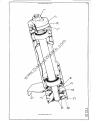
1.
ISOLATF:
?-lAClllNE
ELECTRICALLY
BEFOaE
ATTENPTING
ANY
WORK.
2.
REHOVE G<\P
PLATE,
SAl,
AND
SA1~
SPDlDLE
FRONT
AN·)
H~;AH
COVERS FRON
1'111':
).
4.
5.
6.
8.
'.'.
10.
MACHINE.
SLACKEN AN]) RBHOVE
V-ROPES
FRON
PULLEYS
1\]\1)
HF:~IOVE
TURNnUCKLB
AND
TENSION
STUDS
.\FTER
PAC1CING HOTOR UT'
,\S
SH01{N
IN
(FIG
D.2.)
WIND SAIl'
CARRIAGE
INTO
HIDWAY
POSITION.
REMOVE COUNTERSUNK SCRE1; ANI)
I,ASHSR
'A
t
AND
SLACKEN GRUB SCRE1,rS
'H'
IN
PULLEY
'C'
AND
RENOVE.
RE}iOYE KEY
'D'
AND
DISTANCE
PIF:CE
'E'.
RENOVB
CIRCLIP
'F'
AND
HOTOH
T8NSION
HRACKgT
'G'
ANIl lJNSCHE1,
AND
HEHO
YE
DUSTCAP
'H'.
WORKING
AT
T!lE
FRONT
OF
THg
SAW
SPINDU~t
HENClVE NUT
'I'
(L.H.THHEAD)
AND
SA
IV
FLANGE
'J'.
UNSCfmw
SAt,
FLANGE
'K'
(L.Jl.Tl{Hr;AD.)
HEHClVE
RIVING
KNIFE
PLATE*ANl)
LINK,
AND
UNSCHEW
A~,1l
im)'IOVE
nUST
CAP
t
L'
•
11.
PLACE
A I{oODEN
DRIFT
ON
THE
PULU;Y
EN])
OF
TlIE
SPI:-iDU:
ANIl
f)[(IVE
'I'll"
SHA~'T
THROUGH
Tlm
HOIJSING.
TIY
D01NG
TlIIS
TilE
Sf'INi)LE
\HLL
!';hEHGE
FRO}!
THE
HOPSING
\HTIl
TIlE
SA"
EN')
R8AIUNG
ON
IT.
T)llIVE
THIS
BEAR-
ING
FHON
TilE
SHAFT
AND
RE-INSEaT
SHAFT
INTO
HOrSING
KNUCl:ING
SPINDU:
TITH.OTlGIl
'HTH
HA}IHER
ANT)
mUI'''!'
TO
IlENOvg
THB
PllLLSY
EW)
nEAHING
•
..
To
re-assemble,
reverse
above
proceedure
eneurinr:
all
orie;inal
pFtrts
A
re
thoroughly
cleanerl
out.
*"
It
shoul<1
a.1so
be
note<1
thAt
the·,
two
locknuts
on
thp.
radi"l
slot
in
th
e
ri
vi
nIT
kni
f'e
pla
te
should
only
be
t
iroh
t
enprl
pnour:;h
to
provirle
a
flU
id
e
for
the
motion
of
the
plate
"nrl
not
to
clamp
or
lock
the
plate
in
po"i-
tion.
www.DaltonsWadkin.com
www.DaltonsWadkin.com
www.DaltonsWadkin.com

17
'1
GJ
o
www.DaltonsWadkin.com
www.DaltonsWadkin.com
www.DaltonsWadkin.com

18
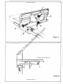
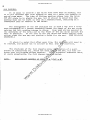
--------~~-----------
BELT
TENSION:-
On
all
mAchines
the
drive
from
the
main
motorto
the
saw
spindle
is
by
means
of'
four
ALPHA
500,
type
"V"
Belts.
To
ensure
maximum
efficiency
and
life.of
these
helts,
it
is
important
that
the
correct
belt
tension
is
maintained
at
all
times
from
new,
especially
in
the
"running
in"
period.
To
tension
the
belts
follow
the
undermen-
tioned
proceedure.
(SEE
FIG.
D.2.)
By
turning
turnbllckle
'A'
linking
the
tension
studs,
the
centre
distance
of
the
pullevs
can
be
increased
to
provide
greater
tension
on
the
belts.
To
achieve
the
correct
tension,
measure
the
centre
distance
of
the
pulleys
(FIG
DJ.)
and
adjust
with
the
turnbuckle
until,
whilst
applying
a
force
at
right
angles
and
central
Along
the
belt,
the
deflec-
tion
is
not
greater
than
1/64"
per
inch
of
span
-
(e.g.
2J"
span
=
2'3/6h"
defle
ct
ion.)
REPLACING
BELTS:-
To
replace
belts,
decrease
pulley
centre
distance
by
screwing
buckle
and
thll"
relievi.ng
tension
on
the
belts
for
their
removal.
wards
retension
as
given
above.
POINTS
TO
NOTE
WHEN
HAINTAINING
BELT
DRIVES:-
1.
2.
J.
4.
ALWA
YS
HAINTAIN
COimECT
BELT
TENSION.
REPLACE
\VOIt"
BELTS
WITH SAl'lE
TYPE
AS
SPECIFIED.
ALtrAYS RF:PLACE
11'OHN
OH
D.\HAGED BELTS
IHHEDIATELY.
ENSURE
PUlLEYS
ARE CORl{ECTLY
ALIGl\ED.
turn-
Aft
er-
5.
DO
NOT
PRISE
BELTS OVER
PULU~YS
\HTH
SCHEl,
DRIVERS
OR OTHER SHARP
IMPLEHENTS
AS
THIS
CA?
DAMAGE
BF;LTS.
6.
,
ENSFRE
PULLEY GHOOVES
AND
BELTS
AHE
CLE:AN
AND
REMOVE
ANY
OIL,
GREASl')
RUST
OR
BURRS 1.11lCIl ARE
PHES~~NT.
www.DaltonsWadkin.com
www.DaltonsWadkin.com
www.DaltonsWadkin.com

Method of packing up
motor for removal of
tension screws as
outlined in sectionDl
I
19
~--+--t---A
FORCE
FIG
D2
FIG
D3
DEFLECTION
1f640F
AN
INCH
PER
INCH
OFSPAN
www.DaltonsWadkin.com
www.DaltonsWadkin.com
www.DaltonsWadkin.com
Strona się ładuje...
Strona się ładuje...
Strona się ładuje...
Strona się ładuje...
Strona się ładuje...
Strona się ładuje...
Strona się ładuje...
Strona się ładuje...
Strona się ładuje...
Strona się ładuje...
Strona się ładuje...
-
 1
1
-
 2
2
-
 3
3
-
 4
4
-
 5
5
-
 6
6
-
 7
7
-
 8
8
-
 9
9
-
 10
10
-
 11
11
-
 12
12
-
 13
13
-
 14
14
-
 15
15
-
 16
16
-
 17
17
-
 18
18
-
 19
19
-
 20
20
-
 21
21
-
 22
22
-
 23
23
-
 24
24
-
 25
25
-
 26
26
-
 27
27
-
 28
28
-
 29
29
-
 30
30
-
 31
31


Wadkin 26BSW Instrukcja obsługi
- Typ
- Instrukcja obsługi
- Niniejsza instrukcja jest również odpowiednia dla
w innych językach
- English: Wadkin 26BSW User manual
Inne dokumenty
-
Luna BCS 250P Original Instructions Manual
-
Scheppach HM100T Original Operating Manual
-
Makita LF1000 Instrukcja obsługi
-
Makita LH1040 Instrukcja obsługi
-
Festool CS 70 EBG-Set Instrukcja obsługi
-
-
Festool CS 50 EBG Instrukcja obsługi
-
-
Parkside PHKS 1300 A1 Operation and Safety Notes
-
Kompernass Saw PHKS 1450 LASER Instrukcja obsługi