Electrolux WIRECONTROL Skrócona instrukcja obsługi
- Typ
- Skrócona instrukcja obsługi

ERB5000AOW
Wire Controller
Boîtier De Commande
Ενσυρματο Χειριστηριο
Comando Via Cavo
Sterownik Przewodowy
Controlador Com Fios
Controlador Por Cable
EN
FR
EL
IT
PL
PT
ES
User Manual
Notice d’utilisation
Εγχειρίδιο χρήσης
Libretto di istruzioni
Instrukcja obsługi
Manual do Utilizador
Manual de instrucciones
2
12
24
36
48
60
72
(en option)
(προαιρετικό)
(opzionale)
(opcjonalnie)
(opcional)
(opcional)
(optional)

2 www.electrolux.com
CONTENTS
1. SAFETY PRECAUTIONS ...................................................................................3
2. SUMMARIZE .......................................................................................................4
3. FUNCTION SUMMARY ......................................................................................4
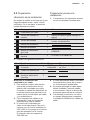
4. NAME AND FUCTION OF INDICATORS ON THE CONTROLLER ....................5
5. INSTALLATION METHOD ...................................................................................6
6. NAME AND OPERATION OF THE BUTTON ON THE WIRE CONTROLLER ...6
7. USING METHOD ................................................................................................8
8. TECHNICAL INDICATION AND REQUIREMENT ...............................................9
9. INSTALLATION ...................................................................................................9
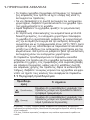
WE’RE THINKING OF YOU
Thank you for choosing this Electrolux product. We have created it to give you impecca-
ble performance for many years, with innovative technologies that help make life simpler
features you might not nd on ordinary appliances. Please spend a few minutes reading
to get the very best from it.
Visit our website to:
Get usage advice, brochures, trouble shooter, service information:
www.electrolux.com
Register your product for better service:
www.electrolux.com/productregistration
Buy Accessories, Consumables and Original spare parts for your appliance:
www.electrolux.com/shop
CUSTOMER CARE AND SERVICE
Always use original spare parts.
When contacting our Authorised Service Centre, ensure that you have the following data
available: Model, PNC, Serial Number.
The information can be found on the rating plate.
Warning / Caution-Safety information.
General information and tips
Environmental information.
Subject to change without notice.

3 ENGLISH
• Thismanualgivesdetaileddescriptionoftheprecautionsthatshould
bebroughttoyourattentionduringoperation
• Inordertoensurecorrectserviceofthewiredcontrollerpleaseread
thismanualcarefullybeforeusingtheunit.
• Forconvenienceoffuturereference,keepthismanualafterreadingit.
• Thewiredcontrollerwillresettofactorysettingwithautomode,auto
fanand24°C(76°F)settingtemperaturewhentheairconditioner
restartsafterpowerfailure.Andthismaycauseinconsistentdisplays
onthewiredcontrollerandontheairconditioner.Youneedtoreadjust
therunningstatusthroughthewiredcontroller.
Thefollowingcontentsarestatedontheproductandtheoperation
manual,includingusage,precautionsagainstpersonalharmandprop-
ertyloss,andthemethodsofusingtheproductcorrectlyandsafely.
Afterfullyunderstandingthefollowingcontents(identiersandicons),
readthetextbodyandobservethefollowingrules.
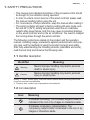
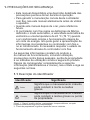
1.1 Identierdescription
Identier Meaning
Warning
Meansimproperhandlingmayleadtopersonal
deathorsevereinjury.
Caution
Meansimproperhandlingmayleadtopersonal
injuryorpropertyloss.
[Note]: 1. “Harm” means injury, burn and electric shock which need long-term treat-
ment but need no hospitalization
2. “Property loss” means loss of properties and materials.
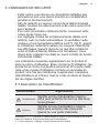
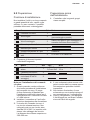
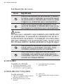
1.2 Icondescription
lcon Meaning
Itindicatesforbidding.Theforbiddensubject-matteris
indicatedintheiconorbyimagesorcharactersaside.
Itindicatescompulsoryimplementation.The
compulsorysubject-matterisindicatedintheiconorby
imagesorcharactersaside.
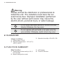
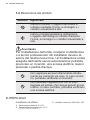
1. SAFETY PRECAUTIONS

4 www.electrolux.com
Warning
Please entrust the distributor or professionals to
install the unit. The installers must have the rel-
evant know-how. Improper installation performed
by the user without perm ission may cause re,
electric,shock, personal injury or water leakage.
Donotsprayammableaerosoltothewirecontroller
directly.Otherwise,remayoccur.
Donotoperatewithwethandsorletwaterenterthe
wirecontroller.Otherwise,electricshockmayoccur.
2. SUMMARIZE
Usage condition:
1. Power supply: 5V DC.
2. Operation temperature: -15°C(-5°F)~
+43°C(+109°F).
3. Operation humidity: 40%-90%, RH.
3. FUNCTION SUMMARY
Main function:
1. Connecting to indoor unit by A, B, C,
D, E terminal;
2. Button setting action mode.
3. LCD display.
4. Timer for rest time.

5 ENGLISH
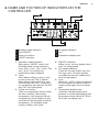
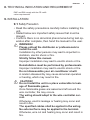
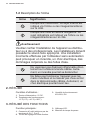
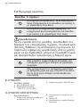
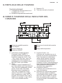
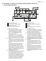
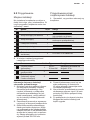
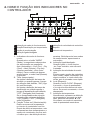
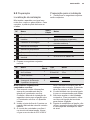
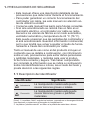
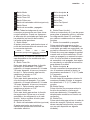
4. NAME AND FUCTION OF INDICATORS ON THE
CONTROLLER
5
1
2
1 121 12
1
2
3
4
5
6
7
1 Operation mode indication
2 Timer ON/OFF
3 Follow me function
4 ON/OFF indication
5 Fan speed indication
6 Lock
7 Temperature display zone
1. Operation mode indication:
When press “ MODE “ button, the
following mode can be selected in
circle. Auto→Cool →Dry→Heat→Fan
only→Auto. For cooling only
model,heat mode is skipped.
2. Timer:
When adjust setting on time or only
on time is set, the “ON” is lighted.
When adjust setting off time or only
off time is set, the “OFF” is lighted. If
on and off timer are both set, the”ON”
and “OFF”are both lighted.
3. Follow me function:
There is a temperature sensor inside
the wire controller, after setting
temperature, it will compare the two
temperatures, and the space of wire
controller will be the same as setting
temperature. It is available under
cooling, heating, auto mode.
4. ON/OFF indication:
When it is on, the icon display, other-
wise it is extinguished.
5. Fan speed indication:
There are four fan modes: low, mid-
dle, high, auto. For some models,
no middle fan then the middle fan is
seen as high speed.
6. Lock:
When the “ LOCK “ button is pressed,
the icon appear and other buttons is
unable, press again, the icon disap-
pear.
7. Temperature display zone:
Generally it displays setting tem-
perature, it can be adjusted by press
temperature button ▲ and ▼. But in
fan mode, no display here.

6 www.electrolux.com
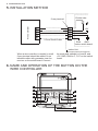
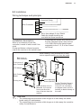
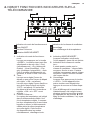
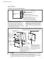
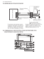
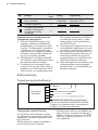
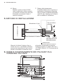
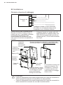
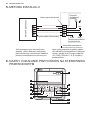
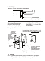
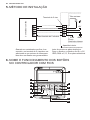
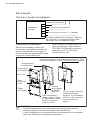
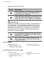
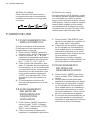
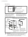
5. INSTALLATION METHOD
When a wire controller is needed, a small
5-way terminal should be added, x an
infrared emitter with gumwater near the
receiver on the switch board. Connect
5-way terminal
Emitter tube
+5V
GNDRUN
Indoor switch board
Indoor Unit
5-Core Shield Cable
Wire Controller
its anode and cathode to A and B, and
+5V, GND, RUN to C, D, E on the switch
board.
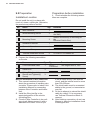
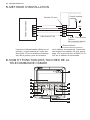
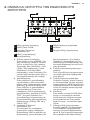
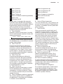
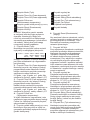
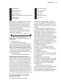
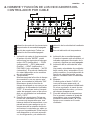
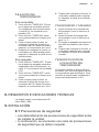
6. NAME AND OPERATION OF THE BUTTON ON THE
WIRE CONTROLLER
1
2
3
4
5
6
8
7
9
10
11
12
13
TIMER
ON
TIMER
OFF
FOLLOW
ME
AUXIL
HEATER
MODE
RESET
LOCK
FAN SPEED
ECO
SWING
TEMP

7 ENGLISH
1 Mode Button
2 Timer On Button
3 Timer Off Button
4 Followe me Button
5 Electrical Heater
Button(optional)
button:(optional)
6 Reset Button
7 On / Off Button
8 Adjust Button ▲
9 Adjust Button ▼
10 Swing Button
11 Economy Button
12 Fan Speed Button
13 Lock Button
NOTE: All the pictures in this manual are
for explanation purpose only. There may
be slightly different from the wire control-
ler you purchased(depend on model).
The actual shape shall prevail.
1. Mode botton:
When press this botton,the operation
mode change as the following sequence:
Remark: For the cooling only model, the
heating mode is skipped.
2. Timer on button:
Press this button, timer on function is ac-
tive. Then every press, the time increase
0.5h, after 10h, 1h increasement after
each press. If cancel this Function,just
set it to “0.0”
3. Timer off button:
Press this button, timer off function is ac-
tive.Then every press, the time increase
0.5h, after 10h, 1h increasement after
each press. If cancel this function, just
set it to “0.0”
4. Follow me button:
When under cool, heat and auto mode,
press this button, follow me function is
active. Press again, this function is inef-
fective.
5. Electrical heater
If press this button in heat mode, electri-
cal heater function become ineffective.
6. Reset button(hidden):
Use a 1mm stick to press in the little
hole, then the current setting is canceled.
The wire controller enter into original
state.
7. ON/OFF button:
When in off state, press this button,
the indicator is on, the wire controller
enter into on state, and send setting
information to indoor Pcb. When in on
state,press this button, the indicator
is off, and send instruction. If timer on
or timer off has been set, it cancel this
setting then send instruction to stop the
machine.
8. Adjust button ▲:
Set indoor temperature up. If press and
hold on, it will increase at 1°C(2°F) per
0.5 second.
9. Adjust button ▼:
Set indoor temperature down if press and
hold on,it will decrease at 1°C(2°F) per
0.5 second.
10. Swing button:
First press, start swing function;second
press, stop swing. (Match to some model
with swing function).
11. Economy operation button:
press this button, the indoor unit oper-
ates in economy mode, press again, exit
this mode (it may be ineffective for some
models)
12. Fan speed button:
press this button consecutively, the fan
speed will circle as follow:
13. Lock button(hidden):
When you push the LOCK button, all cur-
rent settings are locked in and the wire
controller does not accept any operation
except that of the LOCK button. Use the
lock mode when you want to prevent
setting from being changed accidentally
or play fully. Push the LOCK button again
when you want to cancel the LOCK
mode.
→AUTO → COOL→DRY→HEAT→FAN

8 www.electrolux.com
7. USING METHOD
7.1 AUTOMATIC OPERATION
Connect to power,indoor operation lamp
ash.
1. Press “MODE” button, select “AUTO“;
2. Press the button “▲” and “▼”, set
temperature you want, generally it is
among 17°C (62°F) ~30°C (88°F);
3. Press “ ON/OFF” button, operation
lamp is on, the air-conditioner work
in auto mode, indoor fan is auto,
and can not be changed. Auto is
displayed on LCD. Press ON/OFF
button again to stop.
4. Economy operation is valid in auto
mode.
7.2 COOL/HEAT/FAN MODE
OPERATION
1. Press “MODE” button, select
“COOL”, “HEAT” or “FAN ONLY”
mode.
2. Press temperature adjust button to
select setting temp.
3. Press “FAN SPEED” button to select
high/mid/low/auto.
4. Press “ON/OFF” button, indoor unit
operation lamp on, it works in se-
lected mode. Press “ON/OFF” button
again, it stops to work.
Remark: When in fan mode, no tem-
perature can be set.
7.3 DRY OPERATION
1. Press “ MODE “ button, select “ DRY“
mode.
2. Press temperature adjust button to
select setting temp.
3. Press “ ON/OFF “ button, indoor unit
operation lamp on, it works in dry
mode. Press ON/OFF button again, it
stops to work.
4. In dry mode, economy operation and
fan speed are ineffective.
7.4 TIMER SETTING
Timer on only:
1. Press “ TIME ON “ button, it display
“SET” on LCD, and display “ H “ and
“ON”, it is waiting for timer on setting.
2. Press “ timer “ on button repeatedly
to adjust time setting.
3. If press this button and hold on, the
time will increase at 0.5h, after 10h, it
increase at 1h.
4. After setting 0.5 second, the wire
controller send timer on information,
it is nished.
Timer off only:
1. Press “TIME OFF “ button, it display
“SET” on LCD, and display “ H “ and
ON, it is waiting for timer on setting.
2. Press “TIME OFF” button repeatedly
to adjust time setting.
3. If press this button and hold on, the
time will increase at 0.5h, after 10h, it
increase at 1h.
4. After setting 0.5 second, the wire
controller send timer off information,
it is nished.
7.5 TIMER ON AND TIMER
OFF BOTH
1. Set timer on time as the correspond-
ing step1 and 2.
2. Set timer off time as the correspond-
ing step1 and 2.
3. Timer off time must be longer than
timer on time.
4. 0.5 second after setting, the wire
controller send information.the setting
is nished.
7.6 CHANGE TIMER
If there is a need of changing timer time,
press corresponding button to revise it. If
cancel timer, change timer time to 0.0.

9 ENGLISH
8. TECHNICAL INDICATION AND REQUIREMENT
EMC and EMI comply with the CE certi-
cation requirements.
9. INSTALLATION
9.1 SafetyPrecaution
• Read the safety precautions carefully before installing the
unit.
• Stated below are important safety issues that must be
obeyed.
• Conform there is no abnormal phenomena during test op-
eration after complete, then hand the manual to the user.
WARNING!
Please entrust the distributor or professionals to
install the unit.
Installation by other persons may lead to imperfect in-
stallation, electric shock or re.
Strictly follow this manual.
Imporper installation may lead to electric shock or re.
Reinstallation must be performed by professionals.
Improper installation may lead to electric shock or re.
Do not disassemble your air conditioner at will.
A random disassembly may cause abnormal operation
or heating, which may result in re.
CAUTION!
Do not install the unit in a place vulnerable to leak-
age of ammable gases.
Once ammable gases are leaked and left around the
wire controller, re may occure.
The wiring should adapt to the wire controller cur-
rent.
Otherwise, electric leakage or heating may occur and
result in re.
The specied cables shall be applied in the wiring.
No external force may be applied to the terminal.
Otherwise, wire cut and heating may occur and result in
re.

10 www.electrolux.com
9.2 Preparation
Installation Location
Do not install the unit in a place with
much oil, steam, sulde gas. Otherwise,
the product may deform and fail.
Preparation before installation
1. Check whether the following assem-
blies are complete.
No. Name Qty. Remarks
1
Wire controller 1
2
Wood Mounting Screw 3
GB950-86 M4X20(For Mounting on
the Wall)
3
Mounting Screw 3
GB823-88 M4X25(For Mounting on
the
Electrical Switch Box)
4
Installation Manual 1
5
Owner’s Manual 1
6
5-terminal Group 1 RS9005E
7
Terminal Installation Screw 2 ST3.9x12-F-H GB845-85
2. Prepare the following assemblies
on the site.
No. Name Qty. Type Remarks
1
5-core shielded cable 1
RVVP-
0.5mm2x5
The longest wire is 15m
2
Switch box 3
3
Wiring Tube(Insulating
Sleeve and Tightening
Screw)
3
Note to installation of wire controller:
1. This manual contains information
about the procedure of installing wire
controller. Please refer to Indoor Unit
Installation Manual for connecting
between Wire Controller and Indoor
Unit.
2. Install the Wire joint,5p to the
appointed position of the electric
controlling Box.
3. Circuit of Wire Controller is low volt-
age circuit, Never connect it with a
standard 220V/380V circuit or put
it into a same Wiring Tube with the
circuit, and the interval must be more
than 300~500mm.
4. The shield cable must be connected
stable to the ground, or transmission
may fail.
5. Do not to attempt to extend the shield
cable by cutting, if it is necessary,
use Terminal Connection Block to
connect.
6. After nishing connection, do not use
Megger to have the installation check
to the signal wire.

11 ENGLISH
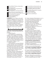
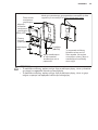
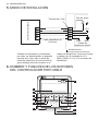
9.3 Installation
Wiring technique and principle:
B
A
C
D
E
Wire Controller
5-terminal Group
Wires here adopts 5-core Shield
Cable,the length should be ac-
cord with the actual conditions.
Installation description:
When it is necessary to use this
controller,it needs to add a small 5-ter-
minal
Group and fasten a infrared emmiter
near to the receiver in the switch board.
Connecting the anode and cathode to A,
B of the Terminal Group, also connect
+5V, GND, RUN of the switch board
separately to the C, D, E of the 5-termi-
nal Group.
Back cover of
Wire Controller
Front cover of
Wire Controller
LCD display
Wire Control
Board
Turning cover
Wood Mounting
Screw (M4X20)
After the back cover is
fastened, to x up the
front cover rst lock
one of the two then the
another.
For the Terminal Group is
standing out of the back
cover, so it is necessary
to obligate holes, and it is
forbiden to fasten directly to
the wall!!
While installing, using Screwdriver or other
tools to open the back cover from the inside
CAUTION!
• The connecting wire should be a little longer as to take away the switch
board easily for maintenance.
• The connecting wire should be a little longer as to take away the controller
easily for maintenance.

12 www.electrolux.com
NOUS PENSONS À VOUS
Merci d'avoir choisi ce produit Electrolux. Nous l'avons conçu pour qu'il vous offre des
performances irréprochables pour longtemps, en intégrant des technologies innovantes
qui vous simplient la vie grâce à des caractéristiques que vous ne trouverez pas for-
cément sur des appareils ordinaires. Veuillez prendre quelques instants pour lire cette
notice an d'utiliser au mieux votre appareil.
Visitez notre site Internet pour :
Obtenir des conseils d'utilisation, des brochures, de l'aide, des informations :
www.electrolux.com
Enregistrer votre produit pour obtenir un meilleur service :
www.electrolux.com/productregistration
Acheter des accessoires, consommables et pièces de rechange d'origine pour
votre appareil :
www.electrolux.com/shop
SERVICE APRÈS-VENTE
Utilisez exclusivement des pièces de rechange d'origine.
Avant de contacter le service, assurez-vous de disposer des informations suivantes :
Modèle, PNC, numéro de série.
Vous trouverez ces informations sur la plaque signalétique.
Avertissement/Attention : informations sur la sécurité.
Informations générales et conseils.
Informations en matière de protection de l'environnement.
Sous réserve de modications.
SOMMAIRE
1. CONSIGNES DE SÉCURITÉ ............................................................................13
2. RÉSUMÉ ...........................................................................................................14
3. RÉSUMÉ DES FONCTIONS ............................................................................14
4. NOM ET FONCTION DES INDICATEURS SUR LA TÉLÉCOMMANDE ..........15
5. MÉTHODE D'INSTALLATION ...........................................................................16
6. NOM ET FONCTION DES TOUCHES DE LA TÉLÉCOMMANDE CÂBLÉE ....16
7. MODE D'UTILISATION .....................................................................................18
8. INDICATION TECHNIQUE ET EXIGENCES ....................................................19
9. INSTALLATION .................................................................................................19

13 FRANÇAIS
• Cette notice vous donne une description détaillée des
précautions que vous devez prendre en considération
pendant le fonctionnement.
• An de garantir un service correct de la télécommande
câblée, veuillez lire attentivement cette notice avant d'uti-
liser l'appareil.
• Pour une consultation ultérieure facile, conservez cette
notice après l'avoir lue.
• Les réglages d'usine de la télécommande câblée sont
rétablis, avec le mode automatique, le ventilateur auto-
matique et une température dénie à 24°C (76°F), quand
le climatiseur redémarre après une coupure d'électricité.
Les afchages risquent alors de ne pas être cohérents
entre la télécommande câblée et le climatiseur. Vous
devez donc réajuster les états en cours à l'aide de la télé-
commande câblée.
Les indications suivantes apparaissent sur le produit et
dans la notice d'utilisation. Elles concernent l'utilisation, les
précautions contre le préjudice personnel et la perte maté-
rielle et les modes d'utilisation correcte et sécurisée du
produit. Une fois les indications ci-après bien comprises,
(identicateurs et icônes), lisez le corps du texte et respec-
tez les règles décrites.
1.1 Description de l'identicateur
Identicateur Signication
Avertissement
Signie qu'une manipulation inappro-
priée peut entraîner la mort ou des bles-
sures graves.
Attention
Signie qu'une manipulation inappro-
priée peut entraîner des blessures
graves ou une perte matérielle.
[Remarque] : 1. 1 « Préjudice » signie blessure, brûlure et choc électrique qui néces-
sitent un traitement à long terme mais pas d'hospitalisation.
2 « Perte matérielle » désigne la perte de biens et de matériel.
1. CONSIGNES DE SÉCURITÉ

14 www.electrolux.com
1.2 Description de l'icône
Icône Signication
Indique une interdiction. Le sujet interdit est
indiqué via l’icône ou les images/caractères
sur le côté.
Indique une mise en œuvre obligatoire. Le
sujet obligatoire est indiqué via l'icône ou les
images/caractères sur le côté.
Avertissement
Veuillez coner l'installation de l'appareil au distribu-
teur ou à des professionnels. Les installateurs doivent
posséder le savoir-faire approprié. Une installation
incorrecte effectuée par l'utilisateur sans autorisation
peut provoquer un incendie, un choc électrique, des
dommages corporels ou des fuites d'eau.
Ne vaporisez pas d'aérosol inammable direc-
tement sur la télécommande câblée. Autre-
ment, un incendie pourrait se déclencher.
Ne faites pas fonctionner l'appareil avec les
mains mouillées et ne laissez pas d'eau entrer
dans la télécommande câblée. Autrement, un
choc électrique pourrait avoir lieu.
2. RÉSUMÉ
Condition d'utilisation :
1. Tension d'alimentation : 5V DC.
2. Température de fonctionnement :
-15°C(-5°F)~ +43°C(+109°F).
3. Humidité de fonctionnement:
40%-90%, RH.
3. RÉSUMÉ DES FONCTIONS
Fonction principale :
1. Connexion à l'unité intérieure par les
terminaux A, B, C, D et E.
2. Touche de réglage du mode d'action.
3. Afchage LCD.
4. Minuteur du temps de pause.

15 FRANÇAIS
4. NOM ET FONCTION DES INDICATEURS SUR LA
TÉLÉCOMMANDE
5
1
2
1 121 12
1
2
3
4
5
6
7
1 Indication du mode de fonctionnement
2 Timer ON/OFF
3 Fonction Follow me
4 Indication MARCHE/ARRÊT
5 Indication de la vitesse du ventilateur
6 Verrouillage
7 Zone d'afchage de la température
1. Indication du mode de fonctionne-
ment :
Lorsque vous appuyez sur la touche
« MODE », le mode suivant peut être
sélectionné en boucle. Auto→Cool
(refroidissement) →Dry (déshumidi-
cation) →Heat (chauffage) →Fan
only (ventilateur uniquement) →Auto.
Pour le modèle refroidissement uni-
quement, le mode « Heat » est omis.
2. Timer :
Lorsque vous réglez l'heure de
départ ou que seule l'heure de départ
est réglée, « ON » est allumé.
Lorsque vous réglez l'heure d'arrêt ou
que seule l'heure d'arrêt est réglée,
« OFF » est allumé. Si les heures
de départ et d'arrêt sont toutes deux
réglées, « ON » et « OFF » sont
allumés.
3. Fonction Follow me :
Un capteur de température est intégré
dans la télécommande câblée. Une
fois la température réglée, il compare
les deux températures et la zone dans
laquelle se trouve la télécommande
câblée atteint la même température
que celle réglée. Cette fonction
est disponible dans les modes
refroidissement, chauffage et auto.
4. Indication MARCHE/ARRÊT :
Lorsque l'indication est allumée,
l'icône apparaît, sinon elle est éteinte.
5. Indication de la vitesse du ventila-
teur :
Il existe quatre modes pour la
vitesse du ventilateur : vitesse faible,
moyenne, élevée et auto. Certains
modèles ne proposent pas de vitesse
moyenne. Celle-ci est donc considé-
rée comme élevée.
6. Verrouillage :
Lorsque vous appuyez sur la touche
« LOCK », l'icône apparaît et les
autres touches sont désactivées.
Appuyez à nouveau et l'icône dispa-
raît.
7. Zone d'afchage de la température :
Habituellement, elle indique la tem-
pérature réglée qui peut être ajustée
en appuyant sur les touches ▲ et ▼.
Mais en mode ventilateur, il n'y a pas
d'afchage.

16 www.electrolux.com
5. MÉTHODE D'INSTALLATION
Lorsqu'une télécommande câblée est né-
cessaire, un petit terminal à 5 voies doit
être ajouté. Fixez un émetteur infrarouge
avec de la gomme, près du recepteur,
Terminal à 5 voies
Conduit émetteur
+5V
Prise de terreRUN
Tableau
de commande intérieur
Élément intérieur
Câble blindé à 5 ls
Télécommande câblée
sur le tableau de commande. Connectez
son anode et sa cathode à A et B, puis la
prise +5V, la prise de terre et RUN à C, D
et E sur le tableau de commande.
6. NOM ET FONCTION DES TOUCHES DE LA
TÉLÉCOMMANDE CÂBLÉE
1
2
3
4
5
6
8
7
9
10
11
12
13
TIMER
ON
TIMER
OFF
FOLLOW
ME
AUXIL
HEATER
MODE
RESET
LOCK
FAN SPEED
ECO
SWING
TEMP

17 FRANÇAIS
1 Touche Mode
2 Touche Timer ON
3 Touche Timer OFF
4 Touche Follow me
5 Touche Auxil
Heater
:
(en option)
(en option)
6 Touche Reset
7 Touche Marche/Arrêt
8 Touche de réglage ▲
9 Touche de réglage ▼
10 Touche Swing
11 Touche Eco
12 Touche Fan Speed
13 Touche Lock
REMARQUE : Toutes les illustrations
incluses dans cette notice sont four-
nies à titre indicatif uniquement. Elles
peuvent être légèrement différentes sur
la télécommande câblée que vous avez
achetée (selon le modèle). La forme
réelle prévaut.
1. Touche Mode :
Lorsque vous appuyez sur cette touche,
le mode de fonctionnement change dans
l'ordre suivant :
Remarque: Pour le modèle refroidis-
sement uniquement, le mode Heat est
omis.
2. Touche Timer On :
Appuyez sur cette touche pour activer
la fonction Timer On. Ensuite, chaque
nouvel appui effectué sur la touche aug-
mente la durée d'une demie heure, puis
d'une heure, au-delà de 10 h. Si vous
voulez annuler cette fonction, réglez-la
simplement sur « 0 »
3. Touche Timer OFF :
Appuyez sur cette touche pour activer
la fonction Timer OFF. Ensuite, chaque
nouvel appui effectué sur la touche aug-
mente la durée d'une demie heure, puis
d'une heure, au-delà de 10 h. Si vous
voulez annuler cette fonction, réglez-la
simplement sur « 0 »
4. Touche Follow me :
Lorsque l'appareil est en mode refroidis-
sement, chauffage et auto, appuyez sur
cette touche pour activer la fonction Fol-
low me. Appuyez de nouveau sur cette
touche pour annuler cette fonction.
5. Touche Auxil Heater
Si vous appuyez sur ce bouton en mode
Heat (chauffage), la fonction chauffage
électrique est désactivée.
6. Touche Reset (cachée) :
Utilisez un bâtonnet de 1 mm pour
exercer une pression dans le petit trou.
Le réglage actuel est alors annulé. La
télécommande câblée retrouve son état
d'origine.
7. Touche MARCHE/ARRÊT :
Lorsque l'appareil est en mode arrêt,
appuyez sur cette touche. L'indicateur
s'allume, la télécommande câblée passe
en mode marche et envoie des informa-
tions de réglage au climatiseur intérieur.
Lorsque l'appareil est en mode marche,
appuyez sur cette touche. L'indicateur
s'éteint et envoie une instruction. Si la
fonction Timer ON ou OFF a été réglée,
ce réglage est annulé et l'instruction
d'arrêt de l'appareil est envoyée.
8. Touche de réglage ▲ :
Augmente la température intérieure. Si
vous appuyez et maintenez la touche
enfoncée, la température augmente de
1°C (2°F) à chaque demie seconde.
9. Touche de réglage ▼ :
Si vous appuyez et maintenez la touche
enfoncée, la température intérieure
baisse de 1°C (2°F) à chaque demie
seconde.
10. Touche Swing :
Le premier appui démarre la fonction
Swing, le second l'arrête. (Correspond
à certains modèles dotés de la fonction
Swing).
11. Touche Eco :
Appuyez sur cette touche pour faire
fonctionner l'élément intérieur en mode
économie. Appuyez à nouveau sur cette
touche pour quitter ce mode (éventuelle-
ment inapplicable à certains modèles).
→AUTO → COOL→DRY→HEAT→FAN

18 www.electrolux.com
7. MODE D'UTILISATION
7.1 MODE AUTOMATIQUE
À la mise sous tension, la lumière de
fonctionnement intérieur clignote.
1. Appuyez sur la touche « MODE »,
sélectionnez « AUTO ».
2. Appuyez sur les touches « ▲ » et
« ▼ », réglez la température souhai-
tée, généralement comprise entre
17°C (62°F) et 30°C (88°F).
3. Appuyez sur la touche Marche/
Arrêt, la lumière de fonctionnement
s'allume, le climatiseur fonctionne en
mode auto, le ventilateur intérieur est
en mode auto et vous ne pouvez pas
le modier. « Auto » s'inscrit sur l'af-
chage LCD. Appuyez à nouveau sur
la touche Marche/Arrêt pour arrêter
ce mode.
4. Le mode Eco est compatible avec le
mode Auto.
7.2 MODE COOL/HEAT/FAN
(REFROIDISSEMENT/
CHAUFFAGE/VENTILA-
TEUR)
1. Appuyez sur la touche « MODE »,
sélectionnez le mode « COOL »
(refroidissement), « HEAT » (chauf-
fage) ou « FAN ONLY » (ventilateur
uniquement).
2. Appuyez sur la touche de réglage de
la température pour sélectionner la
température de réglage.
3. Appuyez sur le bouton « FAN
SPEED » (vitesse du ventilateur)
pour sélectionner high/mid/low/auto
(élevée/moyenne/faible/auto).
4. Appuyez sur la touche Marche/Arrêt,
la lumière de fonctionnement inté-
rieur s'allume et l'appareil fonctionne
dans le mode sélectionné. Appuyez à
nouveau sur la touche Marche/Arrêt,
l'appareil s'arrête de fonctionner.
5. Remarque: En mode « Fan » (ven-
tilateur), la température ne peut pas
être réglée.
7.3 MODE DRY
(DÉSHUMIDIFATION)
1. Appuyez sur la touche « MODE »,
sélectionnez le mode « DRY » (dés-
humidication).
2. Appuyez sur la touche de réglage de
la température pour sélectionner la
température de réglage.
3. Appuyez sur la touche Marche/Arrêt,
la lumière de fonctionnement inté-
rieur s'allume et l'appareil fonctionne
en mode déshumidication. Appuyez
à nouveau sur la touche ON/OFF,
l'appareil s'arrête de fonctionner.
4. En mode déshumidication, le mode
Eco et le mode Fan Speed ne fonc-
tionnent pas.
12. Touche Fan speed
(vitesse du ventilateur) :
Appuyez sur cette touche plusieurs fois
pour modier la vitesse du ventilateur
dans l'ordre suivant :
13. Touche Lock (cachée) :
Lorsque vous appuyez sur la touche
LOCK (verrouillage), tous les para-
mètres en cours sont verrouillés et la
télécommande câblée n'accepte aucune
commande à l'exception d'un appui sur
la touche LOCK. Utilisez le mode LOCK
(verrouillage) pour empêcher toute
modication accidentelle des réglages.
Appuyez de nouveau sur la touche LOCK
lorsque vous souhaitez annuler le mode
LOCK.

19 FRANÇAIS
8. INDICATION TECHNIQUE ET EXIGENCES
EMC et EMI sont conformes aux exi-
gences de certication CE.
9. INSTALLATION
9.1 Consignes de sécurité
• Lisez attentivement les consignes de sécurité avant d’ins-
taller l’appareil.
• Sont stipulées ci-après des instructions à suivre impor-
tantes relatives à la sécurité.
• Vériez qu'aucun phénomène anormal ne se produit
durant les tests, puis remettez la notice à l'utilisateur.
7.4 RÉGLAGE DU MODE
TIMER :
Timer On seulement :
1. Appuyez sur la touche « TIMER
ON ». « SET » s'afche sur l'écran
LCD, puis « H » et « ON ». L'appareil
attend alors le réglage de la fonction
Timer On.
2. Appuyez plusieurs fois sur la touche
« TIMER ON » pour ajuster le
réglage.
3. Si vous appuyez sur cette touche
en la maintenant enfoncée, la durée
augmente par tranche d'une demie
heure, et au-delà de 10 heures, par
tranche d'une heure.
4. Une demie seconde après le réglage,
la télécommande câblée envoie les
informations. Le réglage est terminé.
Timer Off seulement :
1. Appuyez sur la touche « TIMER
OFF ». « SET » s'afche sur l'écran
LCD, puis « H » et « ON ». L'appareil
attend alors le réglage de la fonction
Timer On.
2. Appuyez plusieurs fois sur la touche
« TIMER OFF » pour ajuster le
réglage.
3. Si vous appuyez sur cette touche
en la maintenant enfoncée, la durée
augmente par tranche d'une demie
heure, et au-delà de 10 heures, par
tranche d'une heure.
4. Une demie seconde après le réglage,
la télécommande câblée envoie les
informations. Le réglage est terminé.
7.5 TIMER ON ET TIMER OFF
ENSEMBLE
1. Réglez la fonction Timer On comme
aux étapes 1 et 2 correspondantes.
2. Réglez la fonction Timer Off comme
aux étapes 1 et 2 correspondantes.
3. La durée de la fonction Timer Off doit
être supérieure à celle de la fonction
Timer On.
4. Une demie seconde après le réglage,
la télécommande câblée envoie les
informations. Le réglage est terminé.
7.6 MODIFIER LA FONCTION
TIMER
Si vous devez modier la fonction Timer,
appuyez sur la touche correspondante.
Pour annuler la fonction Timer, réglez-la
sur 0.0.

20 www.electrolux.com
ATTENTION !
Veuillez coner l'installation de l'appareil au distri-
buteur ou à des professionnels.
Des installations effectuées par d'autres personnes
peuvent entraîner des installations défectueuses, des
chocs électriques ou un incendie.
Suivez strictement cette notice.
Une mauvaise installation peut entraîner un choc élec-
trique ou un incendie.
Toute nouvelle installation doit être effectuée par
des professionnels.
Une mauvaise installation peut entraîner un choc élec-
trique ou un incendie.
Ne démontez pas votre climatiseur à votre guise.
Un démontage effectué de façon aléatoire peut provo-
quer un dysfonctionnement ou un chauffage anormal,
lequel peut entraîner un incendie.
ATTENTION !
N'installez pas l'appareil à un endroit vulnérable aux
fuites de gaz inammables.
Une fois que des gaz inammables s'échappent et
entourent la télécommande câblée, un incendie peut
survenir.
L'installation électrique doit être adaptée au courant
de la télécommande câblée.
Sans quoi des courts-circuits ou des surchauffes
peuvent survenir et entraîner un incendie.
Les câbles spéciés doivent être utilisés dans l'ins-
tallation électrique. Aucune force externe ne doit
être exercée sur le terminal.
Sans quoi une coupure de câble et des surchauffe
peuvent survenir et entraîner un incendie.
Strona się ładuje...
Strona się ładuje...
Strona się ładuje...
Strona się ładuje...
Strona się ładuje...
Strona się ładuje...
Strona się ładuje...
Strona się ładuje...
Strona się ładuje...
Strona się ładuje...
Strona się ładuje...
Strona się ładuje...
Strona się ładuje...
Strona się ładuje...
Strona się ładuje...
Strona się ładuje...
Strona się ładuje...
Strona się ładuje...
Strona się ładuje...
Strona się ładuje...
Strona się ładuje...
Strona się ładuje...
Strona się ładuje...
Strona się ładuje...
Strona się ładuje...
Strona się ładuje...
Strona się ładuje...
Strona się ładuje...
Strona się ładuje...
Strona się ładuje...
Strona się ładuje...
Strona się ładuje...
Strona się ładuje...
Strona się ładuje...
Strona się ładuje...
Strona się ładuje...
Strona się ładuje...
Strona się ładuje...
Strona się ładuje...
Strona się ładuje...
Strona się ładuje...
Strona się ładuje...
Strona się ładuje...
Strona się ładuje...
Strona się ładuje...
Strona się ładuje...
Strona się ładuje...
Strona się ładuje...
Strona się ładuje...
Strona się ładuje...
Strona się ładuje...
Strona się ładuje...
Strona się ładuje...
Strona się ładuje...
Strona się ładuje...
Strona się ładuje...
Strona się ładuje...
Strona się ładuje...
Strona się ładuje...
Strona się ładuje...
Strona się ładuje...
Strona się ładuje...
Strona się ładuje...
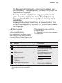
Strona się ładuje...
-
 1
1
-
 2
2
-
 3
3
-
 4
4
-
 5
5
-
 6
6
-
 7
7
-
 8
8
-
 9
9
-
 10
10
-
 11
11
-
 12
12
-
 13
13
-
 14
14
-
 15
15
-
 16
16
-
 17
17
-
 18
18
-
 19
19
-
 20
20
-
 21
21
-
 22
22
-
 23
23
-
 24
24
-
 25
25
-
 26
26
-
 27
27
-
 28
28
-
 29
29
-
 30
30
-
 31
31
-
 32
32
-
 33
33
-
 34
34
-
 35
35
-
 36
36
-
 37
37
-
 38
38
-
 39
39
-
 40
40
-
 41
41
-
 42
42
-
 43
43
-
 44
44
-
 45
45
-
 46
46
-
 47
47
-
 48
48
-
 49
49
-
 50
50
-
 51
51
-
 52
52
-
 53
53
-
 54
54
-
 55
55
-
 56
56
-
 57
57
-
 58
58
-
 59
59
-
 60
60
-
 61
61
-
 62
62
-
 63
63
-
 64
64
-
 65
65
-
 66
66
-
 67
67
-
 68
68
-
 69
69
-
 70
70
-
 71
71
-
 72
72
-
 73
73
-
 74
74
-
 75
75
-
 76
76
-
 77
77
-
 78
78
-
 79
79
-
 80
80
-
 81
81
-
 82
82
-
 83
83
-
 84
84


Electrolux WIRECONTROL Skrócona instrukcja obsługi
- Typ
- Skrócona instrukcja obsługi
w innych językach
- español: Electrolux WIRECONTROL Guía de inicio rápido
- italiano: Electrolux WIRECONTROL Guida Rapida
- português: Electrolux WIRECONTROL Guia rápido
- français: Electrolux WIRECONTROL Guide de démarrage rapide
- English: Electrolux WIRECONTROL Quick start guide
Powiązane artykuły
Inne dokumenty
-
LG S12BF Instrukcja obsługi
-
LG UV42H.NL1 Instrukcja obsługi
-
Haier AS07NS3HRA Operation Manual And Installation Manual
-
LG BS-H0964DM0 Instrukcja obsługi
-
LG MC12AHV Instrukcja obsługi
-
Megger MIT400/2 Series Instrukcja obsługi
-
ELDOM WG100 TOLL Instrukcja obsługi
-
Taurus Alpatec RCMB 27 Instrukcja obsługi
-
Panasonic CZ-RTC6 Wired Remote Controller Instrukcja obsługi