
Synthesizer Parameter Manual
EN
EN
Introduction
This manual explains the parameters and technical terms that are used for synthesizers
incorporating the Yamaha AWM2 sound generators.
You should use this manual together with the documentation unique to the product. Read the
documentation first and use this parameter manual to learn more about parameters and terms
that relate to Yamaha synthesizers. We hope that this manual gives you a detailed and
comprehensive understanding of Yamaha synthesizers.
Information
The contents of this manual and the copyrights thereof are under exclusive ownership by
Yamaha Corporation.
The company names and product names in this manual are the trademarks or registered
trademarks of their respective companies.
Some functions and parameters in this manual may not be provided in your product.
The information in this manual is current as of October 2010.

2
Table Of Contents
1 Voice Parameters . . . . . . . . . . . . . . . . . . . . . . . . . . . . . . . . . . . . . . . 4
1-1 Basic Terms . . . . . . . . . . . . . . . . . . . . . . . . . . . . . . . . . . . . . . . . . . . . 4
1-1-1 Definitions . . . . . . . . . . . . . . . . . . . . . . . . . . . . . . . . . . . . . . . . 4
1-2 Synthesis Parameters . . . . . . . . . . . . . . . . . . . . . . . . . . . . . . . . . . . . . 5
1-2-1 Oscillator . . . . . . . . . . . . . . . . . . . . . . . . . . . . . . . . . . . . . . . . . 5
1-2-2 Pitch . . . . . . . . . . . . . . . . . . . . . . . . . . . . . . . . . . . . . . . . . . . . 8
1-2-3 Pitch EG (Pitch Envelope Generator) . . . . . . . . . . . . . . . . . . . 9
1-2-4 Filter . . . . . . . . . . . . . . . . . . . . . . . . . . . . . . . . . . . . . . . . . . . 13
1-2-5 Filter Type . . . . . . . . . . . . . . . . . . . . . . . . . . . . . . . . . . . . . . . 16
1-2-6 Filter EG (Envelope Generator) . . . . . . . . . . . . . . . . . . . . . . 22
1-2-7 Filter Scale . . . . . . . . . . . . . . . . . . . . . . . . . . . . . . . . . . . . . . 26
1-2-8 Amplitude . . . . . . . . . . . . . . . . . . . . . . . . . . . . . . . . . . . . . . . 27
1-2-9 Amplitude EG (Envelope Generator) . . . . . . . . . . . . . . . . . . 31
1-2-10 Amplitude Scale . . . . . . . . . . . . . . . . . . . . . . . . . . . . . . . . . . 33
1-2-11 LFO (Low-Frequency Oscillator) . . . . . . . . . . . . . . . . . . . . . . 34
1-3 Operational Parameters . . . . . . . . . . . . . . . . . . . . . . . . . . . . . . . . . . 41
1-3-1 General . . . . . . . . . . . . . . . . . . . . . . . . . . . . . . . . . . . . . . . . . 41
1-3-2 Play Mode . . . . . . . . . . . . . . . . . . . . . . . . . . . . . . . . . . . . . . . 41
1-3-3 Portamento . . . . . . . . . . . . . . . . . . . . . . . . . . . . . . . . . . . . . . 42
1-3-4 Micro Tuning List . . . . . . . . . . . . . . . . . . . . . . . . . . . . . . . . . 43
1-3-5 Arpeggio . . . . . . . . . . . . . . . . . . . . . . . . . . . . . . . . . . . . . . . . 44
1-3-6 Controller Set . . . . . . . . . . . . . . . . . . . . . . . . . . . . . . . . . . . . 47
1-3-7 Effect . . . . . . . . . . . . . . . . . . . . . . . . . . . . . . . . . . . . . . . . . . . 48
1-3-8 EQ (Equalizer) . . . . . . . . . . . . . . . . . . . . . . . . . . . . . . . . . . . 50
2 Effects . . . . . . . . . . . . . . . . . . . . . . . . . . . . . . . . . . . . . . . . . . . . . . . 52
2-1 Basic Terms . . . . . . . . . . . . . . . . . . . . . . . . . . . . . . . . . . . . . . . . . . . 52
2-1-1 Definisions . . . . . . . . . . . . . . . . . . . . . . . . . . . . . . . . . . . . . . 52
2-2 Effect Types . . . . . . . . . . . . . . . . . . . . . . . . . . . . . . . . . . . . . . . . . . . 52
2-2-1 Reverb . . . . . . . . . . . . . . . . . . . . . . . . . . . . . . . . . . . . . . . . . 52
2-2-2 Delay . . . . . . . . . . . . . . . . . . . . . . . . . . . . . . . . . . . . . . . . . . . 52
2-2-3 Chorus . . . . . . . . . . . . . . . . . . . . . . . . . . . . . . . . . . . . . . . . . 53
2-2-4 Flanger . . . . . . . . . . . . . . . . . . . . . . . . . . . . . . . . . . . . . . . . . 53
2-2-5 Phaser . . . . . . . . . . . . . . . . . . . . . . . . . . . . . . . . . . . . . . . . . 53
2-2-6 Tremolo & Rotary . . . . . . . . . . . . . . . . . . . . . . . . . . . . . . . . . 54
2-2-7 Distortion . . . . . . . . . . . . . . . . . . . . . . . . . . . . . . . . . . . . . . . . 54
2-2-8 Compressor . . . . . . . . . . . . . . . . . . . . . . . . . . . . . . . . . . . . . 54
2-2-9 Wah . . . . . . . . . . . . . . . . . . . . . . . . . . . . . . . . . . . . . . . . . . . 54
2-2-10 Lo-Fi . . . . . . . . . . . . . . . . . . . . . . . . . . . . . . . . . . . . . . . . . . . 55
2-2-11 Tech . . . . . . . . . . . . . . . . . . . . . . . . . . . . . . . . . . . . . . . . . . . 55
2-2-12 Vocoder . . . . . . . . . . . . . . . . . . . . . . . . . . . . . . . . . . . . . . . . 55
2-2-13 Misc . . . . . . . . . . . . . . . . . . . . . . . . . . . . . . . . . . . . . . . . . . . 55
2-3 Effect Parameters . . . . . . . . . . . . . . . . . . . . . . . . . . . . . . . . . . . . . . . 56
2-3-1 A . . . . . . . . . . . . . . . . . . . . . . . . . . . . . . . . . . . . . . . . . . . . . . 56
2-3-2 B . . . . . . . . . . . . . . . . . . . . . . . . . . . . . . . . . . . . . . . . . . . . . . 56
2-3-3 C . . . . . . . . . . . . . . . . . . . . . . . . . . . . . . . . . . . . . . . . . . . . . . 56
2-3-4 D . . . . . . . . . . . . . . . . . . . . . . . . . . . . . . . . . . . . . . . . . . . . . . 57

3
2-3-5 E . . . . . . . . . . . . . . . . . . . . . . . . . . . . . . . . . . . . . . . . . . . . . . 58
2-3-6 F . . . . . . . . . . . . . . . . . . . . . . . . . . . . . . . . . . . . . . . . . . . . . . 59
2-3-7 G . . . . . . . . . . . . . . . . . . . . . . . . . . . . . . . . . . . . . . . . . . . . . . 60
2-3-8 H . . . . . . . . . . . . . . . . . . . . . . . . . . . . . . . . . . . . . . . . . . . . . . 60
2-3-9 I . . . . . . . . . . . . . . . . . . . . . . . . . . . . . . . . . . . . . . . . . . . . . . . 60
2-3-10 L . . . . . . . . . . . . . . . . . . . . . . . . . . . . . . . . . . . . . . . . . . . . . . 61
2-3-11 M . . . . . . . . . . . . . . . . . . . . . . . . . . . . . . . . . . . . . . . . . . . . . . 62
2-3-12 N . . . . . . . . . . . . . . . . . . . . . . . . . . . . . . . . . . . . . . . . . . . . . . 63
2-3-13 O . . . . . . . . . . . . . . . . . . . . . . . . . . . . . . . . . . . . . . . . . . . . . . 63
2-3-14 P . . . . . . . . . . . . . . . . . . . . . . . . . . . . . . . . . . . . . . . . . . . . . . 63
2-3-15 R . . . . . . . . . . . . . . . . . . . . . . . . . . . . . . . . . . . . . . . . . . . . . . 64
2-3-16 S . . . . . . . . . . . . . . . . . . . . . . . . . . . . . . . . . . . . . . . . . . . . . . 64
2-3-17 T . . . . . . . . . . . . . . . . . . . . . . . . . . . . . . . . . . . . . . . . . . . . . . 65
2-3-18 V . . . . . . . . . . . . . . . . . . . . . . . . . . . . . . . . . . . . . . . . . . . . . . 65
2-3-19 W . . . . . . . . . . . . . . . . . . . . . . . . . . . . . . . . . . . . . . . . . . . . . 65
3 MIDI . . . . . . . . . . . . . . . . . . . . . . . . . . . . . . . . . . . . . . . . . . . . . . . . . 66
3-1 Overview . . . . . . . . . . . . . . . . . . . . . . . . . . . . . . . . . . . . . . . . . . . . . . 66
3-1-1 About MIDI . . . . . . . . . . . . . . . . . . . . . . . . . . . . . . . . . . . . . . 66
3-1-2 MIDI channels . . . . . . . . . . . . . . . . . . . . . . . . . . . . . . . . . . . . 66
3-1-3 MIDI ports . . . . . . . . . . . . . . . . . . . . . . . . . . . . . . . . . . . . . . . 67
3-1-4 MIDI messages . . . . . . . . . . . . . . . . . . . . . . . . . . . . . . . . . . . 67
3-2 Channel Messages . . . . . . . . . . . . . . . . . . . . . . . . . . . . . . . . . . . . . . 68
3-2-1 Note On/Off . . . . . . . . . . . . . . . . . . . . . . . . . . . . . . . . . . . . . . 68
3-2-2 Pitch Bend . . . . . . . . . . . . . . . . . . . . . . . . . . . . . . . . . . . . . . 68
3-2-3 Program Change . . . . . . . . . . . . . . . . . . . . . . . . . . . . . . . . . 68
3-2-4 Control Change . . . . . . . . . . . . . . . . . . . . . . . . . . . . . . . . . . . 68
3-2-5 Channel Mode message . . . . . . . . . . . . . . . . . . . . . . . . . . . . 71
3-2-6 Channel After Touch . . . . . . . . . . . . . . . . . . . . . . . . . . . . . . . 71
3-2-7 Polyphonic After Touch . . . . . . . . . . . . . . . . . . . . . . . . . . . . . 71
3-3 System Messages . . . . . . . . . . . . . . . . . . . . . . . . . . . . . . . . . . . . . . 72
3-3-1 System Exclusive Messages . . . . . . . . . . . . . . . . . . . . . . . . 72
3-3-2 System Common Message . . . . . . . . . . . . . . . . . . . . . . . . . . 72
3-3-3 System Realtime Messages . . . . . . . . . . . . . . . . . . . . . . . . . 72

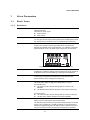
Voice Parameters
4
1 Voice Parameters
1-1 Basic Terms
1-1-1 Definitions
Voice A Voice is a musical instrument sound that is built into an Electronic
Musical Instrument.
There are two Voice Types:
Normal Voices
Drum Voices
Normal Voice Normal Voices are mainly pitched musical instrument-type sounds.
You can play over the range of the keyboard at the standard pitch for each
key. Normal Voices consist of one or more Elements (see "Element").
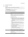
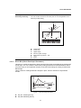
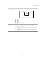
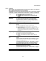
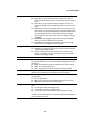
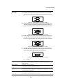
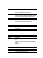
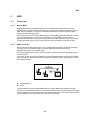
Drum Voice Drum Voices are mainly percussion/drum sounds.
A Drum Voice consists of mainly percussion/drum sounds that are
assigned to individual notes on the keyboard, or a collection of assigned
percussion/drum waves. The Drum Voice is also known as a Drum Kit.
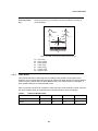
Figure 1: Individual drum sounds, different for each key.
Element An Element is the smallest unit that makes up a Normal Voice.
An Element is created by applying Voice Parameters to sound material. A
single Normal Voice can be created by combining several Elements.
Drum Key A Drum Key is the smallest unit that makes up a Drum Voice.
A Drum Key is assigned to individual notes on the Keyboard. The
percussion/Drum wave is assigned to a Drum Key.
Voice Edit A function that lets you create your own Voices.
Use Voice Edit to adjust or apply Voice Parameters to a Voice.
For Normal Voices:
Use Common Edit to edit the settings that are common to all
Elements;
Use Element Edit to edit the settings for each Element separately.
For Drum Voices:
Use Common Edit to edit the settings that are common to all keys;
Use Key Edit to edit the settings for each key separately.
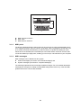
GM General MIDI (GM) is a worldwide standard for Voice organization and
MIDI functions of synthesizers and tone generators.
This standard ensures that any song sounds virtually the same on any GM
device of any manufacturer. The GM Voice Bank on this synthesizer is
designed to appropriately play back GM song data. However, the sound
may not be exactly the same as played by the original tone generator.
C0 C1 C6

Voice Parameters
5
1-2 Synthesis Parameters
1-2-1 Oscillator
An Oscillator outputs the waveform that determines the basic pitch of an Element and is one
unit of the tone generator block of the Electronic Musical Instrument.
You can:
Assign the waveform (or basic sound material) to each Element of a Normal Voice or each
key of a Drum Voice;
Set the note range for the Element (Normal Voice);
Set the Velocity response (Normal Voice);
Set the XA (eXpanded Articulation) parameters.
Element Switch Switches a selected Element On or Off.
Elements for which the Element Switch is switched off will not sound.
XA Control Determines the functioning of the Expanded Articulation (XA) feature of an
Element.
The XA feature is sophisticated tone generator system that allows you to
more effectively recreate realistic sound and natural performance
techniques. It also provides other unique modes for random and alternate
sound changes as you play.
For each Element, you can set to:
Normal: The Element sounds normally each time you play the note.
Legato: When the Mono/Poly parameter is set to Mono, this Element
will be played in place of the one which is set to "Normal" of the XA
Control parameter when you play the keyboard in legato fashion
(playing the next note of a single-note line or melody before releasing
the previous note).
Key off sound: The Element will sound each time you release the
note.
Wave cycle (for multiple Elements): Each Element sounds
alternately according to its numerical order. In other words, playing
the first note will sound Element 1, the second note Element 2, and
so on.
Wave random (for multiple Elements): Each Element will sound
randomly each time you play the note.
AF 1 on: When the ASSIGNABLE FUNCTION [1] button is turned
On, the Element will sound.
AF 2 on: When the ASSIGNABLE FUNCTION [2] button is turned
On, the Element will sound.
All AF off: When both the ASSIGNABLE FUNCTION [1] and [2]
buttons are turned Off, the Element will sound.
To create the desired sound, assign the same Element Group to all
Elements that have the same XA features. See "Element Group".
Element Group Determines the group for XA Control.
The Elements of a group can be called up in sequential order or in random
order. All Elements that have the same type of XA features must have the
same group number.
This setting does not apply when the XA Control parameters of all
Elements are set to Normal.

Voice Parameters
6
Waveform Bank Specifies the Waveform Bank of an Element or Drum Key (Drum Voice).
Preset
User: This lets you create User Waveforms based on samples that
are recorded in the Sampling mode.
Waveform Category and
Number
Specifies the waveform of an Element (Normal Voice) or Drum Key (Drum
Voice).
The waveform is specified as a combination of a Waveform Category and
a Waveform Number.
Assign Mode (for Drum
Voices)
Enables or disables double playback of the same note.
Single: Double or repeated playback of the same note is not possible.
The first note will be stopped, then the next note will be sounded.
Multi: All notes are sounded simultaneously. This allows playback of
the same note when it is played multiple times in succession
(especially for tambourine and cymbal sounds that you would want to
ring out to their full decay).
In general, you can use the setting Multi. Keep in mind that the Multi
setting consumes overall polyphony and that sounds may be cut off.
Receive Note Off (for
Drum Voices)
Determines whether a Drum Key responds to the MIDI Note Off message
or not.
On: Stops the sound when you release the key (Drum Key). For
sustained, non-fading drum sounds.
Off: Continues the (fading) sound when you release the key (Drum
Key).
Alternate Group (for
Drum Voices)
Prevents playback of unnatural combinations of Drum Keys.
You should assign Drum Keys that cannot be played simultaneously on a
real Drum Kit (like open and closed hi-hats) to the same Alternate Group.
Select Off for Drum Keys that can be played simultaneously.
Key On Delay Defines the time delay between when a key is pressed and the
corresponding sound is actually played.
The higher the value, the longer the delay time.
Delay Tempo Sync Determines if the Key On Delay is synchronized to the tempo of the
Arpeggio or sequencer (Song or Pattern).
Delay Tempo Determines the timing of the Key On Delay when the Delay Tempo Sync
is set to On.
Velocity Cross Fade Determines how gradually the volume of an Element decreases in
proportion to the distance of Velocity changes outside the Velocity Limit
setting.
The higher the value, the more gradual the volume decreases.
0: No sound outside the Velocity Limit (see "Velocity Limit") is
produced.
Use this parameter to create natural-sounding Velocity cross fades, in
which different Elements change gradually depending on the strength at
which you play the keyboard.

Voice Parameters
7
Velocity Limit Determines the minimum and maximum Velocity values in which an
Element responds.
Each Element will only sound for notes played between its specified
Velocity Limits.
For example, this lets you have one Element sound when you play softly
and have a different one sound when you play strongly.
If you first specify the maximum value and then the minimum value, for
example "93 to 34," then the Velocity range covers both "1 to 34" and
"93to127."
Note Limit Determines the lowest and highest notes of the keyboard range for an
Element.
The selected Element will sound only when you play notes within this
range.
If you first specify the highest note and then the lowest note, for example
"C5 to C4", then the note range covers both "C-2 to C4" and "C5 to G8."

Voice Parameters
8
1-2-2 Pitch
The processing unit that controls the pitch of the wave output from the Oscillator on the tone
generator block of the Electronic Musical Instrument.
This unit controls the pitch of the sound (wave) output from the Oscillator. In the case of a
Normal Voice, you can detune separate Elements, apply Pitch Scaling and so on. Also, by
setting the Pitch Envelope Generator (Pitch EG), you can control how the pitch changes over
time.
Coarse Tuning Determines the pitch of each Element (Normal Voice) or each Drum Key
(Drum Voice) in semitones.
Fine Tuning Determines the pitch of each Element or each Drum Key in cents.
The term "cent" refers to one hundredth of a semitone (i.e., 100 cents = 1
semitone).
Pitch Velocity Sensitivity Determines how the pitch of the Element or Drum Key responds to
Velocity.
Positive values: The pitch rises more, the harder you play the
keyboard.
Negative values: The pitch falls more, the harder you play the
keyboard.
0: No change in pitch.
Fine Scaling Sensitivity Determines the degree to which the notes (specifically, their position or
Octave Range) affect the pitch in Fine Tuning of the selected Element,
assuming C3 as the basic pitch.
Positive values: The pitch of lower notes drops and that of higher
notes rises.
Negative values: The pitch of lower notes rises and that of higher
notes drops.
Random This lets you randomly vary the pitch of the Element for each note you play.
The higher the value, the greater the pitch variation.
0: No pitch change.
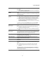
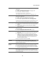
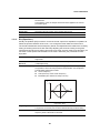
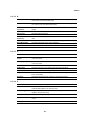
Pitch Key Follow
Sensitivity
Determines the sensitivity of the Key Follow effect (the pitch interval of
adjacent notes), assuming the pitch of the Center Key as standard.
+100% (the normal setting): Adjacent notes are pitched one semitone
apart.
0%: All notes are the same pitch specified as the Center Key.
Negative values: The settings are reversed.
This parameter is useful for creating alternate tunings, or for use with
sounds that do not need to be spaced in semitones, such as pitched drum
sounds in a Normal Voice.

Voice Parameters
9
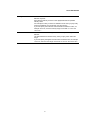
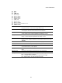
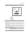
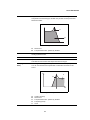
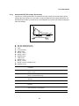
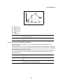
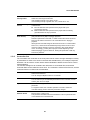
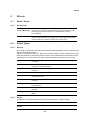
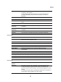
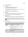
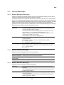
1-2-3 Pitch EG (Pitch Envelope Generator)
This lets you control the transition in pitch from the moment the sound starts to the moment the
sound stops. You can create the Pitch EG by setting parameters as illustrated below. When
you press a key on the keyboard, the pitch of the Voice will change according to these Pitch
EG settings.
This is useful for creating automatic changes in pitch, which is effective for Synth Brass
sounds.
Figure 3: Pitch Envelope Generator
A: Key On: Pressing the key
B: Key Off: Releasing the key
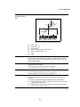
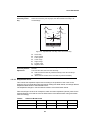
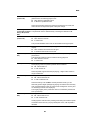
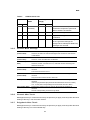
Pitch Key Follow
Sensitivity Center Key
Determines the central note or pitch for Pitch Key Follow.
The note number set here is the same pitch as normal regardless of the
Pitch Key Follow setting.
Figure 2: Pitch Key Follow and Center Key
A: Lower range
B: Center Key
C: Higher range
D: Amount of pitch change
E: When Pitch Key Follow = 100
F: Large
G: Small
+
–
D
E
F
G
B
C
A
D
E
F
GH I
0
B
C
A
K
L
M
N
J

Voice Parameters
10
C: Time
D: Pitch
E: Hold Time
F: Attack Time
G: Decay 1 Time
H: Decay 2 Time
I: Release Time
J: Hold Level
K: Attack Level
L: Decay 1 Level
M: Decay 2 Level = Sustain Level
N: Release Level
Hold Time Determines the time between the moment you press a key on the
keyboard and the moment the envelope starts to rise.
Attack Time Determines the speed of attack from the initial pitch (Hold Level) to the
normal pitch of the Voice after the hold time has elapsed.
Decay 1 Time Determines how fast the envelope falls from the normal pitch (Attack
Level) of the Voice to the pitch specified as the Decay 1 Level.
Decay 2 Time Determines how fast the envelope falls from the pitch specified as the
Decay 1 Level to the pitch specified as the Decay 2 Level.
Release Time Determines how fast the envelope falls from the pitch specified as the
Decay 2 Level to the pitch specified as the Release Level when the note is
released.
Hold Level Determines the initial pitch at the moment the key is pressed.
Attack Level Determines the normal pitch of the pressed key.
Decay 1 Level Determines the level which the pitch of sound reaches from the Attack
Level after the Decay 1 time elapses.
Decay 2 Level Determines the sustain-level pitch which will be maintained while a note is
held.
Release Level Determines the final pitch reached after the note is released.
EG Depth Determines the range over which the pitch envelope changes.
0: The pitch does not change.
The farther from 0 the value is, the larger the pitch range.
Negative values: The pitch change is reversed.

Voice Parameters
11
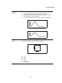
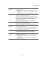
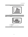
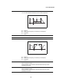
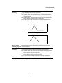
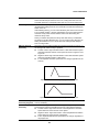
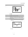
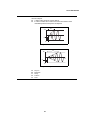
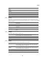
EG Depth Velocity
Sensitivity
Determines how the pitch range of the Element responds to Velocity.
Positive values: High Velocities cause the pitch range to expand and
low Velocities cause it to contract, as shown in Figure 4.
Negative values: High Velocities cause the pitch range to contract
and low Velocities cause it to expand.
0: The pitch envelope does not change, regardless of the Velocity.
Figure 4: High Velocity, large range
Figure 5: Low Velocity, small range
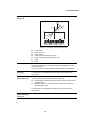
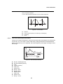
EG Depth Velocity
Curve
Determines how the pitch range will be generated according to the Velocity
(strength) with which you play notes on the keyboard.
Figure 6: Pitch EG Depth Velocity Curve
A: Low
B: High
C: Low
D: High
X: Velocity
Y: Pitch Change
D
B
C
Y
A
X

Voice Parameters
12
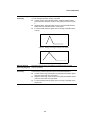
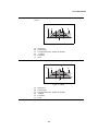
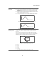
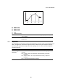
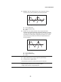
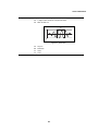
EG Time Velocity
Sensitivity
Determines how the Pitch EG transition time (speed) responds to Velocity,
or to the strength with which the key is pressed.
Positive values: High Velocities result in a fast Pitch EG transition
speed while low Velocities result in a slow speed, as shown in Figure
7.
Negative values: High Velocities result in a slow Pitch EG transition
speed while low Velocities result in a fast speed.
0: The Pitch EG transition speed does not change, regardless of the
Velocity.
Figure 7: Playing hard (high Velocity): fast speed
Figure 8: Playing softly (low Velocity): slow speed
EG Time Velocity
Sensitivity Segment
Determines the part of the Pitch EG that is affected by the EG Time
Velocity Sensitivity.
EG Time Key Follow
Sensitivity
Determines the degree to which the notes (specifically, their position or
Octave Range) affect the pitch EG times of the selected Element.
Positive values: High notes result in a high pitch EG transition speed
while low notes result in a slow speed.
Negative values: High notes result in a slow pitch EG transition speed
while low notes result in a high speed.
0: The pitch EG transition speed does not change, regardless of the
played note.

Voice Parameters
13
1-2-4 Filter
A filter is a circuit or processor that modifies tone by blocking or passing a specific frequency
range of the sound.
Filters work by allowing portions of the signal lower or higher than a given frequency to pass,
and cutting the remainder of the signal. This given frequency is referred to as the Cutoff
Frequency. You can produce a relatively brighter or darker sound depending on how you set
the Cutoff Frequency.
By adjusting the Resonance (which boosts the level of the signal in the area of the Cutoff
Frequency), you can produce a distinctive "peaky" tone, making the sound brighter and harder.
On the tone generator block of the Electronic Musical Instrument, the sound signal output from
the Pitch unit is processed by the Filter unit.
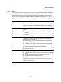
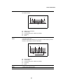
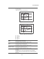
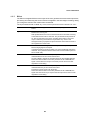
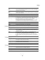
EG Time Key Follow
Sensitivity Center
Key
Determines the central note or pitch for the EG Time Key Follow.
When the Center Key note is played, the Pitch EG behaves according to
its actual settings.
Figure 9: Pitch EG Time Key Follow and Center Key
A: Center Key
B: Slower Speed
C: Faster Speed
D: Lower range
E: Higher range
F: Positive value
G: Negative value
+63
+30
-40
B
A
DE
C
F
G
Cutoff Frequency Determines the Cutoff Frequency for the Filter, or the central frequency
around which the Filter is applied.
The tonal characteristics of the Voice and function of the Cutoff Frequency
differ depending on which Filter Type is selected (see Chapter 1-2-5 Filter
Type).

Voice Parameters
14
Cutoff Velocity
Sensitivity
Determines how the Cutoff Frequency responds to Velocity, or the strength
with which you play notes.
Positive values: The Cutoff Frequency rises the stronger you play the
keyboard.
Negative values: The Cutoff Frequency rises the softer you play the
keyboard.
0: The Cutoff Frequency does not change, regardless of the Velocity.
Resonance Resonance is used to set the amount of Resonance (harmonic emphasis)
applied to the signal at the Cutoff Frequency.
This parameter can boost the level of the signal in the area of the Cutoff
Frequency. By emphasizing the overtones in this area, this can produce a
distinctive "peaky" tone, making the sound brighter and harder.
This can be used in combination with the Cutoff Frequency parameter to
add further character to the sound.
This parameter is available when an LPF, HPF, BPF (excluding the
BPFw), or BEF is selected as a Filter Type.
Width The Width parameter is used to adjust the width of the band of signal
frequencies passed by the filter with the BPFw.
This parameter is available when a BPFw is selected as a Filter Type.
Resonance Velocity
Sensitivity
Determines the degree to which Resonance responds to Velocity, or the
strength with which you play notes.
Positive values: The higher the Velocity, the greater the Resonance.
Negative values: The lower the Velocity, the greater the Resonance.
0: No change of the Resonance value.
Gain Determines the Gain of the signal sent to the filter.
The lower the value, the lower the Gain. The tonal characteristics
generated by the filter differ depending on the value set here.
Cutoff Key Follow
Sensitivity
Determines the degree to which the notes (specifically, their position or
Octave Range) affect the Cutoff Frequency of the selected Element,
assuming C3 as the basic pitch.
Positive values: The Cutoff Frequency drops for lower notes and rises
for higher notes.
Negative values: The Cutoff Frequency rises for lower notes and
drops for higher notes.

Voice Parameters
15
Cutoff Key Follow
Center Key
This indicates the central note for Cutoff Key Follow.
Figure 10: Cutoff Key Follow and Center Key
A: Lower range
B: Center Key = C3
C: Higher range
D: Amount of Cutoff Frequency change
E: When Cutoff Key Follow Sensitivity = 100
F: Large
G: Small
Distance Determines the Distance between the two Cutoff Frequencies of the Dual
Filter Types (which consist of two identical filters in parallel), and of the
LPF12+BPF6 type.
When any other Filter Type is selected, this parameter is not available.
HPF Cutoff
Frequency
Determines the central frequency for the Key Follow parameter of the HPF.
This parameter is only available for Filter Types LPF12+HPF12 and
LPF6+HPF6.
HPF Cutoff Key
Follow Sensitivity
Determines the degree to which the notes (specifically, their position or
Octave Range) affect the Cutoff Frequency of the HPF.
Positive values: The Cutoff Frequency drops for lower notes and rises
for higher notes.
Negative values: The Cutoff Frequency rises for lower notes and
drops for higher notes.
This parameter is only available for Filter Types LPF12+HPF12 and
LPF6+HPF6.
HPF Cutoff Key
Follow Sensitivity
Center Key
This indicates the central note for HPF Key Follow Sensitivity.
+
–
D
E
F
G
B
C
A

Voice Parameters
16
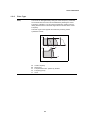
1-2-5 Filter Type
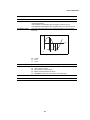
LPF (Low-Pass
Filter)
This is a Filter Type that only passes signals below the Cutoff Frequency.
The sound can be brightened by raising the Cutoff Frequency of the filter.
On the other hand, the sound can be darkened by lowering the Cutoff
Frequency of the filter. You can produce a distinctive "peaky" sound by
raising the Resonance to boost the signal level in the area of the Cutoff
Frequency.
This Filter Type is most popular and useful for producing classic
synthesizer sounds.
Figure 11: Low-Pass Filter
A: Cutoff Frequency
B: Resonance
C: Frequencies that are “passed” by the filter
X: Frequency (Pitch)
Y: Level
CA
B
X
A
X
Y
Y

Voice Parameters
17
LPF24D A dynamic -24 dB/oct Low-Pass Filter with a characteristic digital sound.
Compared to the LPF24A type, this filter can produce a more pronounced
Resonance effect.
Figure 12: LPF24D
A: Resonance
B: Frequencies that are “passed” by the filter
LPF24A A digital dynamic Low-Pass Filter with characteristics similar to a 4-pole
analog synthesizer filter.
LPF18 3-pole -18 dB/oct Low-Pass Filter.
LPF18s 3-pole -18 dB/oct Low-Pass Filter.
This filter has a smoother cutoff slope than the LPF18 type.
HPF (High-Pass
Filter)
A Filter Type that only passes signals above the Cutoff Frequency.
You can use the Resonance parameter to add further character to the
sound.
Figure 13: High-Pass Filter
A: Cutoff Frequency
B: Resonance
C: Frequencies that are “passed” by the filter
X: Frequency (Pitch)
Y: Level
A
B
C
A
B
X
Y

Voice Parameters
18
HPF24D A dynamic -24 dB/oct High-Pass Filter with a characteristic digital sound.
This filter can produce a pronounced Resonance effect.
Figure 14: HPF24D
A: Resonance
HPF12 -12 dB/oct dynamic High-Pass Filter.
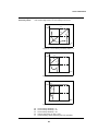
BPF (Band-Pass
Filter)
A Filter Type that only passes a band of signals around the Cutoff
Frequency.
Figure 15: Band-Pass Filter
A: Center Frequency
B: Cutoff Range
C: Frequencies that are “passed” by the filter
X: Frequency
Y: Level
A
Y
B
A
X
C

Voice Parameters
19
BPF12D The combination of a -12 dB/oct HPF and LPF with a characteristic digital
sound.
Figure 16: BPF12D
A: Resonance
B: Cutoff Range
C: Frequencies that are “passed” by the filter
D: -12 dB/oct
X: Frequency
Y: Level
BPF6 The combination of a -6 dB/oct HPF and LPF.
Figure 17: BPF6
A: Resonance
B: Cutoff Range
C: Frequencies that are “passed” by the filter
D: -6 dB/oct
X: Frequency
Y: Level
Y
BB
A
C
X
D
Y
BB
A
C
X
D

Voice Parameters
20
BPFw A -12 dB/oct BPF that combines HPF and LPF filters to allow wider
bandwidth settings.
Figure 18: BPFw
A: Width can be increased
B: Cutoff Range
C: Frequencies that are “passed” by the filter
X: Frequency
Y: Level
BEF (Band-Eliminate
Filter)
The Band-Eliminate Filter has an opposite effect on the sound compared
to the Band-Pass Filter.
When this Filter Type is selected, you can set the Cutoff Frequency around
which the audio signal is muted or eliminated.
Figure 19: Band-Eliminate Filter
A: Center Frequency
B: Cutoff Range
C: Frequencies that are “passed” by the filter
X: Frequency
Y: Level
BEF12 -12 dB/oct Band-Eliminate Filter.
BEF6 -6 dB/oct Band-Eliminate Filter.
Y
B
B
C
X
A
Y
B
C
X
A
Strona się ładuje...
Strona się ładuje...
Strona się ładuje...
Strona się ładuje...
Strona się ładuje...
Strona się ładuje...
Strona się ładuje...
Strona się ładuje...
Strona się ładuje...
Strona się ładuje...
Strona się ładuje...
Strona się ładuje...
Strona się ładuje...
Strona się ładuje...
Strona się ładuje...
Strona się ładuje...
Strona się ładuje...
Strona się ładuje...
Strona się ładuje...
Strona się ładuje...
Strona się ładuje...
Strona się ładuje...
Strona się ładuje...
Strona się ładuje...
Strona się ładuje...
Strona się ładuje...
Strona się ładuje...
Strona się ładuje...
Strona się ładuje...
Strona się ładuje...
Strona się ładuje...
Strona się ładuje...
Strona się ładuje...
Strona się ładuje...
Strona się ładuje...
Strona się ładuje...
Strona się ładuje...
Strona się ładuje...
Strona się ładuje...
Strona się ładuje...
Strona się ładuje...
Strona się ładuje...
Strona się ładuje...
Strona się ładuje...
Strona się ładuje...
Strona się ładuje...
Strona się ładuje...
Strona się ładuje...
Strona się ładuje...
Strona się ładuje...
Strona się ładuje...
Strona się ładuje...
Strona się ładuje...
Strona się ładuje...
-
 1
1
-
 2
2
-
 3
3
-
 4
4
-
 5
5
-
 6
6
-
 7
7
-
 8
8
-
 9
9
-
 10
10
-
 11
11
-
 12
12
-
 13
13
-
 14
14
-
 15
15
-
 16
16
-
 17
17
-
 18
18
-
 19
19
-
 20
20
-
 21
21
-
 22
22
-
 23
23
-
 24
24
-
 25
25
-
 26
26
-
 27
27
-
 28
28
-
 29
29
-
 30
30
-
 31
31
-
 32
32
-
 33
33
-
 34
34
-
 35
35
-
 36
36
-
 37
37
-
 38
38
-
 39
39
-
 40
40
-
 41
41
-
 42
42
-
 43
43
-
 44
44
-
 45
45
-
 46
46
-
 47
47
-
 48
48
-
 49
49
-
 50
50
-
 51
51
-
 52
52
-
 53
53
-
 54
54
-
 55
55
-
 56
56
-
 57
57
-
 58
58
-
 59
59
-
 60
60
-
 61
61
-
 62
62
-
 63
63
-
 64
64
-
 65
65
-
 66
66
-
 67
67
-
 68
68
-
 69
69
-
 70
70
-
 71
71
-
 72
72
-
 73
73
-
 74
74


Yamaha CP4 Instrukcja obsługi
- Kategoria
- Perkusja muzyczna
- Typ
- Instrukcja obsługi
w innych językach
- čeština: Yamaha CP4 Uživatelský manuál
- español: Yamaha CP4 Manual de usuario
- italiano: Yamaha CP4 Manuale utente
- Deutsch: Yamaha CP4 Benutzerhandbuch
- svenska: Yamaha CP4 Användarmanual
- português: Yamaha CP4 Manual do usuário
- français: Yamaha CP4 Manuel utilisateur
- Türkçe: Yamaha CP4 Kullanım kılavuzu
- English: Yamaha CP4 User manual
- dansk: Yamaha CP4 Brugermanual
- русский: Yamaha CP4 Руководство пользователя
- suomi: Yamaha CP4 Ohjekirja
- Nederlands: Yamaha CP4 Handleiding
- română: Yamaha CP4 Manual de utilizare
Powiązane artykuły
-
Yamaha MONTAGE6 Instrukcja obsługi
-
-
-
-
Yamaha MOTIF7 Instrukcja obsługi
-
-
-
Yamaha MODX7 Instrukcja obsługi
-
-

