Behringer ABACUS Skrócona instrukcja obsługi
- Typ
- Skrócona instrukcja obsługi

Quick Start Guide
ABACUS
Analog Music Computer for Eurorack
V 0.0

2 3Quick Start Guide
ABACUS
(EN) Safety
Instruction
1. Read these instructions.
2. Keep these instructions.
3. Heed all warnings.
4. Follow all instructions.
5. Do not use this apparatus
near water.
6. Clean only with
dry cloth.
7. Do not block any
ventilation openings. Install
in accordance with the
manufacturer’s instructions.
8. Do not install near
any heat sources such as
radiators, heat registers,
stoves, or other apparatus
(including ampli ers) that
produce heat.
9. Use only attachments/
accessories speci ed by
themanufacturer.
10. Use
only with the
cart, stand,
tripod, bracket,
or table speci ed by the
manufacturer, or sold with
the apparatus. When a cart is
used, use caution when
moving the cart/apparatus
combination to avoid injury
from tip-over.
11. Correct
disposal of
this product:
This symbol
indicates that
this product must not be
disposed of with household
waste, according to the
WEEE Directive (2012/19/EU)
and your national law.
This product should be taken
to a collection center licensed
for the recycling of waste
electrical and electronic
equipment (EEE).
The mishandling of this type
of waste could have a
possible negative impact on
the environment and human
health due to potentially
hazardous substances that
are generally associated
with EEE. At the same time,
your cooperation in the
correct disposal of this
product will contribute to the
effi cient use of natural
resources. For more
information about where you
can take your waste
equipment for recycling,
please contact your local
city offi ce, or your household
waste collection service.
12. Do not install in a
con ned space, such as a
book case or similar unit.
13. Do not place naked
ame sources, such as lighted
candles, on the apparatus.
(ES) Instrucción de
seguridad
1. Lea las instrucciones.
2. Conserve estas
instrucciones.
3. Preste atención a todas
las advertencias.
4. Siga todas las
instrucciones.
5. No use este aparato
cerca del agua.
6. Limpie este aparato con
un paño seco.
7.
No bloquee las aberturas
de ventilación. Instale el
equipo de acuerdo con las
instrucciones del fabricante.
8. No instale este equipo
cerca de fuentes de calor
tales como radiadores,
acumuladores de calor,
estufas u otros aparatos
(incluyendo ampli cadores)
que puedan producir calor.
9. Use únicamente los
dispositivos o accesorios
especi cados por el
fabricante.
10. Use
únicamente la
carretilla,
plataforma,
trípode, soporte o mesa
especi cados por el
fabricante o suministrados
junto con el equipo.
Al transportar el equipo,
11.
Cómo debe
deshacerse de
este aparato:
Este símbolo
indica que este aparato no
debe ser tratado como basura
orgánica, según lo indicado
en la Directiva WEEE
(2012/19/EU) y a las
normativas aplicables en su
país. En lugar de ello deberá
llevarlo al punto limpio más
cercano para el reciclaje de
sus elementos eléctricos/
electrónicos (EEE). Al hacer
esto estará ayudando a
prevenir las posibles
consecuencias negativas para
el medio ambiente y la salud
que podrían ser provocadas
por una gestión inadecuada
de este tipo de aparatos.
Además, el reciclaje de
materiales ayudará a
conservar los recursos
naturales. Para más
información acerca del
reciclaje de este aparato,
póngase en contacto con el
Ayuntamiento de su ciudad o
con el punto limpio local.
12. No instale esta unidad
en un espacio muy reducido,
tal como encastrada en una
librería o similar.
13. No coloque objetos
con llama, como una vela
encendida, sobre este
aparato.
(FR) Consignes de
sécurité
1. Lisez ces consignes.
2. Conservez ces consignes.
3. Respectez tous les
avertissements.
4. Respectez toutes les
consignes d’utilisation.
5. N’utilisez jamais
l’appareil à proximité d’un
liquide.
6. Nettoyez l’appareil avec
un chi on sec.
7. Veillez à ne pas
empêcher la bonne
ventilation de l’appareil via
ses ouïes de ventilation.
Respectezles consignes
du fabricant concernant
l’installation del’appareil.
8. Ne placez pas l’appareil
à proximité d’une source de
chaleur telle qu’un chau age,
une cuisinière ou tout
appareil dégageant de la
chaleur (y compris un ampli
depuissance).
9. Utilisez exclusivement
des accessoires et des
appareils supplémentaires
recommandés par
lefabricant.
10. Utilisez
exclusivement
des chariots,
des diables, des
présentoirs, despieds et des
surfaces de travail
recommandés par le
fabricant ou livrés avec le
produit. Déplacez
précautionneusement tout
chariot ou diable chargé pour
éviter d’éventuelles blessures
en cas de chute.
11. Mise
au rebut
appropriée de
ce produit:
Ce symbole
indique qu’en accord avec la
directive DEEE (2012/19/EU)
et les lois en vigueur dans
votre pays, ce produit ne doit
pas être jeté avec les déchets
ménagers. Ce produit doit
être déposé dans un point de
collecte agréé pour le
recyclage des déchets
d’équipements électriques et
électroniques (EEE). Une
mauvaise manipulation de ce
type de déchets pourrait
avoir un impact négatif sur
l’environnement et la santé à

4 5Quick Start Guide
ABACUS
cause des substances
potentiellement dangereuses
généralement associées à ces
équipements. En même
temps, votre coopération
dans la mise au rebut de ce
produit contribuera à
l’utilisation effi cace des
ressources naturelles.
Pour plus d’informations sur
l’endroit où vous pouvez
déposer vos déchets
d’équipements pour le
recyclage, veuillez contacter
votre mairie ou votre centre
local de collecte des déchets.
12. N’installez pas l’appareil
dans un espace con né tel
qu’une bibliothèque ou
meuble similaire.
13. Ne placez jamais
d’objets en ammés, tels que
des bougies allumées,
sur l’appareil.
(DE) Wichtige
Sicherhteitshinweise
1. Lesen Sie diese
Hinweise.
2. Bewahren Sie diese
Hinweise auf.
3. Beachten Sie alle
Warnhinweise.
4. Befolgen Sie alle
Bedienungshinweise.
5. Betreiben Sie das Gerät
nicht in der Nähe vonWasser.
6. Reinigen Sie das Gerät
mit einem trockenen Tuch.
7. Blockieren Sie nicht die
Belüftungsschlitze. Beachten
Sie beim Einbau des Gerätes
die Herstellerhinweise.
8. Stellen Sie das Gerät
nicht in der Nähe von
Wärmequellen auf. Solche
Wärmequellen sind z. B.
Heizkörper, Herde oder
andere Wärme erzeugende
Geräte (auch Verstärker).
9. Verwenden Sie nur
Zusatzgeräte/Zubehörteile,
dielaut Hersteller
geeignet sind.
10.
Verwenden Sie
nur Wagen,
Stand-vorrich-
tungen, Stative, Halter oder
Tische, die vom Hersteller
benannt oder im
Lieferumfang des Geräts
enthalten sind. Falls Sie einen
Wagen benutzen, seien Sie
vorsichtig beim Bewegen der
Wagen- Gerätkombination,
umVerletzungen durch
Stolpern zuvermeiden.
11. Korrekte
Entsorgung
dieses
Produkts:
Dieses Symbol
weist darauf hin, das Produkt
entsprechend der WEEE
Direktive (2012/19/EU) und
der jeweiligen nationalen
Gesetze nicht zusammen mit
Ihren Haushaltsabfällen zu
entsorgen. DiesesProdukt
sollte bei einer autorisierten
Sammelstelle für Recycling
elektrischer und
elektronischer Geräte (EEE)
abgegeben werden. Wegen
bedenklicher Substanzen,
diegenerell mit elektrischen
und elektronischen Geräten
in Verbindung stehen, könnte
eine unsachgemäße
Behandlung dieser Abfallart
eine negative Auswirkung
auf Umwelt und Gesundheit
haben. Gleichzeitig
gewährleistet Ihr Beitrag zur
richtigen Entsorgung dieses
Produkts die e ektive
Nutzung natürlicher
Ressourcen. Fürweitere
Informationen zur
Entsorgung Ihrer Geräte bei
einer Recycling-Stelle
nehmen Sie bitte Kontakt
zum zuständigen städtischen
Büro, Entsorgungsamt oder
zu Ihrem
Haushaltsabfallentsorger
auf.
12. Installieren Sie das
Gerät nicht in einer beengten
Umgebung, zum Beispiel
Bücherregal oder ähnliches.
13. Stellen Sie keine
Gegenstände mit o enen
Flammen, etwa brennende
Kerzen, auf das Gerät.
(PT) Instruções
de Seguranç
Importantes
1. Leia estas instruções.
2. Guarde estas instruções.
3. Preste atenção a todos
os avisos.
4. Siga todas as instruções.
5. Não utilize este
dispositivo perto de água.
6. Limpe apenas com um
pano seco.
7. Não obstrua as entradas
de ventilação. Instale de
acordo com as instruções do
fabricante.
8. Não instale perto de
quaisquer fontes de calor
tais como radiadores, bocas
de ar quente, fogões de
sala ou outros aparelhos
(incluindo ampli cadores)
que produzam calor.
9. Utilize apenas ligações/
acessórios especi cados
pelofabricante.
10. Utilize
apenas com o
carrinho,
estrutura, tripé,
suporte, ou mesa
especi cados pelo fabricante
ou vendidos com o
dispositivo. Quandoutilizar
um carrinho, tenha cuidado
ao mover o conjunto
carrinho/dispositivo para
evitar danos provocados pela
terpidação.
11. Correcta
eliminação
deste produto:
este símbolo
indica que o
produto não deve ser
eliminado juntamente com
os resíduos domésticos,
segundo a Directiva REEE
(2012/19/EU) e a legislação
nacional. Este produto deverá
ser levado para um centro de
recolha licenciado para a
reciclagem de resíduos de
equipamentos eléctricos e
electrónicos (EEE). O
tratamento incorrecto deste
tipo de resíduos pode ter um
eventual impacto negativo
no ambiente e na saúde
humana devido a substâncias
potencialmente perigosas
que estão geralmente
associadas aos EEE. Ao
mesmo tempo, a sua
colaboração para a
eliminação correcta deste
produto irá contribuir para a
utilização e ciente dos
recursos naturais. Paramais
informação acerca dos locais
onde poderá deixar o seu
equipamento usado para
reciclagem, é favor contactar
os serviços municipais locais,
a entidade de gestão de
resíduos ou os serviços de
recolha de resíduos
domésticos.
12. Não instale em lugares
con nados, tais como
estantes ou unidades
similares.
13. Não coloque fontes
de chama, tais como velas
acesas, sobre o aparelho.
(IT) Istruzioni
di sicurezza
importanti
1. Leggere queste
istruzioni.
2. Conservare queste
istruzioni.
3. Prestare attenzione a
tutti gli avvisi.
4. Applicare tutte le
istruzioni.
5. Non utilizzare questo
dispositivo vicino l'acqua.
6. Pulire esclusivamente
con un panno asciutto.
7.
Non bloccare le aperture
di ventilazione. Installare in
conformità con le istruzioni
del produttore.

6 7Quick Start Guide
ABACUS
8. Non installare vicino
a fonti di calore come
radiatori, termoregolatori,
stufe o altri apparecchi
(inclusi ampli catori) che
producono calore.
9. Utilizzare
esclusivamente dispositivi/
accessori speci cati
dal produttore.
10. Utilizzare
solo carrelli,
supporti,
treppiedi, sta e
o tavoli indicati dal
produttore o venduti con
l'apparecchio. Utilizzando un
carrello, prestare attenzione
quando si sposta la
combinazione carrello/
apparecchio per evitare
lesioni dovute al
ribaltamento.
11.
Smaltimento
corretto di
questo
prodotto:
questo simbolo indica che
questo dispositivo non deve
essere smaltito insieme ai
ri uti domestici, secondo la
Direttiva RAEE (2012/19 / UE)
e la vostra legislazione
nazionale. Questo prodotto
deve essere portato in un
centro di raccolta autorizzato
per il riciclaggio di ri uti di
apparecchiature elettriche ed
elettroniche (RAEE). La
cattiva gestione di questo
tipo di ri uti potrebbe avere
un possibile impatto
negativo sull'ambiente e
sulla salute umana a causa di
sostanze potenzialmente
pericolose che sono
generalmente associate alle
apparecchiature elettriche ed
elettroniche. Nello stesso
tempo la vostra
collaborazione al corretto
smaltimento di questo
prodotto contribuirà
all'utilizzo effi ciente delle
risorse naturali. Per ulteriori
informazioni su dove è
possibile trasportare le
apparecchiature per il
riciclaggio vi invitiamo a
contattare l'uffi cio comunale
locale o il servizio di raccolta
dei ri uti domestici.
12. Non installare in
uno spazio ristretto, come
in una libreria o in una
struttura simile.
13. Non collocare sul
dispositivo fonti di amme
libere, come candele accese.
(NL) Belangrijke
veiligheidsvo-
orschriften
1. Lees deze voorschriften.
2. Bewaar deze
voorschriften.
3. Neem alle
waarschuwingen in acht.
4.
Volg alle voorschriften op.
5. Gebruik dit apparaat
niet in de buurt van water.
6. Reinig het uitsluitend
met een droge doek.
7. Let erop geen van
de ventilatie-openingen
te bedekken. Plaats en
installeer het volgens
de voor- schriften van de
fabrikant.
8. Het apparaat mag niet
worden geplaatst in de buurt
van radiatoren, warmte-
uitlaten, kachels of andere
zaken (ook versterkers) die
warmte afgeven.
9.
Gebruik uitsluitend door
de producent gespeci- ceerd
toebehoren c.q. onderdelen.
10.
Gebruik
het apparaat
uitsluitend in
combinatie met
de wagen, het statief, de
driepoot, de beugel of tafel
die door de producent is
aangegeven, of die in
combinatie met het apparaat
wordt verkocht. Bij gebruik
van een wagen dient men
voorzichtig te zijn bij het
verrijden van de combinatie
wagen/apparaat en letsel
door vallen te voorkomen.
11.
Correcte
afvoer van dit
product: dit
symbool geeft
aan dat u dit
product op grond van de
AEEA-richtlijn (2012/19/EU)
en de nationale wetgeving
van uw land niet met het
gewone huishoudelijke afval
mag weggooien. Dit product
moet na a oop van de
nuttige levensduur naar een
offi ciële inzamelpost voor
afgedankte elektrische en
elektronische apparatuur
(AEEA) worden gebracht,
zodat het kan worden
gerecycleerd. Vanwege de
potentieel gevaarlijke sto en
die in elektrische en
elektronische apparatuur
kunnen voorkomen, kan een
onjuiste afvoer van afval van
het onderhavige type een
negatieve invloed op het
milieu en de menselijke
gezondheid hebben. Een
juiste afvoer van dit product
is echter niet alleen beter
voor het milieu en de
gezondheid, maar draagt
tevens bij aan een
doelmatiger gebruik van de
natuurlijke hulpbronnen.
Voor meer informatie over de
plaatsen waar u uw
afgedankte apparatuur kunt
inleveren, kunt u contact
opnemen met uw gemeente
of de plaatselijke
reinigingsdienst.
12. Installeer niet in een
kleine ruimte, zoals een
boekenkast of iets dergelijks.
13. Plaats geen open
vlammen, zoals brandende
kaarsen, op het apparaat.
(SE) Viktiga
säkerhetsanvis-
ningar
1. Läs dessa anvisningar.
2. Spara dessa anvisningar.
3. Beakta alla varningar.
4. Följ alla anvisningar.
5. Använd inte apparaten i
närheten av vatten.
6. Rengör endast med
torr trasa.
7. Blockera inte
ventilationsöppningarna.
Installera enligt tillverkarens
anvisningar.
8. Installera aldrig
intill värmekällor
som värme- element,
varmluftsintag, spisar eller
annan utrustning som avger
värme (inklusive förstärkare).
9. Använd endast
tillkopplingar och tillbehör
som angetts av tillverkaren.
10. Använd
endast med
vagn, stativ,
trefot, hållare
eller bord som angetts av
tillverkaren, eller som sålts
till-sammans med
apparaten. Om du använder
en vagn, var försiktig, när du
för yttar kombinationen
vagn-apparat, för att
förhindra olycksfall genom
snubbling.
11. Kassera
produkten på
rätt sätt: den
här symbolen
indikerar att
produkten inte ska kastas i
hushållssoporna, enligtWEEE
direktivet (2012/19/EU)
ochgällande, nationell
lagstiftning. Produkten ska
lämnas till ett auktoriserat
återvinningsställe för
elektronisk och elektrisk
utrustning (EEE). Om den här
sortens avfall hanteras på fel
sätt kan miljön, och
människors hälsa, påverkas
negativt på grund av
potentiella risksubstanser
som ofta associeras med EEE.
Avfallshanteras produkten
däremot på rätt sätt bidrar
detta till att naturens resurser
används på ett bra sätt.
Kontakta kommun, ansvarig

8 9Quick Start Guide
ABACUS
förvaltning eller
avfallshanteringsföretag för
mer information om
återvinningscentral där
produkten kanlämnas.
12. Installera inte i ett
trångt utrymme, t.ex. i en
bokhylsa eller liknande
enhet.
13. Placera inte källor
med öppen eld, t.ex. tända
ljus, på apparaten.
(PL) Ważne
informacje o
bezpieczeństwie
1. Proszę przeczytać
poniższe wskazówki.
2. Proszę przechowywać
niniejszą instrukcję.
3. Należy przestrzegać
wszystkich wskazówek
ostrzegawczych.
4. Należy postępować
zgodnie z instrukcją obsługi.
5. Urządzenia nie wolno
używać w pobliżu wody.
6. Urządzenie można
czyścić wyłącznie suchą
szmatką.
7. Nie zasłaniać otworów
wentylacyjnych. W czasie
podłączania urządzenia
należy przestrzegać zaleceń
producenta.
8. Nie stawiać urządzenia
w pobliżu źródeł ciepła
takich, jak grzejniki, piece
lub urządzenia produkujące
ciepło (np. wzmacniacze).
9. Używać wyłącznie
sprzętu dodatkowego
i akcesoriów zgodnie z
zaleceniami producenta.
10. Używać
jedynie
zalecanych
przez
producenta lub znajdujących
się w zestawie wózków,
stojaków, statywów,
uchwytów i stołów. W
przypadku posługiwania się
wózkiem należy zachować
szczególną ostrożność w
trakcie przewożenia zestawu,
aby uniknąć
niebezpieczeństwa
potknięcia się i zranienia.
11.
Prawidłowa
utylizacja
produktu:
Ten symbol
wskazuje, że tego produktu
nie należy wyrzucać razem ze
zwykłymi odpadami
domowymi, tylko zgodnie z
dyrektywą w sprawie
zużytego sprzętu
elektrycznego i
elektronicznego (WEEE)
(2012/19/EU) oraz przepisami
krajowymi. Niniejszy produkt
należy przekazać do
autoryzowanego punktu
zbiórki zużytego sprzętu
elektrycznego i
elektronicznego.
Niewłaściwe postępowanie z
tego typu odpadami może
wywołać szkodliwe działanie
na środowisko naturalnej i
zdrowie człowieka z powodu
potencjalnych substancji
niebezpiecznych zaliczanych
jako zużyty sprzęt
elektryczny i elektroniczny.
Jednocześnie, Twój wkład w
prawidłową utylizację
niniejszego produktu
przyczynia się do
oszczędnego
wykorzystywania zasobów
naturalnych. Szczegółowych
informacji o miejscach, w
których można oddawać
zużyty sprzęt do recyklingu,
udzielają urzędy miejskie,
przedsiębiorstwa utylizacji
odpadów lub najbliższy
zakład utylizacji odpadów.
12. Nie instaluj w
ograniczonej przestrzeni,
takiej jak półka na książki lub
podobny zestaw.
13. Nie stawiaj na
urządzeniu źródeł
otwartego ognia, takich jak
zapalone świece.

10 11Quick Start Guide
ABACUS
ABACUS Controls (1) CHANNEL 1 CV INPUT –
Accepts variable voltages in the
range +/- 10 V for processing
by Channel 1. If no voltage is
present the Abacus will use
a self-generated voltage of
approximately +10 V.
(2) CHANNEL 1 TRIGGER INPUT –
Accepts any positive-going
gate or trigger above + 2.5 V.
Causes the Rise/Fall function to
be activated.
(3) CHANNEL 2 CV INPUT –
Accepts voltages in the range
+/- 10 V for attenuverting by
control 20.
(4) CHANNEL 3 CV INPUT –
Accepts voltages in the range
+/- 10 V for attenuverting by
control 21.
(5) CHANNEL 4 TRIGGER INPUT –
Accepts any positive-going
gate or trigger above + 2.5 V.
Causes the Rise/Fall function to
be activated.
(6) CHANNEL 4 CV INPUT –
Accepts variable voltages in the
range +/- 10 V for processing
by Channel 4. If no voltage is
present the Abacus will use
a self-generated voltage of
approximately +10 V.
(7) CHANNEL 1 RISE CV INPUT –
Allows CV control of the
Rise function, in conjunction
with control 8. Accepts voltages
in the range +/- 8 V. Positive
voltages increase the Rise time
until the maximum is achieved;
negative voltages decrease it
until it reaches minimum.
(8) CHANNEL 1 RISE TIME –
Use this control to set the
Rise time. See table below for
maximum times according
to dierent settings. Can be
modulated further by feeding a
CV to socket 7.
(9) CHANNEL 4 RISE TIME –
Use this control to set the
Rise time. See table below for
maximum times according
to dierent settings. Can be
modulated further by feeding
a CV to socket 10.
(10) CHANNEL 4 RISE CV INPUT –
Allows CV control of the
Rise function, in conjunction
with control 9. Accepts voltages
in the range +/- 8 V. Positive
voltages increase the Rise time
until the maximum is achieved;
negative voltages decrease it
until it reaches minimum.
(11) CHANNEL 1 BOTH CV INPUT –
Accepts a voltage in the range
+/- 8 V. A positive voltage will
exponentially decrease the
total Rise/Fall time, until the
minimum is reached; a negative
voltage exponentially increases
it until it reaches maximum.
(EN) Controls

12 13Quick Start Guide
ABACUS
ABACUS Controls
(12) CHANNEL 2 ATTENUVERTER –
Use this control to attenuate
(CW) or invert (CCW) voltages
fed to Channel 2 input on socket
3 or the internally generated
voltage in the range -10 V to
+ 10 V.
(13) CHANNEL 3 ATTENUVERTER –
Use this control to attenuate
(CW) or invert (CCW) voltages
fed to Channel 3 input on socket
4 or the internally generated
voltage in the range -5 V to
+ 6 V.
(14) CHANNEL 4 BOTH CV INPUT –
Accepts a voltage in the range
+/- 8 V. A positive voltage will
exponentially decrease the
total Rise/Fall time, until the
minimum is reached; a negative
voltage exponentially increases
it until it reaches maximum.
(15) CHANNEL 1 FALL CV INPUT –
Allows CV control of the Fall
function, in conjunction with
control 16. Accepts voltages
in the range +/- 8 V. Positive
voltages increase the Fall time
until the maximum is achieved;
negative voltages decrease it
until it reaches minimum.
(16) CHANNEL 1 FALL TIME –
Use this control to set the
Fall time. See table below for
maximum times according
to dierent settings. Can be
modulated further by feeding
a CV to socket 15.
(17) CHANNEL 4 FALL TIME –
Use this control to set the
Fall time. See table below for
maximum times according
to dierent settings. Can be
modulated further by feeding
a CV to socket 18.
(18) CHANNEL 4 FALL CV INPUT –
Allows CV control of the Fall
function, in conjunction with
control 16. Accepts voltages
in the range +/- 8 V. Positive
voltages increase the Fall time
until the maximum is achieved;
negative voltages decrease it
until it reaches minimum.
(19) CHANNEL 1 CYCLE TRIGGER –
Allows an external positive
going gate or trigger of +2.5 V
or more to trigger Channel 1’s
Cycle function.
(20) CHANNEL 1 ATTENUVERTER –
Use this control to attenuate
(CW) or invert (CCW) the
output of Channel 1 after
Rise/Fall processing. Does not
pass internal voltage unless
processing is taking place.
(21) CHANNEL 4 ATTENUVERTER –
Use this control to attenuate
(CW) or invert (CCW) the
output of Channel 1 after
Rise/Fall processing. Does not
pass internal voltage unless
processing is taking place.
(22) CHANNEL 4 CYCLE TRIGGER –
Allows an external positive
going gate or trigger of +2.5 V
or more to trigger Channel 4’s
Cycle function.
(23) CHANNEL 1 RESPONSE –
Use this control to vary the
response of Channel 1 from
logarithmic through linear to
exponential. See table below.
(24) CHANNEL 4 RESPONSE –
Use this control to vary the
response of Channel 4 from
logarithmic through linear
to exponential. See table below.
(25) CHANNEL 1 CYCLE – Use this
button to initiate cycling of
Channel 1; Rise and Fall will
cycle until button is pressed
again to stop the cycle. Button
is illuminated when cycling.
Button ashes when Cycle is
externally triggered via socket
19. Internal Cycle takes priority
over external trigger.
(26) CHANNEL 1 OUTPUT –
Outputs the processed voltage
from Channel 1.
(27) CHANNEL 2 OUTPUT –
Outputs the processed voltage
from Channel 2.
(28) CHANNEL 3 OUTPUT –
Outputs the processed voltage
from Channel 3.
(29) CHANNEL 4 OUTPUT –
Outputs the processed voltage
from Channel 4.
(30) CHANNEL 4 CYCLE – Use this
button to initiate cycling of
Channel 4; Rise and Fall will
cycle until button is pressed
again to stop the cycle.
Button is illuminated when
cycling. Button ashes when
Cycle is externally triggered via
socket 22. Internal cycle takes
priority over external trigger.
(31) CHANNEL 1 END OF
RISE OUTPUT – Outputs a
+ 9 V voltage at the top of the
Rise function, indicated by the
associated LED, which continues
active until the end of the
Fall cycle.
(32) CHANNEL 1 UNITY OUTPUT –
Outputs a 0 - +10 V voltage
following the Rise/Fall
functions when Channel 1 is
cycling; otherwise follows the
channel input unaected by the
attenuverter. LED shows green
for a positive voltage, red for a
negative one.

14 15Quick Start Guide
ABACUS
ABACUS Controls
(33) OR OUTPUT – Outputs the
result of an analog OR function
based on the setting of the
attenuverters for Channels
1 – 4 (controls 12, 13, 20, 21).
Channels 1 and 4 need an
external voltage to be included.
(34) SUM OUTPUT – Outputs a
summed voltage in the range
+/- 10 V based on the settings
of the attenuverters for
Channels 1 – 4 (controls 12,
13, 20, 21). LED shows green
for a positive voltage, red for a
negative one. Channels 1 and 4
need an external voltage to
be included.
(35) INVERTED SUM OUTPUT –
Outputs the inversion of the
Sum output 34.
(36) CHANNEL 4 UNITY OUTPUT –
Outputs a 0 - +10 V voltage
following the Rise/Fall
functions when Channel 4
is cycling; otherwise follows the
channel input unaected by the
attenuverter. LED shows green
for a positive voltage, red for a
negative one.
(37) CHANNEL 4 END OF
CYCLE OUTPUT - Outputs a
+ 9 V voltage at the end of the
Rise/Fall cycle, indicated by the
associated LED.
(ES) Paso 2: Controles
(1) CHANNEL 1 CV INPUT –
Acepta voltajes variables en
el rango de +/- 10 V para su
procesado por el canal 1. Si no
hay ningún voltaje presente,
el Abacus usará un voltaje
auto-generado de
aproximadamente +10 V.
(2) CHANNEL 1 TRIGGER INPUT –
Acepta cualquier señal de
puerta o disparador entrante
positiva que supere los + 2.5 V.
Esta señal hace que la función
Rise/Fall sea activada.
(3) CHANNEL 2 CV INPUT –
Acepta voltajes en el rango
de +/- 10 V para atenuarlos/
invertirlos (“attenuverting”)
por el control 20.
(4) CHANNEL 3 CV INPUT –
Acepta voltajes en el rango
de +/- 10 V para atenuarlos/
invertirlos (“attenuverting”)
por el control 21.
(5) CHANNEL 4 TRIGGER INPUT –
Acepta cualquier señal de
puerta o disparador entrante
positiva que supere los + 2.5 V.
Esta señal hace que la función
Rise/Fall sea activada.
(6) CHANNEL 4 CV INPUT –
Acepta voltajes variables en
el rango de +/- 10 V para su
procesado por el canal 4. Si no
hay ningún voltaje presente,
el Abacus usará un voltaje auto-
generado de aproximadamente
+10 V.
(7) CHANNEL 1 RISE CV INPUT –
Permite el control CV de la
función Rise junto con el
control 8. Acepta voltajes en el
rango de +/- 8 V. Los voltajes
positivos aumentan el tiempo
del Rise (incremento) hasta
que es alcanzado el máximo;
los voltajes negativos lo
reducen hasta que es alcanzado
el mínimo.
(8) CHANNEL 1 RISE TIME – Use
este control para ajustar el
tiempo del incremento o Rise.
Vea en la tabla de abajo los
tiempos máximos obtenidos
de acuerdo con los diferentes
ajustes. Puede modular esto
aún más dando entrada a una
señal CV en la toma 7.
(9) CHANNEL 4 RISE TIME –
Use este control para ajustar el
tiempo del incremento o Rise.
Vea en la tabla de abajo los
tiempos máximos obtenidos
de acuerdo con los diferentes
ajustes. Puede modular esto
aún más dando entrada a una
señal CV en la toma 10.
(10) CHANNEL 4 RISE CV INPUT –
Permite el control CV de la
función Rise junto con el
control 9. Acepta voltajes en el
rango de +/- 8 V. Los voltajes
positivos aumentan el tiempo
del Rise (incremento) hasta que
es alcanzado el máximo;
los voltajes negativos lo
reducen hasta que es alcanzado
el mínimo.
(11) CHANNEL 1 BOTH CV INPUT –
Acepta un voltaje en el rango
de +/- 8 V. Un voltaje positivo
reducirá de forma exponencial
el tiempo Rise/Fall total,
hasta que llegue al mínimo;
un voltaje negativo aumentará
exponencialmente ese tiempo
hasta llegar al máximo.
(12) CHANNEL 2 ATTENUVERTER –
Use este control para atenuar
(derecha) o invertir (izquierda)
los voltajes enviados a la
entrada del canal 2 en la
toma 3 o el voltaje generado
internamente en el rango de
-10 a + 10 V.
(13) CHANNEL 3 ATTENUVERTER –
Use este control para atenuar
(derecha) o invertir (izquierda)
los voltajes enviados a la

16 17Quick Start Guide
ABACUS
ABACUS Controls
entrada del canal 3 en la
toma 4 o el voltaje generado
internamente en el rango de
-5 a + 6 V.
(14) CHANNEL 4 BOTH CV INPUT –
Acepta un voltaje en el rango
de +/- 8 V. Un voltaje positivo
reducirá de forma exponencial
el tiempo Rise/Fall total,
hasta que llegue al mínimo;
un voltaje negativo aumentará
exponencialmente ese tiempo
hasta llegar al máximo.
(15) CHANNEL 1 FALL CV INPUT –
Permite el control CV de la
función Fall junto con el
control 16. Acepta voltajes en
el rango de +/- 8 V. Los voltajes
positivos aumentan el tiempo
del Fall (decremento) hasta que
es alcanzado el máximo;
los voltajes negativos lo
reducen hasta que es alcanzado
el mínimo.
(16) CHANNEL 1 FALL TIME –
Use este control para ajustar el
tiempo del decremento o Fall.
Vea en la tabla de abajo los
tiempos máximos obtenidos
de acuerdo con los diferentes
ajustes. Puede modular esto
aún más dando entrada a una
señal CV en la toma 15.
(17) CHANNEL 4 FALL TIME –
Use este control para ajustar el
tiempo del decremento o Fall.
Vea en la tabla de abajo los
tiempos máximos obtenidos
de acuerdo con los diferentes
ajustes. Puede modular esto
aún más dando entrada a una
señal CV en la toma 18.
(18) CHANNEL 4 FALL CV INPUT –
Permite el control CV de la
función Fall junto con el
control 17. Acepta voltajes en
el rango de +/- 8 V. Los voltajes
positivos aumentan el tiempo
del Fall (decremento) hasta que
es alcanzado el máximo;
los voltajes negativos lo
reducen hasta que es alcanzado
el mínimo.
(19) CHANNEL 1 CYCLE TRIGGER –
Permite que una señal de
puerta o disparador positiva
entrante de +2.5 V o superior
active la función Cycle del
canal 1.
(20) CHANNEL 1 ATTENUVERTER –
Use este control para atenuar
(derecha) o invertir (izquierda)
la salida del canal 1 después del
procesado Rise/Fall. No pasa
voltaje interno salvo que esté
ejecutándose el procesado.
(21) CHANNEL 4 ATTENUVERTER –
Use este control para atenuar
(derecha) o invertir (izquierda)
la salida del canal 4 después del
procesado Rise/Fall. No pasa
voltaje interno salvo que esté
ejecutándose el procesado.
(22) CHANNEL 4 CYCLE TRIGGER –
Permite que una señal de
puerta o disparador positiva
entrante de +2.5 V o superior
active la función Cycle del
canal 4.
(23) CHANNEL 1 RESPONSE –
Use este control para modicar
la respuesta del canal 1 desde
logarítmica a exponencial
pasando por lineal. Vea la tabla
de abajo.
(24) CHANNEL 4 RESPONSE –
Use este control para modicar
la respuesta del canal 4 desde
logarítmica a exponencial
pasando por lineal. Vea la tabla
de abajo.
(25) CHANNEL 1 CYCLE – Use este
botón para iniciar el bucle o
ciclo del canal 1; las funciones
Rise y Fall harán un bucle hasta
que vuelva a pulsar este botón
para detener ese ciclo. El botón
quedará iluminado cuando
el bucle esté activo. El botón
parpadeará cuando el efecto
de bucle sea disparado
externamente a través de la
toma 19. El bucle interno tendrá
prioridad sobre el
bucle externo.
(26) CHANNEL 1 OUTPUT – Emite el
voltaje procesado del canal 1.
(27) CHANNEL 2 OUTPUT – Emite el
voltaje procesado del canal 2.
(28) CHANNEL 3 OUTPUT – Emite el
voltaje procesado del canal 3.
(29) CHANNEL 4 OUTPUT – Emite el
voltaje procesado del canal 4.
(30) CHANNEL 4 CYCLE – Use este
botón para iniciar el bucle o
ciclo del canal 4; las funciones
Rise y Fall harán un bucle
hasta que vuelva a pulsar este
botón para detener ese ciclo.
El botón quedará iluminado
cuando el bucle esté activo.
El botón parpadeará cuando el
efecto de bucle sea disparado
externamente a través de la
toma 22. El bucle interno
tendrá prioridad sobre el
bucle externo.
(31) CHANNEL 1 END OF
RISE OUTPUT – Esta salida
emite un voltaje de + 9 V en el
extremo superior de la función
Rise, indicado por el piloto LED
asociado, que continuará activo
hasta el nal del ciclo Fall.
(32) CHANNEL 1 UNITY OUTPUT –
Emite un voltaje 0 - +10 V
siguiendo las funciones
Rise/Fall cuando hay activo
un bucle en el canal 1; en caso

18 19Quick Start Guide
ABACUS
ABACUS Controls
contrario sigue la señal de la
entrada del canal sin afectación
por el atenuador/inversor.
El piloto LED se ilumina en verde
para un voltaje positivo o en
rojo para uno negativo.
(33) OR OUTPUT – Esta toma da
salida al resultado de una
función OR analógica basada
en el ajuste de los atenuadores/
inversores de los canales 1 – 4
(controles 12, 13, 20, 21). Los
canales 1 y 4 necesitan un
voltaje externo para
ser incluidos.
(34) SUM OUTPUT – Esta salida
emite un voltaje sumado en el
rango +/- 10 V basado en los
ajustes de los atenuadores/
inversores de los canales 1 – 4
(controles 12, 13, 20, 21). El
piloto LED se ilumina en verde
para un voltaje positivo y
en rojo para uno negativo.
Los canales 1 y 4 necesitan
un voltaje externo para
ser incluidos.
(35) INVERTED SUM OUTPUT – Da
salida a la inversión de la salida
Sum 34.
(36) CHANNEL 4 UNITY OUTPUT –
Emite un voltaje 0 - +10 V
siguiendo las funciones
Rise/Fall cuando hay activo
un bucle en el canal 4; en caso
contrario sigue la señal de la
entrada del canal sin afectación
por el atenuador/inversor.
El piloto LED se ilumina en verde
para un voltaje positivo o en
rojo para uno negativo.
(37) CHANNEL 4 END OF
CYCLE OUTPUT – Esta salida
emite un voltaje de + 9 V al
nal del ciclo o bucle de la
función Rise/Fall, indicado por
el piloto LED asociado.
(FR) Etape 2 : Réglages
(1) CHANNEL 1 CV INPUT –
Peut recevoir des tensions
sur une plage de +/- 10 V
pour traitement par le canal 1.
Si aucune tension n’est
détectée, l’Abacus utilise
une tension auto-générée
d’approximativement +10 V.
(2) CHANNEL 1 TRIGGER INPUT –
Peut recevoir des signaux de
gate ou de déclenchement
supérieurs à + 2.5 V. Permet
d’activer la fonction Rise/Fall.
(3) CHANNEL 2 CV INPUT –
Peut recevoir des tensions
sur une plage de +/- 10 V
pour atténuation/inversion
(attenuverting) par le
réglage 20.
(4) CHANNEL 3 CV INPUT –
Peut recevoir des tensions
sur une plage de +/- 10 V
pour atténuation/inversion
(attenuverting) par le
réglage 21.
(5) CHANNEL 4 TRIGGER INPUT –
Peut recevoir des signaux de
gate ou de déclenchement
supérieurs à + 2.5 V. Permet
d’activer la fonction Rise/Fall.
(6) CHANNEL 4 CV INPUT –
Peut recevoir des tensions sur
une plage de +/- 10 V pour
traitement par le canal 4.
Si aucune tension n’est
détectée, l’Abacus utilise
une tension auto-générée
d’approximativement +10 V.
(7) CHANNEL 1 RISE CV INPUT –
Permet de contrôler la fonction
Rise par CV, en conjonction
avec le réglage 8. Peut recevoir
des tensions sur une plage de
+/- 8 V. Une tension positive
augmente la durée de la
fonction Rise jusqu’à ce que la
valeur maximale soit atteinte ;
une tension négative diminue
sa durée jusqu’à ce que la valeur
minimale soit atteinte.
(8) CHANNEL 1 RISE TIME –
Permet de régler la durée de
la fonction Rise. Le tableau
ci-dessous indique des durées
maximales en fonction de
diérents réglages. La durée
peut être modulée avec une CV
reliée à l’entrée 7.
(9) CHANNEL 4 RISE TIME –
Permet de régler la durée de
la fonction Rise. Le tableau
ci-dessous indique des durées
maximales en fonction de
diérents réglages. La durée
peut être modulée avec une CV
reliée à l’entrée 10.
(10) CHANNEL 4 RISE CV INPUT –
Permet de contrôler la fonction
Rise par CV, en conjonction
avec le réglage 9. Peut recevoir
des tensions sur une plage de
+/- 8 V. Une tension positive
augmente la durée de la
fonction Rise jusqu’à ce que la
valeur maximale soit atteinte ;
une tension négative diminue
sa durée jusqu’à ce que la valeur
minimale soit atteinte.
(11) CHANNEL 1 BOTH CV INPUT –
Peut recevoir des tensions
sur une plage de +/- 8 V.
Une tension positive diminue
de manière exponentielle la
durée totale des fonctions Rise
et Fall jusqu’à ce que la valeur
minimale soit atteinte ;
une tension négative augmente
cette durée de manière

20 21Quick Start Guide
ABACUS
ABACUS Controls
exponentielle jusqu’à ce que la
valeur maximale soit atteinte.
(12) CHANNEL 2 ATTENUVERTER –
Ce réglage permet d’atténuer
(vers la droite) ou d’inverser
(vers la gauche) les tensions
transmises à l’entrée 3 du canal
2 ou la tension auto-générée
sur une plage de -10 V à + 10 V.
(13) CHANNEL 3 ATTENUVERTER –
Ce réglage permet d’atténuer
(vers la droite) ou d’inverser
(vers la gauche) les tensions
transmises à l’entrée 4 du canal
3 ou la tension auto-générée
sur une plage de -5 V à + 6 V.
(14) CHANNEL 4 BOTH CV INPUT –
Peut recevoir des tensions
sur une plage de +/- 8 V.
Une tension positive diminue
de manière exponentielle la
durée totale des fonctions
Rise et Fall jusqu’à ce que la
valeur minimale soit atteinte ;
une tension négative augmente
cette durée de manière
exponentielle jusqu’à ce que la
valeur maximale soit atteinte.
(15) CHANNEL 1 FALL CV INPUT –
Permet de contrôler la fonction
Fall par CV, en conjonction avec
le réglage 16. Peut recevoir
des tensions sur une plage de
+/- 8 V. Une tension positive
augmente la durée de la
fonction Fall jusqu’à ce que la
valeur maximale soit atteinte ;
une tension négative diminue
sa durée jusqu’à ce que la valeur
minimale soit atteinte.
(16) CHANNEL 1 FALL TIME –
Permet de régler la durée de
la fonction Fall. Le tableau
ci-dessous indique des durées
maximales en fonction de
diérents réglages. La durée
peut être modulée avec une
CV reliée à l’entrée 15.
(17) CHANNEL 4 FALL TIME –
Permet de régler la durée de
la fonction Fall. Le tableau
ci-dessous indique des durées
maximales en fonction de
diérents réglages. La durée
peut être modulée avec une
CV reliée à l’entrée 18.
(18) CHANNEL 4 FALL CV INPUT –
Permet de contrôler la fonction
Fall par CV, en conjonction avec
le réglage 17. Peut recevoir
des tensions sur une plage de
+/- 8 V. Une tension positive
augmente la durée de la
fonction Fall jusqu’à ce que la
valeur maximale soit atteinte ;
une tension négative diminue
sa durée jusqu’à ce que la valeur
minimale soit atteinte.
(19) CHANNEL 1 CYCLE TRIGGER –
Permet d’activer la fonction
Cycle du canal 1 avec des
signaux de gate ou de
déclenchement externes
supérieurs ou égaux à + 2.5 V.
(20) CHANNEL 1 ATTENUVERTER –
Ce réglage permet d’atténuer
(vers la droite) ou d’inverser
(vers la gauche) la sortie du
canal 1 après le traitement
par la fonction Rise/Fall.
Ne laisse pas passer la tension
interne sauf si le traitement
est en cours.
(21) CHANNEL 4 ATTENUVERTER –
Ce réglage permet d’atténuer
(vers la droite) ou d’inverser
(vers la gauche) la sortie du
canal 4 après le traitement
par la fonction Rise/Fall.
Ne laisse pas passer la tension
interne sauf si le traitement
est en cours.
(22) CHANNEL 4 CYCLE TRIGGER –
Permet d’activer la fonction
Cycle du canal 4 avec des
signaux de gate ou de
déclenchement externes
supérieurs ou égaux à + 2.5 V.
(23) CHANNEL 1 RESPONSE –
Ce réglage permet de faire
varier la réponse du canal 1 de
logarithmique à exponentielle
en passant par linéaire. Voir le
tableau ci-dessous.
(24) CHANNEL 4 RESPONSE –
Ce réglage permet de faire
varier la réponse du canal 1 de
logarithmique à exponentielle
en passant par linéaire. Voir le
tableau ci-dessous.
(25) CHANNEL 1 CYCLE – Utilisez ce
bouton pour initier un cycle sur
le canal 1 ; le cycle des fonctions
Rise et Fall continue jusqu’à ce
que vous appuyiez à nouveau
sur le bouton pour l’arrêter.
Le bouton s’allume lorsque le
cycle est en cours et clignote si
le cycle est déclenché avec un
signal externe (entrée 19).
Le cycle interne est prioritaire
sur le déclenchement externe.
(26) CHANNEL 1 OUTPUT – Permet
de transmettre la tension
traitée du canal 1.
(27) CHANNEL2 OUTPUT – Permet
de transmettre la tension
traitée du canal 2.
(28) CHANNEL 3 OUTPUT – Permet
de transmettre la tension
traitée du canal 3.
(29) CHANNEL 4 OUTPUT – Permet
de transmettre la tension
traitée du canal 4.

22 23Quick Start Guide
ABACUS
ABACUS Controls
(30) CHANNEL 4 CYCLE – Utilisez ce
bouton pour initier un cycle sur
le canal 4 ; le cycle des fonctions
Rise et Fall continue jusqu’à ce
que vous appuyiez à nouveau
sur le bouton pour l’arrêter.
Le bouton s’allume lorsque le
cycle est en cours et clignote si
le cycle est déclenché avec un
signal externe (entrée 22). Le
cycle interne est prioritaire sur
le déclenchement externe.
(31) CHANNEL 1 END OF
RISE OUTPUT – Permet de
transmettre une tension de
+ 9 V lorsque la fonction Rise
atteint son maximum. La LED
adjacente s’allume alors. Cette
tension reste active jusqu’à la
n du cycle de la fonction Fall.
(32) CHANNEL 1 UNITY OUTPUT –
Porte une tension de 0 à +10 V
générée à la n les fonctions
Rise/Fall lors du cycle sur le
canal 1 ; elle suit sinon le signal
d’entrée du canal, non traité par
l’atténuateur/inverseur. La LED
s’allume en vert si la tension est
positive et en rouge pour une
tension négative.
(33) OR OUTPUT – Porte le résultat
d’une fonction OR analogique
basée sur le réglage de
l’atténuateur/inverseur des
canaux 1 à 4 (réglages 12, 13,
20, 21). Une tension externe est
nécessaire pour que les canaux
1 et 4 soient inclus.
(34) SUM OUTPUT – Porte une
tension additionnée sur une
plage de +/- 10 V basée sur
le réglage de l’atténuateur/
inverseur des canaux 1 à 4
(réglages 12, 13, 20, 21). La LED
s’allume en vert si la tension est
positive et en rouge pour une
tension négative. Une tension
externe est nécessaire pour que
les canaux 1 et 4 soient inclus.
(35) INVERTED SUM OUTPUT –
Porte une version inversée de la
sortie Sum (34).
(36) CHANNEL 4 UNITY OUTPUT –
Porte une tension de 0 à +10 V
générée les fonctions Rise/Fall
lors du cycle sur le canal 4 ;
elle suit sinon le signal d’entrée
du canal, non traité par
l’atténuateur/inverseur. La LED
s’allume en vert si la tension est
positive et en rouge pour une
tension négative.
(37) CHANNEL 4 END OF
CYCLE OUTPUT – Porte une
tension de + 9 V générée à la n
du cycle Rise/Fall, indiqué par la
LED correspondante.
(DE) Bedienelemente
(1) CHANNEL 1 CV INPUT –
Akzeptiert variable
Spannungen im Bereich von
+/-10 V zur Verarbeitung durch
Kanal 1. Wenn keine Spannung
anliegt ist, verwendet der
Abacus eine selbst erzeugte
Spannung von etwa +10 V.
(2) CHANNEL 1 TRIGGER INPUT –
Akzeptiert jedes positive Gate-
oder Trigger-Signal über
+2.5 V. Bewirkt, dass die Rise/
Fall-Funktion aktiviert wird.
(3) CHANNEL 2 CV INPUT –
Akzeptiert Spannungen im
Bereich von +/-10 V zum
Abschwächen/Invertieren
(Attenuverting) mit Regler 20.
(4) CHANNEL 3 CV INPUT –
Akzeptiert Spannungen im
Bereich von +/-10 V zum
Abschwächen/Invertieren
(Attenuverting) mit Regler 21.
(5) CHANNEL 4 TRIGGER INPUT –
Akzeptiert jedes positive Gate-
oder Trigger-Signal über
+2.5 V. Bewirkt, dass die Rise/
Fall-Funktion aktiviert wird.
(6) CHANNEL 4 CV INPUT –
Akzeptiert variable
Spannungen im Bereich von
+/-10 V zur Verarbeitung durch
Kanal 4. Wenn keine Spannung
anliegt ist, verwendet der
Abacus eine selbst erzeugte
Spannung von etwa +10 V.
(7) CHANNEL 1 RISE CV INPUT –
Ermöglicht die CV-Steuerung
der Rise-Funktion in
Verbindung mit Regler 8.
Akzeptiert Spannungen im
Bereich von +/-8 V. Positive
Spannungen erhöhen die
Anstiegszeit bis zum Erreichen
des Maximums, negative
Spannungen verringern sie bis
zum Erreichen des Minimums.
(8) CHANNEL 1 RISE TIME – Mit
diesem Regler können Sie die
Anstiegszeit einstellen. Siehe
Tabelle unten für maximale
Zeiten bei verschiedenen
Einstellungen. Kann durch
Einspeisung einer CV in Buchse
7 weiter moduliert werden.
(9) CHANNEL 4 RISE TIME – Mit
diesem Regler können Sie die
Anstiegszeit einstellen. Siehe
Tabelle unten für maximale
Zeiten bei verschiedenen
Einstellungen. Kann durch
Einspeisung einer CV in Buchse
10 weiter moduliert werden.
(10) CHANNEL 4 RISE CV INPUT –
Ermöglicht die CV-Steuerung
der Rise-Funktion in
Verbindung mit Regler 9.
Akzeptiert Spannungen im

24 25Quick Start Guide
ABACUS
ABACUS Controls
Bereichvon +/-8 V. Positive
Spannungen erhöhen die
Anstiegszeit bis zum Erreichen
des Maximums, negative
Spannungen verringern sie bis
zum Erreichen des Minimums.
(11) CHANNEL 1 BOTH CV INPUT –
Akzeptiert eine Spannung
im Bereich von +/-8 V.
Eine positive Spannung
verringert exponentiell die
gesamte Rise/Fall-Zeit, bis das
Minimum erreicht ist.
Eine negative Spannung
erhöht sie exponentiell, bis das
Maximum erreicht ist.
(12) CHANNEL 2 ATTENUVERTER –
Mit diesem Regler können Sie
die über Buchse 3 in Kanal 2
eingespeisten Spannungen
oder die intern erzeugte
Spannung im Bereich von
-10 V bis +10 V abschwächen
(Rechtsdrehung) oder
invertieren (Linksdrehung).
(13) CHANNEL 3 ATTENUVERTER –
Mit diesem Regler können Sie
die über Buchse 4 in Kanal 3
eingespeisten Spannungen
oder die intern erzeugte
Spannung im Bereich von
-5 V bis +6 V abschwächen
(Rechtsdrehung) oder
invertieren (Linksdrehung).
(14) CHANNEL 4 BOTH CV INPUT –
Akzeptiert eine Spannung
im Bereich von +/-8 V.
Eine positive Spannung
verringert exponentiell die
gesamte Rise/Fall-Zeit,
bis das Minimum erreicht ist.
Eine negative Spannung
erhöht sie exponentiell, bis das
Maximum erreicht ist.
(15) CHANNEL 1 FALL CV INPUT –
Ermöglicht die CV-Steuerung
der Fall-Funktion in Verbindung
mit Regler 16. Akzeptiert
Spannungen im Bereich von
+/-8 V. Positive Spannungen
erhöhen die Abfallzeit bis zum
Erreichen des Maximums,
negative Spannungen
verringern sie bis zum Erreichen
des Minimums.
(16) CHANNEL 1 FALL TIME–
Mit diesem Regler können
Sie die Abfallzeit einstellen.
Siehe Tabelle unten für
maximale Zeiten bei
verschiedenen Einstellungen.
Kann durch Einspeisung
einer CV in Buchse 15 weiter
moduliert werden.
(17) CHANNEL 4 FALL TIME –
Mit diesem Regler können
Sie die Abfallzeit einstellen.
Siehe Tabelle unten für
maximale Zeiten bei
verschiedenen Einstellungen.
Kann durch Einspeisung
einer CV in Buchse 18 weiter
moduliert werden.
(18) CHANNEL 4 FALL CV INPUT –
Ermöglicht die CV-Steuerung
der Fall-Funktion in Verbindung
mit Regler 17. Akzeptiert
Spannungen im Bereich von
+/-8 V. Positive Spannungen
erhöhen die Abfallzeit bis zum
Erreichen des Maximums,
negative Spannungen
verringern sie bis zum Erreichen
des Minimums.
(19) CHANNEL 1 CYCLE TRIGGER –
ermöglicht einem externen
positiven Gate- oder Trigger-
Signal von +2.5 V oder mehr,
die Cycle-Funktion von Kanal 1
zu triggern.
(20) CHANNEL 1 ATTENUVERTER –
Mit diesem Regler kann man
den Ausgang von Kanal 1 nach
der Rise/Fall-Verarbeitung
abschwächen (Rechtsdrehung)
oder invertieren (Linksdrehung)
.
Es wird keine interne Spannung
weitergeleitet, wenn keine
Verarbeitung stattndet.
(21) CHANNEL 4 ATTENUVERTER –
Mit diesem Regler kann man
den Ausgang von Kanal 4 nach
der Rise/Fall-Verarbeitung
abschwächen (Rechtsdrehung)
oder invertieren
(Linksdrehung). Es wird
keine interne Spannung
weitergeleitet, wenn keine
Verarbeitung stattndet.
(22) CHANNEL 4 CYCLE TRIGGER –
ermöglicht einem externen
positiven Gate- oder Trigger-
Signal von +2.5 V oder mehr,
die Cycle-Funktion von Kanal 4
zu triggern.
(23) CHANNEL 1 RESPONSE –
Mit diesem Regler können Sie
die Ansprache von Kanal 1 von
logarithmisch über linear bis
exponentiell variieren. Siehe
Tabelle unten.
(24) CHANNEL 4 RESPONSE –
Mit diesem Regler können Sie
die Ansprache von Kanal 4 von
logarithmisch über linear bis
exponentiell variieren. Siehe
Tabelle unten.
(25) CHANNEL 1 CYCLEE –
Mit dieser Taste kann man das
Cycling von Kanal 1 starten.
Rise und Fall werden so lange
zyklisch wiederholt, bis die
Taste erneut gedrückt wird, um
den Zyklus zu stoppen. Die Taste
leuchtet während des Zyklus.
Die Taste blinkt, wenn der
Zyklus über Buchse 19 extern

26 27Quick Start Guide
ABACUS
getriggert wird. Das interne
Cycling hat Vorrang vor dem
externen Trigger.
(26) CHANNEL 1 OUTPUT – Gibt die
verarbeitete Spannung von
Kanal 1 aus.
(27) CHANNEL 2 OUTPUT – Gibt die
verarbeitete Spannung von
Kanal 2 aus.
(28) CHANNEL 3 OUTPUT – Gibt die
verarbeitete Spannung von
Kanal 3 aus.
(29) CHANNEL 4 OUTPUT – Gibt die
verarbeitete Spannung von
Kanal 4 aus.
(30) CHANNEL 4 CYCLE – Mit dieser
Taste kann man das Cycling
von Kanal 4 starten. Rise und
Fall werden so lange zyklisch
wiederholt, bis die Taste erneut
gedrückt wird, um den Zyklus
zu stoppen. Die Taste leuchtet
während des Zyklus. Die Taste
blinkt, wenn der Zyklus über
Buchse 22 extern getriggert
wird. Das interne Cycling hat
Vorrang vor dem
externen Trigger.
(31) CHANNEL 1 END OF
RISE OUTPUT – Gibt an der
Spitze der Rise-Funktion eine
Spannung von +9 V aus. Dies
wird durch die zugehörige LED
angezeigt, die bis zum Ende des
Fall-Zyklus aktiv bleibt.
(32) CHANNEL 1 UNITY OUTPUT –
Gibt eine Spannung von
0 bis +10 V aus, die den
Rise/Fall-Funktionen folgt,
wenn Kanal 1 im Cycling-
Modus ist. Andernfalls folgt
der Ausgang dem
Kanaleingang unbeeinusst
vom Attenuverter. Die LED
leuchtet grün bei positiver
Spannung und rot bei
negativer Spannung.
(33) OR OUTPUT – Gibt das Ergebnis
einer analogen OR-Funktion
aus, basierend auf der
Einstellung der Attenuverter
für die Kanäle 1 - 4 (Regler 12,
13, 20, 21). Die Kanäle 1 und
4 benötigen eine externe
Spannung, um einbezogen
zu werden.
(34) SUM OUTPUT – Gibt eine
Summenspannung im Bereich
von +/-10 V aus, basierend
auf den Einstellungen der
Attenuverter für die Kanäle
1 - 4 (Regler 12, 13, 20, 21).
Die LED leuchtet grün für eine
positive Spannung und rot für
eine negative. Die Kanäle 1
und 4 benötigen eine externe
Spannung, um einbezogen
zu werden.
ABACUS Controls
(35) INVERTED SUM OUTPUT –
Gibt die Inversion des
Summenausgangs 34 aus.
(36) CHANNEL 4 UNITY OUTPUT –
Gibt eine Spannung von 0
bis +10 V aus, die den
Rise/Fall-Funktionen folgt,
wenn Kanal 4 im Cycling-
Modus ist. Andernfalls folgt
der Ausgang dem
Kanaleingang unbeeinusst
vom Attenuverter. Die LED
leuchtet grün bei positiver
Spannung und rot bei
negativer Spannung.
(37) CHANNEL 4 END OF
CYCLE OUTPUT - Gibt am
Ende des Rise/Fall-Zyklus eine
Spannung von +9 V aus, was
durch die zugehörige LED
angezeigt wird.
(PT) Passo 2: Controle
(1) CHANNEL 1 CV INPUT –
Aceita tensões variáveis na
gama de +/- 10 V para o
processamento feito pelo
Canal 1. Se não houver
tensão presente, o Abacus
usará tensão autogerada de
aproximadamente +10 V.
(2) CHANNEL 1 TRIGGER INPUT –
Aceita qualquer gate ou
trigger de andamento positivo
acima de + 2.5 V. Ativa a
função Rise/Fall.
(3) CHANNEL 2 CV INPUT –
Aceita tensões na gama de +/-
10 V para a atenuação/inversão
(attenuverting) do controle 20.
(4) CHANNEL 3 CV INPUT –
Aceita tensões na gama de +/-
10 V para a atenuação/inversão
(attenuverting) do controle 21.
(5) CHANNEL 4 TRIGGER INPUT –
Aceita qualquer gate ou
trigger de andamento positivo
acima de + 2.5 V. Ativa a
função Rise/Fall.
(6) CHANNEL 4 CV INPUT –
Aceita tensões variáveis na
gama de +/- 10 V para o
processamento feito pelo
Canal 4. Se não houver
tensão presente, o Abacus
usará tensão autogerada de
aproximadamente +10 V.
(7) CHANNEL 1 RISE CV INPUT –
Possibilita o controle CV da
função Rise em conjunção
ao controle 8. Aceita tensões
na gama de +/- 8 V. Tensões
positivas aumentam o tempo de
Rise até que chegue ao máximo;
tensões negativas o diminuem
até que cheque ao mínimo.

28 29Quick Start Guide
ABACUS
ABACUS Controls
(8) CHANNEL 1 RISE TIME –
Use este controle para ajustar
o tempo de Rise. Verique a
tabela abaixo para obter os
tempos máximos de acordo
com congurações diferentes.
Pode ser modulado mais ao se
alimentar um CV à tomada 7.
(9) CHANNEL 4 RISE TIME –
Use este controle para ajustar
o tempo de Rise. Verique a
tabela abaixo para obter os
tempos máximos de acordo
com congurações diferentes.
Pode ser modulado mais ao se
alimentar um CV à tomada 10.
(10) CHANNEL 4 RISE CV INPUT –
Possibilita o controle CV da
função Rise em conjunção
ao controle 9. Aceita tensões
na gama de +/- 8 V. Tensões
positivas aumentam o tempo de
Rise até que chegue ao máximo;
tensões negativas o diminuem
até que cheque ao mínimo.
(11) CHANNEL 1 BOTH CV INPUT –
Aceita tensões na gama de
+/- 8 V. Uma tensão positiva
diminui exponencialmente o
tempo total de Rise/Fall até
que chegue ao mínimo; uma
tensão negativa o aumenta
exponencialmente até que
chegue ao máximo.
(12) CHANNEL 2 ATTENUVERTER –
Use este controle para atenuar
(sentido horário) ou inverter
(sentido anti-horário) tensões
alimentadas à entrada do Canal
2 input na tomada 3 ou tensão
gerada internamente na gama
de -10 V to + 10 V.
(13) CHANNEL 3 ATTENUVERTER –
Use este controle para atenuar
(sentido horário) ou inverter
(sentido anti-horário) tensões
alimentadas à entrada do Canal
3 na tomada 4 ou tensão gerada
internamente na gama de
-5 V to + 6 V.
(14) CHANNEL 4 BOTH CV INPUT –
Aceita tensões na gama de
+/- 8 V. Uma tensão positiva
diminui exponencialmente o
tempo total de Rise/Fall até
que chegue ao mínimo; uma
tensão negativa o aumenta
exponencialmente até que
chegue ao máximo.
(15) CHANNEL 1 FALL CV INPUT –
Possibilita o controle CV da
função Fall em conjunção ao
controle 16. Aceita tensões
na gama de +/- 8 V. Tensões
positivas aumentam o tempo de
Fall até que chegue ao máximo;
tensões negativas o diminuem
até que cheque ao mínimo.
(16) CHANNEL 1 FALL TIME –
Use este controle para ajustar
o tempo de Fall. Verique a
tabela abaixo para obter os
tempos máximos de acordo
com congurações diferentes.
Pode ser modulado mais ao se
alimentar um CV à tomada 15.
(17) CHANNEL 4 FALL TIME –
Use este controle para ajustar
o tempo de Fall. Verique a
tabela abaixo para obter os
tempos máximos de acordo
com congurações diferentes.
Pode ser modulado mais ao se
alimentar um CV à tomada 18.
(18) CHANNEL 4 FALL CV INPUT –
Possibilita o controle CV da
função Fall, em conjunção ao
controle 17. Aceita tensões
na gama de +/- 8 V. Tensões
positivas aumentam o tempo de
Fall até que chegue ao máximo;
tensões negativas o diminuem
até que cheque ao mínimo.
(19) CHANNEL 1 CYCLE TRIGGER –
Permite que um gate ou trigger
externo de andamento positivo
com +2.5 V ou mais acione a
função Cycle do Canal 1.
(20) CHANNEL 1 ATTENUVERTER –
Use este controle para atenuar
(sentido horário) ou inverter
(sentido anti-horário) a
saída do Canal 1 depois do
processamento de Rise/Fall.
Não passa tensão interna a não
ser que o processamento
esteja ocorrendo.
(21) CHANNEL 4 ATTENUVERTER –
Use este controle para atenuar
(sentido horário) ou inverter
(sentido anti-horário) a
saída do Canal 4 depois do
processamento de Rise/Fall.
Não passa tensão interna a não
ser que o processamento
esteja ocorrendo.
(22) CHANNEL 4 CYCLE TRIGGER –
Permite que um gate ou trigger
externo de andamento positivo,
com +2.5 V ou mais, acione a
função Cycle do Canal 4.
(23) CHANNEL 1 RESPONSE –
Use este controle para que
a resposta do Canal 1 varie
de logarítmico por linear até
exponencial. Vericar a
tabela abaixo.
(24) CHANNEL 4 RESPONSE –
Use este controle para que
a resposta do Canal 4 varie
de logarítmico por linear até
exponencial. Vericar a
tabela abaixo.
(25) CHANNEL 1 CYCLE – Use este
botão para iniciar o ciclo do
Canal 1; Rise e Fall iniciarão
seu ciclo até que o botão seja

30 31Quick Start Guide
ABACUS
ABACUS Controls
pressionado novamente a m
de parar o ciclo. O botão acende
durante o ciclo. O botão pisca
quando o ciclo é acionado
externamente pela tomada 19.
O ciclo interno (Internal Cycle)
tem mais prioridade do que o
acionador externo.
(26) CHANNEL 1 OUTPUT – Faz a
saída da tensão processada do
Canal 1.
(27) CHANNEL 2 OUTPUT – Faz a
saída da tensão processada do
Canal 2.
(28) CHANNEL 3 OUTPUT – Faz a
saída da tensão processada do
Canal 3.
(29) CHANNEL 4 OUTPUT– Faz a
saída da tensão processada do
Canal 4.
(30) CHANNEL 4 CYCLE– Use este
botão para iniciar o ciclo do
Canal 4; Rise e Fall iniciarão
seu ciclo até que o botão seja
pressionado novamente a m
de parar o ciclo. O botão acende
durante o ciclo. O botão pisca
quando o ciclo é acionado
externamente pela tomada 22.
O ciclo interno (Internal Cycle)
tem mais prioridade do que o
acionador externo.
(31) CHANNEL 1 END OF
RISE OUTPUT – Faz saída da
tensão de + 9 V no topo da
função Rise, indicado pelo LED
associado que continua ativo
até o m do ciclo Fall.
(32) CHANNEL 1 UNITY OUTPUT –
Faz a saída de tensão 0 - +10 V
seguindo as funções Rise/Fall
durante o ciclo (cycling) do
Canal 1; caso contrário,
segue a entrada do canal
não afetada pelo atenuador/
inversor (attenuverter). O LED
ca verde quando há
tensão positiva, e vermelho
quando há tensão negativa.
(33) OR OUTPUT – Faz a saída
do resultado de uma função
analógica OR com base na
conguração dos atenuadores/
inversores (attenuverters) dos
Canais 1 – 4 (controles 12, 13,
20, 21). Os canais 1 e 4 precisam
de tensão externa incluída.
(34) SUM OUTPUT – Faz a saída
da soma de tensões dentro da
gama +/- 10 V com base nas
congurações dos atenuadores/
inversores (attenuverters) dos
Canais 1 – 4 (controles 12, 13,
20, 21). O LED ca verde quando
há tensão positiva, e vermelho
quando há tensão negativa.
Os canais 1 e 4 precisam de
tensão externa incluída.
(35) INVERTED SUM OUTPUT –
Faz a saída da inversão da soma
da saída 34.
(36) CHANNEL 4 UNITY OUTPUT –
Faz a saída de tensão 0 - +10 V,
seguindo as funções Rise/Fall
durante o ciclo (cycling) do
Canal 4; caso contrário,
segue a entrada do canal
não afetada pelo atenuador/
inversor (attenuverter). O LED
ca verde quando há
tensão positiva, e vermelho
quando há tensão negativa.
(37) CHANNEL 4 END OF
CYCLE OUTPUT – Faz saída da
tensão de + 9 V no m do
ciclo Rise/Fall, indicado pelo
LED associado.
(IT) Step 2: Controlli
(1) CHANNEL 1 CV INPUT –
Accetta tensioni variabili
nell’intervallo +/- 10 V per
l’elaborazione dal canale 1.
Se non è presente alcuna
tensione, l’Abacus userà una
tensione autogenerata di
circa +10 V.
(2) CHANNEL 1 TRIGGER INPUT –
Accetta qualsiasi gate o trigger
ad andamento positivo
superiore a + 2.5 V. Attiva la
funzione RISE/FALL.
(3) CHANNEL 2 CV INPUT –
Accetta tensioni variabili
nell’intervallo +/- 10 V per
l’elaborazione ATTENUVERTING
(attenuazione-inversione) dal
controllo 20.
(4) CHANNEL 3 CV INPUT –
Accetta tensioni variabili
nell’intervallo +/- 10 V per
l’elaborazione ATTENUVERTING
dal controllo 21.
(5) CHANNEL 4 TRIGGER INPUT –
Accetta qualsiasi gate o
trigger ad andamento positivo
superiore a + 2.5 V. Attiva la
funzione RISE/FALL.
(6) CHANNEL 4 CV INPUT –
Accetta tensioni variabili
nell’intervallo +/- 10 V per
l’elaborazione dal canale 4. Se
non è presente alcuna tensione,
l’Abacus userà una tensione
autogenerata di circa +10 V.
(7) CHANNEL 1 RISE CV INPUT –
Permette il controllo CV della
funzione RISE, in combinazione
con il controllo 8.
Accetta tensioni nell’intervallo
+/- 8 V. Le tensioni positive
aumentano il tempo di RISE
no al raggiungimento
del massimo; le tensioni
negative lo diminuiscono no
a raggiungere il minimo.

32 33Quick Start Guide
ABACUS
ABACUS Controls
(8) CHANNEL 1 RISE TIME –
Usate questo controllo per
impostare il tempo RISE.
Fate riferimento alla seguente
tabella per i tempi massimi in
base alle diverse impostazioni.
Può essere ulteriormente
modulato inserendo un CV
nella presa 7.
(9) CHANNEL 4 RISE TIME –
Usate questo controllo per
impostare il tempo RISE.
Fate riferimento alla seguente
tabella per i tempi massimi in
base alle diverse impostazioni.
Può essere ulteriormente
modulato inserendo un CV
nella presa 10.
(10) CHANNEL 4 RISE CV INPUT –
Permette il controllo CV della
funzione RISE, in combinazione
con il controllo 9.
Accetta tensioni nell’intervallo
+/- 8 V. Le tensioni positive
aumentano il tempo di RISE f
ino al raggiungimento
del massimo; le tensioni
negative lo diminuiscono no
a raggiungere il minimo.
(11) CHANNEL 1 BOTH CV INPUT –
Accetta una tensione
nell’intervallo +/- 8 V.
Una tensione positiva diminuirà
esponenzialmente il tempo
totale di RISE/FALL, no al
raggiungimento del minimo;
una tensione negativa la
aumenta esponenzialmente
no a raggiungere il massimo.
(12) CHANNEL 2 ATTENUVERTER –
Usate questo controllo per
attenuare (senso orario)
o invertire (senso anti-orario)
le tensioni alimentate
all’ingresso del canale 2 sulla
presa 3 o la tensione generata
internamente nell’intervallo
da -10 V a + 10 V.
(13) CHANNEL 3 ATTENUVERTER –
Usate questo controllo per
attenuare (senso orario) o
invertire (senso anti-orario)
le tensioni alimentate
all’ingresso del canale 3 sulla
presa 4 o la tensione generata
internamente nell’intervallo
da -5 V a + 6 V.
(14) CHANNEL 4 BOTH CV INPUT –
Accetta una tensione
nell’intervallo +/- 8 V.
Una tensione positiva diminuirà
esponenzialmente il tempo
totale di RISE/FALL, no al
raggiungimento del minimo;
una tensione negativa la
aumenta esponenzialmente
no a raggiungere il massimo.
(15) CHANNEL 1 FALL CV INPUT –
Consente il controllo CV della
funzione FALL, in combinazione
con il controllo 16. Accetta
tensioni nell’intervallo
+/- 8 V. Le tensioni positive
aumentano il tempo di caduta
no al raggiungimento del
massimo; le tensioni negative
lo diminuiscono no a
raggiungere il minimo.
(16) CHANNEL 1 FALL TIME –
Usate questo controllo per
impostare il tempo FALL.
Fate riferimento alla seguente
tabella per i tempi massimi in
base alle diverse impostazioni.
Può essere ulteriormente
modulato inserendo un CV alla
presa 15.
(17) CHANNEL 4 FALL TIME –
Usate questo controllo per
impostare il tempo FALL.
Fate riferimento alla seguente
tabella per i tempi massimi in
base alle diverse impostazioni.
Può essere ulteriormente
modulato inserendo un CV
alla presa 18.
(18) CHANNEL 4 FALL CV INPUT –
Consente il controllo CV della
funzione FALL, in combinazione
con il controllo 17.
Accetta tensioni nell’intervallo
+/- 8 V. Le tensioni positive
aumentano il tempo di caduta
no al raggiungimento
del massimo; le tensioni
negative lo diminuiscono no
a raggiungere il minimo.
(19) CHANNEL 1 CYCLE TRIGGER –
Consente a un gate esterno ad
andamento positivo o trigger di
+2.5 V o maggiore di attivare la
funzione CYCLE del canale 1.
(20) CHANNEL 1 ATTENUVERTER –
Usate questo controllo per
attenuare (senso orario)
o invertire (senso anti-orario)
l’uscita del canale 1 dopo
l’elaborazione RISE/FALL.
Non fa passare la tensione
interna a meno che non sia
in corso l’elaborazione.
(21) CHANNEL 4 ATTENUVERTER –
Usate questo controllo per
attenuare (senso orario)
o invertire (senso anti-orario)
l’uscita del canale 4 dopo
l’elaborazione RISE/FALL.
Non fa passare la tensione
interna a meno che non sia
in corso l’elaborazione.
(22) CHANNEL 4 CYCLE TRIGGER –
Consente a un gate esterno ad
andamento positivo o trigger di
+2.5 V o maggiore di attivare la
funzione CYCLE del canale 4.
(23) CHANNEL 1 RESPONSE –
Usate questo controllo per
variare la risposta del canale
1 da logaritmica a lineare

34 35Quick Start Guide
ABACUS
ABACUS Controls
a esponenziale. Vedete la
seguente tabella.
(24) CHANNEL 4 RESPONSE–
Usate questo controllo per
variare la risposta del canale
4 da logaritmica a lineare
a esponenziale. Vedete la
seguente tabella.
(25) CHANNEL 1 CYCLE –
Usate questo pulsante per
avviare il ciclo del canale 1;
RISE e FALL ciclici nché non
sarà premuto nuovamente il
pulsante per interrompere il
ciclo. Il pulsante è illuminato
durante il ciclo. Il pulsante
lampeggia quando il ciclo è
attivato esternamente tramite
la presa 19. Il ciclo interno ha la
priorità sul trigger esterno
(26) CHANNEL 1 OUTPUT –
Emette la tensione elaborata
dal canale 1.
(27) CHANNEL 2 OUTPUT –
Emette la tensione elaborata
dal canale 2.
(28) CHANNEL 3 OUTPUT –
Emette la tensione elaborata
dal canale 3.
(29) CHANNEL 4 OUTPUT –
Emette la tensione elaborata
dal canale 4.
(30) CHANNEL 4 CYCLE –
Usate questo pulsante per
avviare il ciclo del canale 1;
RISE e FALL ciclici nché non
sarà premuto nuovamente il
pulsante per interrompere
il ciclo. Il pulsante è illuminato
durante il ciclo. Il pulsante
lampeggia quando il ciclo è
attivato esternamente tramite
la presa 22. Il ciclo interno ha la
priorità sul trigger esterno.
(31) CHANNEL 1 END OF
RISE OUTPUT – Emette una
tensione di +9 V all’apice
della funzione RISE, indicata
dal relativo led associato, che
rimane attivo no alla ne del
ciclo di FALL
(32) CHANNEL 1 UNITY OUTPUT –
Emette una tensione
nell’intervallo 0 - +10 V
secondo le funzioni di RISE/FALL
quando il canale 1 è in ciclo;
altrimenti segue l’ingresso
del canale non inuenzato
dall’attenuverter . Il led è verde
per una tensione positiva, rosso
per una negativa.
(33) OR OUTPUT – Emette il
risultato della funzione
OR analogica basata
sull’impostazione degli
attenuatori per i canali da 1 a 4
(controlli 12, 13, 20, 21).
Per essere inclusi i canali 1
e 4 necessitano di una
tensione esterna.
(34) SUM OUTPUT – Emette una
tensione sommata
nell’intervallo +/- 10 V in
base alle impostazioni degli
attenuatori per i canali da 1 a 4
(controlli 12, 13, 20, 21). Il led è
verde per una tensione positiva,
rosso per una negativa.
Per essere inclusi i canali 1
e 4 necessitano di una
tensione esterna.
(35) INVERTED SUM OUTPUT –
Emette l’inversione dell’uscita
SUM 34.
(36) CHANNEL 4 UNITY OUTPUT –
Emette una tensione
nell’intervallo 0 - +10 V
secondo le funzioni di RISE/FALL
quando il canale 4 è in ciclo;
altrimenti segue l’ingresso
del canale non inuenzato
dall’attenuverter. Il led è verde
per una tensione positiva,
rosso per una negativa.
(37) CHANNEL 4 END OF
CYCLE OUTPUT - Emette una
tensione di +9 V al termine del
ciclo RISE/FALL, segnalato dal
led associato.
(NL) Stap 2: Regelaars
(1) CHANNEL 1 CV INPUT –
Accepteert variabele spanning
over een bereik van +/– 10 V
voor verwerking door kanaal 1.
Als er geen spanning aanwezig
is, gebruikt de Abacus een zelf
gegenereerde spanning van
ongeveer +10 V.
(2) CHANNEL 1 TRIGGER INPUT –
Accepteert een positieve gate
of trigger boven + 2.5 V.
Activeert de functie Rise/Fall.
(3) CHANNEL 2 CV INPUT –
Accepteert spanning over
een bereik van +/– 10 V
voor dempingsconversie via
regelaar 20.
(4) CHANNEL 3 CV INPUT –
Accepteert spanning over
een bereik van +/– 10 V
voor dempingsconversie via
regelaar 21.
(5) CHANNEL 4 TRIGGER INPUT –
Accepteert positieve gate
of trigger boven + 2.5 V.
Activeert de functie Rise/Fall.
(6) CHANNEL 4 CV INPUT –
Accepteert variabele spanning
over een bereik van +/- 10 V
voor verwerking door kanaal 4.
Als er geen spanning
aanwezig is, gebruikt de Abacus

36 37Quick Start Guide
ABACUS
ABACUS Controls
een zelf gegenereerde spanning
van ongeveer +10 V.
(7) CHANNEL 1 RISE CV INPUT –
Geeft CV-controle over de
functie Rise, in combinatie met
regelaar 8. Accepteert spanning
in een bereik van +/– 8 V.
Positieve spanning verlengt de
Rise-tijd totdat het maximum
is bereikt; negatieve spanning
verkort de Rise-tijd, totdat deze
het minimum bereikt.
(8) CHANNEL 1 RISE TIME –
Gebruik deze regelaar om
de Rise-tijd in te stellen.
Zie onderstaande tabel voor
meer informatie over de
maximale tijden, afhankelijk
van de instellingen. Kan verder
worden gemoduleerd door een
CV naar aansluiting 7 te sturen.
(9) CHANNEL 4 RISE TIME –
Gebruik deze regelaar om de
Rise-tijd in te stellen.
Zie onderstaande tabel voor
meer informatie over de
maximale tijden, afhankelijk
van de instellingen. Kan verder
worden gemoduleerd door
een CV naar aansluiting 10
te sturen.
(10) CHANNEL 4 RISE CV INPUT –
Maakt CV-besturing mogelijk
voor de functie Rise,
in combinatie met regelaar 9.
Accepteert spanning in een
bereik van +/– 8 V.
Positieve spanning verlengt de
Rise-tijd totdat het maximum
is bereikt; negatieve spanning
verkort de Rise-tijd, totdat deze
het minimum bereikt.
(11) CHANNEL 1 BOTH CV INPUT –
Accepteert een spanning in het
bereik +/- 8 V. Een positieve
spanning verkort de totale tijd
van Rise/Fall exponentieel,
totdat het minimum is bereikt;
een negatieve spanning
verlengt de tijd exponentieel
totdat deze het
maximum bereikt.
(12) CHANNEL 2 ATTENUVERTER –
Gebruik deze regelaar om
de via ingang 3 naar kanaal
2 verstuurde voltages of de
intern gegenereerde voltages
te verzwakken (naar rechts
draaien) of te inverteren
(naar links draaien) over een
bereik -10 V tot + 10 V.
(13) CHANNEL 3 ATTENUVERTER –
Gebruik deze regelaar om
de via ingang 4 naar kanaal
3 verstuurde voltages of de
intern gegenereerde voltages
te verzwakken (naar rechts
draaien) of te inverteren
(naar links draaien) over een
bereik -5 V tot + 6 V.
(14) CHANNEL 4 BOTH CV INPUT –
Accepteert een spanning over
een bereik van +/– 8 V.
Een positieve spanning verkort
de totale tijd van Rise/Fall
exponentieel, totdat het
minimum is bereikt; een
negatieve spanning verlengt de
tijd exponentieel totdat deze
het maximum bereikt.
(15) CHANNEL 1 FALL CV INPUT –
Geeft CV-controle over de
Fall-functie, in combinatie
met regelaar 16. Accepteert
spanning in een bereik van
+/– 8 V. Positieve spanning
verlengt de Fall-tijd totdat
het maximum is bereikt;
negatieve spanning verkort
de Fall-tijd, totdat deze het
minimum bereikt.
(16) CHANNEL 1 FALL TIME –
Gebruik deze regelaar om
de Fall-tijd in te stellen.
Zie onderstaande tabel voor
meer informatie over de
maximale tijden, afhankelijk
van de instellingen. Kan verder
worden gemoduleerd door
een CV naar aansluiting
15 te sturen.
(17) CHANNEL 4 FALL TIME –
Gebruik deze regelaar om de
Fall-tijd in te stellen.
Zie onderstaande tabel voor
meer informatie over de
maximale tijden, afhankelijk
van de instellingen. Kan verder
worden gemoduleerd door een
CV naar aansluiting 18
te sturen.
(18) CHANNEL 4 FALL CV INPUT –
Maakt CV-besturing mogelijk
voor de functie Fall,
in combinatie met regelaar 17.
Accepteert spanning in een
bereik van +/– 8 V.
Positieve spanning verlengt de
Fall-tijd totdat het maximum
is bereikt; negatieve spanning
verkort de Fall-tijd, totdat deze
het minimum bereikt.
(19) CHANNEL 1 CYCLE TRIGGER –
Zorgt voor een externe
positieve gate of trigger van
+2.5 V of meer om de
cycle-functie van kanaal 1
te activeren.
(20) CHANNEL 1 ATTENUVERTER –
Gebruik deze regelaar om de
uitgang van kanaal 1 na de
verwerking van Rise/Fall te
dempen (naar rechts draaien)
of te inverteren (naar links
draaien). Geeft geen interne
spanning door totdat de
verwerking plaatsvindt.
(21) CHANNEL 4 ATTENUVERTER –
Gebruik deze regelaar om de
uitgang van kanaal 4 na de

38 39Quick Start Guide
ABACUS
ABACUS Controls
verwerking van Rise/Fall
te dempen (naar rechts draaien)
of te inverteren (naar links
draaien). Geeft geen interne
spanning door totdat de
verwerking plaatsvindt.
(22) CHANNEL 4 CYCLE TRIGGER –
Zorgt voor een externe
positieve gate of trigger van
+2.5 V of meer om de cycle-
functie van kanaal 4
te activeren.
(23) CHANNEL 1 RESPONSE –
Gebruik deze regelaar om
de respons van kanaal 1 te
variëren van logaritmisch tot
lineair en exponentieel. Zie de
onderstaande tabel.
(24) CHANNEL 4 RESPONSE –
Gebruik deze regelaar om
de respons van kanaal 4 te
variëren van logaritmisch tot
lineair en exponentieel. Zie de
onderstaande tabel.
(25) CHANNEL 1 CYCLE –
Gebruik deze knop om het
cyclen (roteren) van kanaal 1
te activeren; Rise en Fall roteren
totdat de knop opnieuw wordt
ingedrukt om de cyclus
te stoppen. Tijdens het roteren
licht de knop op. De knop
knippert als cycle extern wordt
getriggerd via ingang 19.
De interne cyclus krijgt
prioriteit boven externe trigger.
(26) CHANNEL 1 OUTPUT –
Verzendt de verwerkte
spanning van kanaal 1.
(27) CHANNEL 2 OUTPUT –
Verzendt de verwerkte
spanning van kanaal 2.
(28) CHANNEL 3 OUTPUT –
Verzendt de verwerkte
spanning van kanaal 3.
(29) CHANNEL 4 OUTPUT –
Verzendt de verwerkte
spanning van kanaal 4.
(30) CHANNEL 4 CYCLE –
Gebruik deze knop om het
cyclen (roteren) van kanaal 4
te activeren; Rise en Fall roteren
totdat de knop opnieuw wordt
ingedrukt om de cyclus
te stoppen. Tijdens het roteren
licht de knop op. De knop
knippert als cycle extern wordt
getriggerd via ingang 22.
De interne cyclus krijgt
prioriteit boven externe trigger.
(31) CHANNEL 1 END OF
RISE OUTPUT – Stuurt op het
hoogste punt van de functie
Rise een +9 V-spanning uit,
die wordt aangegeven door de
bijbehorende LED, die actief
blijft tot het einde van de
Fall-cyclus.
(32) CHANNEL 1 UNITY OUTPUT –
Verzendt een spanning van 0 -
+10 V na de functies Rise/Fall
als kanaal 1 cycelt (roteert);
volgt anders de kanaalingang
die niet wordt beïnvloed door
de dempingsconverter.
LED geeft groen aan voor een
positieve spanning, rood voor
een negatieve spanning.
(33) OR OUTPUT – Stuurt het
resultaat uit van een analoge
OF-functie die is gebaseerd
op de instelling van de
dempingsconverters voor
kanaal 1 – 4 (regelaars 12, 13,
20, 21). Kanalen 1 en 4 hebben
een externe spanning nodig om
mee te doen.
(34) SUM OUTPUT – Stuurt een
opgeteld (summed) voltage uit
in het bereik +/- 10 V op basis
van de instellingen van de
dempingsconverters voor
kanalen 1 – 4 (regelaars 12, 13,
20, 21). LED geeft groen aan
voor een positieve spanning,
rood voor een negatieve
spanning. Kanalen 1 en 4
hebben een externe spanning
nodig om mee te doen.
(35) INVERTED SUM OUTPUT –
Verzendt de geïnverteerde
versie van SUM-uitgang 34.
(36) CHANNEL 4 UNITY OUTPUT –
Verzendt een spanning van
0 - +10 V na de functies
Rise/Fall als kanaal 4 cycelt
(roteert); volgt anders de
kanaalaansluiting die niet
wordt beïnvloed door
de dempingsconverter.
LED geeft groen aan voor een
positieve spanning, rood voor
een negatieve spanning.
(37) CHANNEL 4 END OF
CYCLE OUTPUT – Stuurt aan
het einde van de Rise/Fall cycle
een + 9 V-spanning uit,
die wordt aangegeven door
de bijbehorende LED.
(SE) Steg 2: Kontroller
(1) CHANNEL 1 CV INPUT –
Tar emot variabla spänningar
i intervallet +/- 10 V för
behandling av kanal 1.
Om ingen spänning nns
kommer Abacus att använda
en egengenererad spänning
på ungefär +10 V.
(2) CHANNEL 1 TRIGGER INPUT –
Tar emot positivt riktad gate
eller trigger över + 2.5 V. Gör så
att Rise/Fall-funktionen
aktiveras.
(3) CHANNEL 2 CV INPUT –
Tar emot spänningar i
Strona jest ładowana ...
Strona jest ładowana ...
Strona jest ładowana ...
Strona jest ładowana ...
Strona jest ładowana ...
Strona jest ładowana ...
Strona jest ładowana ...
Strona jest ładowana ...
Strona jest ładowana ...
Strona jest ładowana ...
Strona jest ładowana ...
Strona jest ładowana ...
Strona jest ładowana ...
Strona jest ładowana ...
Strona jest ładowana ...
Strona jest ładowana ...
Strona jest ładowana ...
-
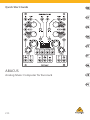 1
1
-
 2
2
-
 3
3
-
 4
4
-
 5
5
-
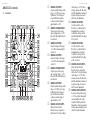 6
6
-
 7
7
-
 8
8
-
 9
9
-
 10
10
-
 11
11
-
 12
12
-
 13
13
-
 14
14
-
 15
15
-
 16
16
-
 17
17
-
 18
18
-
 19
19
-
 20
20
-
 21
21
-
 22
22
-
 23
23
-
 24
24
-
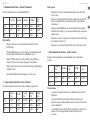 25
25
-
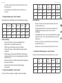 26
26
-
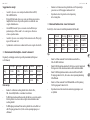 27
27
-
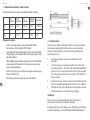 28
28
-
 29
29
-
 30
30
-
 31
31
-
 32
32
-
 33
33
-
 34
34
-
 35
35
-
 36
36
-
 37
37


Behringer ABACUS Skrócona instrukcja obsługi
- Typ
- Skrócona instrukcja obsługi
w innych językach
- español: Behringer ABACUS Guía de inicio rápido
- italiano: Behringer ABACUS Guida Rapida
- Deutsch: Behringer ABACUS Schnellstartanleitung
- português: Behringer ABACUS Guia rápido
- français: Behringer ABACUS Guide de démarrage rapide
- Nederlands: Behringer ABACUS Snelstartgids