
INSTALLATION & MAINTENANCE GUIDE
Help Hotline:
1-813-978-3900 • Mon-Fri 9am-6pm (EST)
www.amplighting.com
AMP
®
Low Voltage Landscape Lighting
AMP
®
ONE ControlPro
TM
200 LED Downlight
AAL-1813IR-40-BBZ

AMP
®
ONE ControlPro
TM
200 LED Downlight
AAL-1813IR-40-BBZ
Important Safety Instructions: Read Before Installation
INSTALLATION & MAINTENANCE GUIDE
!
www.amplighting.com
–2–
This luminaire is intended for installation in accordance with local codes
and the National Electric Code (NEC). Failure to adhere to these codes and
instructions may result in serious injury, property damage and void the
warranty.
These instructions do not intend to cover all variations in installation,
operation maintenance or mounting situations.
1. Make sure the power is turned OFF before installing or servicing this
luminaire.
2. WARNING: risk of electrical shock. Install all luminaires 10 feet (3.05M)
or more from pool, spa or fountain.
3. This luminaire is intended to be used only with a power supply
(transformer) rated maximum of 300 watts (25 AMPS) at 15 volts.
4. Wiring connections must be made with UL listed wire connectors that are
suitable for outdoor use.
5. Position the low voltage wire and wire connector so that it is located
within 6 inches (15.2 cm) from a building structure, a luminaire or
tting.
6. The main low voltage cable is intended for shallow burial - less than 6
inches (152 mm).
7. If additional lengths of low voltage cable are required, please contact
www.amplighting.com or call 1-813-978-3900.
Important Safety Instructions
!
INSTRUCTIONS PERTAINING TO A RISK OF FIRE, OR INJURY TO PERSONS
Lighted lamp is HOT!
WARNING – To reduce the risk of FIRE OR INJURY TO PERSONS.
1. Turn off/unplug and allow to cool before replacing lamp.
2. Lamp gets HOT quickly! Contact only switch/plug when turning on.
3. Do not touch the hot lens, guard or enclosure.
4. Keep lamp away from materials that may burn.
5. Do not touch lamp at any time. Use a soft cloth. Oil from skin may
damage lamp.
6. Do not operate the luminaire tting with a missing or damaged shield.
SAVE THESE INSTRUCTIONS

[email protected] • 813.978.3900
Parts Required (sold separately)
–3–
Package Contents
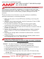
Install Fixture
1
A. (1) Fixture
B. (1) 35
0
Optic
A. (1) ONE Design-Master Remote Control
TM
Product Dimensions
4 1/8”
6 5/8”
4.68”
Determine the desired location
for the xture. Place the washers
onto the self-tapping screws. Pass
the self-tapping screws through
the holes of the feet of xture and
spacers. Thread the self-tapping
screws into the desired location to
secure the xture.
NOTE: Anchors are required for
brick walls or concrete walls. To
determine the locations for the
anchors place the feet of the xture
onto your desired location and mark
points from the holes of the feet.
Self-tapping Screw
(not supplied)
Washer (not supplied)
Anchor (optional,
not supplied)
Foot
Spacer
Fixture
* Ships with a 60°optic installed.

INSTALLATION & MAINTENANCE GUIDE
–4–
www.amplighting.com
–4–
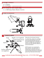
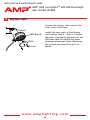
Wire Connections
2
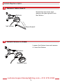
Adjust Glare Guard Direction
3
AMP
®
ONE ControlPro
TM
200 LED Downlight
AAL-1813IR-40-BBZ
Strip both leads from the
luminaire pigtail. Using
two wire connectors (sold
separately), connect the leads
from the luminaire to the
main supply cable leads.
Pigtail
Main Supply Cable
Wire Connectors
Unlock the knob and rotate
the glare guard to your desired
direction. Hand tighten
the knob once your desired
direction is achieved.
Glare Guard
Knob

[email protected] • 813.978.3900
–5–
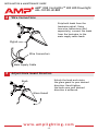
Install Fixture to Stake
5
Remove Glare Guard
4
Install/Replace Optic
Loosen the set screw and
remove the glare guard from
the xture.
Glare Guard
Set Screw
Fixture
Loosen the xture lens and remove
it from the xture.
Fixture Lens
Fixture

–6–
www.amplighting.com
–6–
INSTALLATION & MAINTENANCE GUIDE
AMP
®
ONE ControlPro
TM
200 LED Downlight
AAL-1813IR-40-BBZ
Replace Optic
6
Loosen the screws, and remove the
optic from the xture.
Install the new optic in the xture
and reverse Step 6 - Step 4. Conrm
the optic is properly aligned over the
LED board before tightening down.
Improper alignment when tightening
the screws can cause the optic to
break.
Screw
Optic
LED Board
Fixture


IS-AAL-1813IR-40-BBZ.ver1
Specications and product details subject to change without notice.
© Copyright 2019, AMP
®
Lighting, Lutz FL USA 33549 • All rights reserved.
[email protected] • 813.978.3900
Help Hotline:
1-813-978-3900 • Mon-Fri 9am-6pm (EST)
www.amplighting.com
-
 1
1
-
 2
2
-
 3
3
-
 4
4
-
 5
5
-
 6
6
-
 7
7
-
 8
8


AMP Lighting AAL-1813IR-40-BBZ-BUNDLE Instrukcja instalacji
- Typ
- Instrukcja instalacji
- Niniejsza instrukcja jest również odpowiednia dla
w innych językach
Powiązane artykuły
-
 AMP Lighting AAL-1022-B-BZ Instrukcja instalacji
-
 AMP Lighting AAL-30XXIR Series Installation & Maintenance Manual
-
 AMP Lighting AviatorPro Instrukcja instalacji
-
 AMP Lighting VAL-91 Series Installation & Maintenance Manual
-
 AMP Lighting MR16 HydraPro Installation & Maintenance Manual
-
 AMP Lighting AAL-1013-B-BZ-R1 Instrukcja instalacji
-
 AMP Lighting EscherPro AAL-1023 Series Installation & Maintenance Manual
-
 AMP Lighting AAL-1018 Instrukcja instalacji
-
 AMP Lighting AAL-1016-40-B-BZ-BUNDLE Instrukcja instalacji
-
 AMP Lighting ADL-2012-B-BZ Instrukcja instalacji


