Williams AX2 LED Series Instrukcja instalacji
- Typ
- Instrukcja instalacji

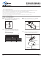
AX2 LED SERIES
INSTALLATION INSTRUCTIONS
H.E. Williams, Inc. Carthage, Missouri www.hew.com 417-358-4065
Page 1 of 3
PN 49090150
Warning:
Caution – Risk of Shock
• This product must be installed in accordance with the applicable installation code by a person familiar with the construction and operation of
the product and the hazards involved.
• LEDs are ESD (Electro Static Discharge) sensitive devices that can be easily damaged if the proper ESD mitigating steps are not taken.
• LEDs are very sensitive to mechanical damage. Caution must be taken to avoid damage to the LEDs.
• Do not use power tools to fasten the boards into the fixture. Over-torqueing the LED board fasteners will damage the boards.
• Make sure all electrical power is turned off while installing the fixture.
• This luminaire must be adequately grounded for protection against shock hazards and to assure proper operation.
• Disconnect power before servicing.
01/06/16JL
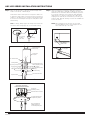
STAND-ALONE ASSEMBLY
Step 1: T-bar mounting bracket halves are supplied as a one-piece
metal stamping. Break mounting bracket apart. Insert 1/4-
20 threaded stud into “A” half of bracket (Fig. 1).
1/4-20
Stud
Insert stud here
Bracket side “A”
Fig. 1
Step 2: For T-bar ceiling, install mounting brackets at desired
locations. Brackets must be placed exactly on each
mounting point for correct installation and hanging of
cables.
MOUNTING INFORMATION
A
B
Nominal Unit Length Mounting Length (A) Actual Length (B)
2’ 24-5/8” 25-7/8”
4’ 46-13/16” 48-1/16”
8’ 89-7/8” 91-1/8”
Step 3: T-bar mounting bracket halves interlock. Snap side “B”
together with side “A” around T-bar. (Fig. 2).
T-bar ceiling grid
Insert tab
Bracket side “A”
Bracket halves lock together
with slots and tabs.
Bracket side “B”
Fig. 2
Step 4: Suspension locations must be securely supported to the
structure before hanging light fixtures onto brackets. Use
12-gauge or stronger steel ceiling support wire (Fig. 3).
Support to structure
T-bar
1/4-20 Stud
(locked into bracket)
T-bar mounting bracket
shown fully assembled
ø5” Canopy
Thread upper cable
retainer onto stud
Suspension Cable
Hole for power feed
Fig. 3

AX2 LED SERIES INSTALLATION INSTRUCTIONS
H.E. Williams, Inc. Carthage, Missouri www.hew.com 417-358-4065
Page 2 of 3
PN 49090150
Step 5: Place the canopy flush to ceiling tile and thread upper cable
retainer onto the 1/4 - 20 stud (Fig. 3).
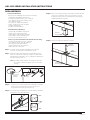
A stand-alone fixture will require two suspension cables. The
5” diameter canopy will be used only at power feed locations.
Smaller 2” canopies are to be used at non-feed locations (Fig.
4). Power feed cord will pass through hole with plastic strain
relief bushing.
Note: For safety, always support the weight of the fixture. Do
not leave a fixture hanging by only one end while working.
2” canopy
The 5” canopy
is used for
power feed.
Fig. 4
1/4 x 20 Screw or Bolt
To lighting panel via
existing circuitry
Mounting Bracket
T-bar (manuf. by others)
Suspension Cable
Junction box &
cover plate
2” threaded nipple with lock
washers (supplied by others)
Ceiling tile
(supplied by others)
ø5” canopy
Strain relief bushing
Power feed cord to fixture
Fig.5A
Typical power feed location
for sheetrock/hardpan installation
Junction box
(furnished by others)
5” canopy with center hole
and power entry location
Cross bar with 1/4” x 20 stud
Only 1/4-20 all thread
material needed for 2”
non-feed suspension point.
Step 6: Hang the fixture from suspension cables by hooking into
each end of light fixture. Install 10 - 32 flange nuts from the
hardware kit onto threaded cable end and adjust up or down
as necessary until fixture is level (Fig. 5A). Fully adjustable
cables allow you to vary the length from 6” to 96” with a
stopping device that may be secured at any point along the
length of cable. One 10 - 32 flange nut from the hardware kit
secures the fixture.
NOTE: When hanging the junction box onto the T-bar
mounting bracket, tie the ceiling support wire for
this location directly to the T-bar.
Stand off
Power location
Power
cord
Griplock side
exit gripper
Fig. 6
Fig.5B

AX2 LED SERIES INSTALLATION INSTRUCTIONS
H.E. Williams, Inc. Carthage, Missouri www.hew.com 417-358-4065
Page 3 of 3
PN 49090150
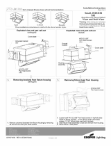
ROW ASSEMBLY
Power Feed Hardware:
Each power feed hardware kit includes the following:
(1) Assembly & Installation Instructions
(2) T-bar mounting brackets & 1/ 4” - 20 studs
(1) 5” diameter canopy with retaining screw
(1) 2” diameter canopy
(2) Suspension cables with hardware
(2) 10” - 32 flange nuts with serrations
(1) Strain relief bushing
(5) Cable ties (white plastic)
Joiner/End Fixture Hardware:
(1) Assembly & installation instructions
(1) AX2 center suspension bracket
(2) Row aligner channel/ AX2 (side btm)
(1) Row aligner channel/ AX2 (bottom)
(2) Screw, SS hex 1/4”x14 1” long
Each non-power feed hardware kit includes the following:
(1) T-bar mounting bracket & 1/ 4” - 20 stud
(1) 2” diameter canopy with 1/4” diameter
(1) Suspension cable with hardware
(1) 10 - 32 flange nuts with serrations
(1) #8 x 3/8” hex head screw
Step 1: For T-bar ceiling, install mounting brackets at desired
locations (see stand-alone assembly step 1 & 2).
Step 2: Install mounting cables at desired locations. Only the first
fixture in each row will require two suspension cables. Each
adjoining fixture will require only one cable before attaching to
the previous fixture. (Fig. 7).
Note: For safety - Always support the weight of the fixture.
Do not leave a fixture hanging by only one end while
working.
2” canopy
The 5” canopy
is used for
power feed.
Fig. 7
Step 3: To remove lens, insert a putty knife or flat blade screwdriver
between the lens and channel. Pry up to get the lens
loosened and then gently peel the lens up.
Step 4: For continuous row applications, use Row Aligners (installed
in fixtures) for level and adjustment.
Row aligner
Row
aligner
slot
AX2U
AX2D
Step 5: When row mounting fixtures, joint between fixtures will have
continuous row bracket. After connecting quick connects
and fixtures, add continuous row bracket around fixture by
snapping the bracket into place.
Continuous
row bracket
Step 6: Add center suspension bracket to fixtures..
Center
Suspension
Bracket
Continuous
row bracket
Suspension
Cable Mount
-
 1
1
-
 2
2
-
 3
3


Williams AX2 LED Series Instrukcja instalacji
- Typ
- Instrukcja instalacji
w innych językach
Powiązane artykuły
Inne dokumenty
-
ROOMS TO GO 90600682 Assembly Instructions
-
Minka Group 4716-892 Instrukcja obsługi
-
Lightolier 40600N2 Instrukcja obsługi
-
Elk Home 57027-4 Instrukcja instalacji
-
-
Aria W.C. Niche Instrukcja instalacji
-
-
 Ametrix SRI Instrukcja obsługi
-
 Blueprint Lighting Campana Instrukcja instalacji
-
Ametrix CPP/CPS Instrukcja obsługi

