
601CA
ISTRUZIONI PER L’USOI
INSTRUCTIONS FOR USEEN
MODE D’EMPLOIF
GEBRAUCHSANWEISUNGD
INSTRUCCIONESE
INSTRUÇÕES DE USOPT
GEBRUIKSAANWIJZINGNL
INSTRUKCJA OBSŁUGIPL
h
e
f
±
d
a
b
c
601CA.indd 1 08/09/16 10:54

2
ISTRUZIONI PER L’USO
I
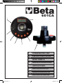
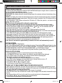
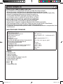
GONIOMETRO DIGITALE PER SERRAGGI COPPIA E ANGOLO ART. 601CA
MANUALE D’USO ED ISTRUZIONI PER IL GONIOMETRO DIGITALE PRODOTTO DA:
BETA UTENSILI S.P.A.
Via A. Volta 18,
20845, Sovico (MB)
ITALIA
Documentazione redatta originariamente in lingua ITALIANA.
Conservare accuratamente le istruzioni di sicurezza e consegnarle al personale utilizzatore.
DESTINAZIONE D’USO
Il goniometro digitale è destinato al seguente uso:
• misurazione della coppia o angolo di serraggio destrorso/sinistrorso su viti e dadi in abbinamento
a cricchetti o leve
Non sono consentite le seguenti operazioni:
• non utilizzare il goniometro digitale in ambienti umidi, bagnati. Non esporlo a calore, pioggia o neve
• non superare la capacità massima del goniometro
• è vietato il contatto del goniometro digitale con sostanze chimiche e corrosive
• è vietato l’uso per tutte quelle applicazioni diverse da quelle indicate
SICUREZZA DELLA POSTAZIONE DI LAVORO
Non utilizzare il goniometro digitale in ambienti contenenti atmosfere potenzialmente esplosive
perché possono svilupparsi scintille in grado di incendiare polveri o vapori.
Impedire che i bambini possano entrare in diretto contatto con il goniometro digitale.
Non utilizzare il goniometro digitale in prossimità di materiale inammabile. .
SICUREZZA GONIOMETRO DIGITALE
• Prima dell’utilizzo controllare che il goniometro digitale non abbia subito danneggiamenti e che non vi
siano parti usurate.
• Non manomettere il circuito elettronico del goniometro digitale.
INDICAZIONE PER LA SICUREZZA DEL PERSONALE
Si raccomanda la massima attenzione, avendo cura di concentrarsi sempre sulle proprie azioni. Non
utilizzare il goniometro digitale in caso di stanchezza o sotto l’effetto di droghe, bevande alcoliche o
medicinali.
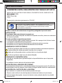
INSERIMENTO / SOSTITUZIONE DELLE BATTERIE
Per l’installazione o la sostituzione delle batterie procedere nel seguente modo.
• Allentare le quattro viti di chiusura vano batterie poste sul retro.
IMPORTANTE LEGGERE COMPLETAMENTE IL PRESENTE MANUALE
PRIMA DI UTILIZZARE IL GONIOMETRO DIGITALE. IN CASO DI MANCATO
RISPETTO DELLE NORME DI SICUREZZA E DELLE ISTRUZIONI OPERA-
TIVE, POSSONO VERIFICARSI SERI INFORTUNI.
ATTENZIONE
601CA.indd 2 08/09/16 10:54

3
ISTRUZIONI PER L’USO
I
• Rimuovere le batterie scariche, inserire le nuove batterie facendo attenzione alla polarità
(n° 2 batterie AAA).
• Chiudere il vano batterie serrando le quattro viti.
• Se si prevede un lungo periodo di inutilizzo rimuovere le batterie.
• In caso di batteria scarica, sul display appare il simbolo della batteria.
INDICAZIONI DI SICUREZZA DEL GONIOMETRO DIGITALE
• Evitare cadute o colpi al goniometro digitale.
• Non utilizzare il goniometro digitale in ambienti umidi o bagnati.
• Per la pulizia utilizzare un panno asciutto. Non utilizzare mai alcool o diluenti.
• Non avvicinare il goniometro digitale a campi magnetici.
• Il goniometro digitale non deve essere modicato. Le modiche possono comprometterne il corretto
funzionamento.
DATI TECNICI
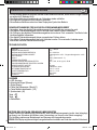
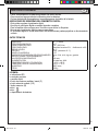
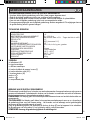
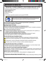
LEGENDA
a: indicatori LED
b: avvisatore acustico
c: display digitale
d: pulsante inizio misurazioni / menu (C)
e: pulsante selezione unità (U/S)
f: pulsante memoria (M)
pulsante +
pulsante -
h: vano batteria
DISPLAY
PRECISIONE ANGOLO
CAMPO MISURA COPPIA
PRECISIONE COPPIA
RISOLUZIONE
SCALA
ATTACCO QUADRO
UNITÀ DI MISURA SELEZIONABILI
SETTAGGI IMPOSTABILI
VALORI MEMORIZZATI
ALIMENTAZIONE
TEMPERATURA DI UTILIZZO
TEMPERATURA DI STOCCAGGIO
UMIDITÀ
PESO
0 ---> 999,0
± 2°
10 ÷ 200 N.m
Senso orario ±3% - Antiorario ±4%
0.1°
360° (incremento 0.1°)
1/2"
N.m, ft.lb, in.lb, kg.cm, gradi
9
50 max
2 batterie AAA
-10°C ÷ 60°C
-20°C ÷ 70°C
90% max
260 g
>
>
601CA.indd 3 08/09/16 10:54

4
FUNZIONAMENTO DEL GONIOMETRO DIGITALE
Questo strumento è studiato per misurare i valori di coppia di serraggio o angolari destrorsi/sinistrorsi su viti
e dadi in abbinamento a cricchetti o leve. Sono previste due modalità di misura della coppia di serraggio:
PICCO: il display mostra la coppia immediata di serraggio, mostrando alla ne il valore massimo raggiunto.
TRACCIA: il display mostra solo la coppia istantanea di serraggio ed alla ne della misurazione il
goniometro è pronto per una nuova misura. L’accensione dell’indicatore LED ed il segnale acustico
indicano il raggiungimento del valore impostato.
• Appoggiare il goniometro su una supercie piana e premere il pulsante (C) per l’accensione.
Sul display apparirà la visualizzazione del simbolo
0000
; attendere qualche secondo.
NOTA: Durante il settaggio non muovere il goniometro.
• A settaggio ultimato sul display apparirà la coppia o l’angolo precedentemente impostato.
• Premere il pulsante U/S per variare l’unità di misura della coppia o per selezionare il valore in gradi.
Impostare il nuovo valore di coppia o angolo con i pulsanti e . Il nuovo valore selezionato sarà
salvato automaticamente in memoria. Premere quindi il pulsante (M).
• Posizionare sul goniometro la bussola con il cricchetto. E’ possibile quindi iniziare il serraggio.
• L’accensione del primo LED verde ed il segnale acustico indicano il raggiungimento dell’80% del
valore selezionato.
• L’accensione del LED rosso indica il raggiungimento del valore massimo impostato.
• In modalità PICCO, premere il pulsante (M) per memorizzare la coppia o l’angolo di serraggio effettuato
(max 50 valori memorizzati). Sul display lampeggia il numero dove è stato memorizzato il valore.
ATTENZIONE. In modalità PICCO, se si interrompe il serraggio per alcuni secondi il display lampeggia
indicando il valore raggiunto al momento dell’interruzione. Riprendendo il serraggio il valore verrà cal-
colato a partire dal valore raggiunto precedentemente.
• Per azzerare la misurazione ed effettuarne una nuova premere il pulsante (C).
Dopo circa 2 minuti di inutilizzo il display si spegne automaticamente.
IMPOSTAZIONE MENU
Accendere il goniometro tramite il pulsante (C).
Tenere premuto il pulsante (U/S) per entrare nel menu di congurazione. Premendo il pulsante (U/S)
più volte si entrerà nei rispettivi menu: PICCO/TRACCIA, UNITÀ DI MISURA COPPIA E ANGOLI DI
SERRAGGIO, MEMORIE SERRAGGI, RESET MEMORIE SERRAGGI e CONTEGGIO SERRAGGI.
Per uscire dal menu di congurazione e tornare alle memorie preimpostate occorre premere ulterior-
mente il pulsante (U/S).
MENU PICCO/TRACCIA
• Durante il serraggio viene visualizzata la coppia immediata di serraggio
• Nella modalità PICCO, al momento del rilascio, viene visualizzato il valore massimo raggiunto.
• Nella modalità TRACCIA, al momento del rilascio, viene visualizzato il valore massimo preimpostato.
Il goniometro è pronto per un nuovo serraggio.
• La modalità TRACCIA non consente di memorizzare i valori raggiunti.
• In modalità PICCO il display visualizza ModE ed in basso a destra una P. Se il display è in modalità
TRACCIA mostra una T.
• Premere i pulsanti e per cambiare la modalità.
• Per uscire dal menu premere più volte il pulsante (U/S).
MENU UNITÀ DI MISURA COPPIA DI SERRAGGIO DURANTE LA MISURA DI ANGOLI
• Quando si effettuano misure angolari, il dispositivo misura anche la coppia di serraggio
contemporaneamente applicata.
• Al termine del serraggio, se si è in modalità PICCO, sul display appaiono alternativamente i valori della
coppia e dell’angolo.
• Questo menu consente di selezionare l’unità di misura della coppia.
ATTENZIONE.
Memorizzando il valore del dispositivo, viene registrato l’angolo ma non la rispettiva coppia.
• Il display mostra A-UI e sulla destra l’unità di misura attualmente selezionata.
• Premere i pulsanti e per cambiare l’unità di misura.
• Per uscire dal menu premere più volte il pulsante (U/S).
ISTRUZIONI PER L’USO
I
>
>>
>
> >
601CA.indd 4 08/09/16 10:54

5
MENU MEMORIE SERRAGGI
• Fornisce il valore di coppia di serraggio o angolo misurati e memorizzati (max 50 valori memorizzati).
• Se non vi sono valori memorizzati nel menu, il display mostra nonE.
• Il display mostra per ogni area di memoria il valore di serraggio memorizzato (n005 ˂--˂ 20.3°).
• Preme i pulsanti e per selezionare i valori memorizzati.
• Per cancellare uno dei valori memorizzati posizionarsi sull’area di memoria e premere due volte il pulsante (C).
• Per uscire dal menu premere più volte il pulsante (U/S).
MENU RESET MEMORIE SERRAGGI
• Permette di cancellare tutti i valori memorizzati nel menu MEMORIE SERRAGGI.
• Il display mostra ClrA
• Per cancellare tutti i valori memorizzati premere il pulsante (C): il display mostra no?
• Per cancellare tutte le memorie premere di nuovo il pulsante (C). Per annullare l’operazione premere
il pulsante (U/S).
• Per uscire dal menu premere più volte il pulsante (U/S).
MENU CONTEGGIO SERRAGGI
• Il dispositivo memorizza i serraggi effettuati ad un valore di coppia pari o superiori al 60% della capacità
massima dello strumento.
• Il conteggio non è azzerabile no alla successiva taratura.
• Ad esempio, se il display mostra (n-0 <--> 0160) signica che sono stati effettuati 160 serraggi.
Se l’indicazione è (n-1 <--> 2500) i serraggi effettuati sono stati 12.500.
• Per uscire dal menu premere due volte il pulsante (U/S).
MESSAGGI DI ERRORE
• Er0 > il goniometro è stato sottoposto ad una coppia di serraggio superiore al 110% del valore massimo.
• Er4 > il settaggio non è avvenuto correttamente. Premere il pulsante (C) per ripetere l’operazione.
Non muovere il goniometro durante il settaggio.
• Er5 > il goniometro non funziona correttamente. Effettuare l’operazione di RESET.
• Er---> il goniometro è stato ruotato troppo velocemente durante una misurazione. Premere il pulsante
(C) per ripetere l’operazione.
• Full > Non è possibile registrare dati in memoria perchè la memoria è piena. Cancellare alcuni dei
50 dati in memoria.
RESET
• E’ possibile l’azzeramento del goniometro rimuovendo le batterie.
MANUTENZIONE
Gli interventi di manutenzione, riparazione ed eventuale calibrazione devono essere eseguiti da perso-
nale specializzato. Per tali interventi potete rivolgervi al centro riparazioni di Beta Utensili S.P.A.
SMALTIMENTO
Il simbolo del cassonetto barrato riportato sull’apparecchiatura o sulla confezione indica che il prodotto,
alla ne della sua vita utile, deve essere smaltito separatamente dagli altri riuti urbani.
L’utilizzatore che intendesse smaltire questo strumento può:
• consegnarlo presso un centro di raccolta di riuti elettronici od elettrotecnici;
• riconsegnarlo al proprio rivenditore al momento dell’acquisto di uno strumento equivalente;
• nel caso di prodotti ad uso esclusivo professionale, contattare il produttore che dovrà disporre una
procedura per il corretto smaltimento.
Il corretto smaltimento di questo prodotto permette il riutilizzo delle materie prime in esso contenute ed
evita danni all’ambiente ed alla salute umana.
Lo smaltimento abusivo del prodotto costituisce una violazione della norma sullo smaltimento di riuti
pericolosi e comporta l’applicazione delle sanzioni previste.
ISTRUZIONI PER L’USO
I
>
>
601CA.indd 5 08/09/16 10:54

6
ISTRUZIONI PER L’USO
I
GARANZIA
DICHIARAZIONE DI CONFORMITÀ UE
Questo goniometro digitale è fabbricato e collaudato secondo le norme attualmente vigenti nella
Comunità Europea. E’ coperta da garanzia per un periodo di 12 mesi per uso professionale o 24 mesi
per uso non professionale.
Vengono riparati guasti dovuti a difetti di materiale o di produzione, mediante ripristino o sostituzione
dei pezzi difettosi a nostra discrezione.
L’effettuazione di uno o più interventi nel periodo di garanzia non modica la data di scadenza della stessa.
Non sono soggetti a garanzia difetti dovuti all’usura, all’uso errato od improprio e a rotture causate da
colpi e/o cadute.
La garanzia decade quando vengono apportate modiche, quando il goniometro digitale viene mano-
messo o quando viene inviato all’assistenza smontato.
Sono espressamente esclusi danni causati a persone e/o cose di qualsiasi genere e/o natura, diretti
e/o indiretti.
Dichiariamo sotto la nostra responsabilità che il prodotto descritto è conforme alle disposizioni pertinenti
alle seguenti Direttive:
• Direttiva Compatibilità Elettromagnetica (E.M.C.) 2014/30/UE
• Direttiva sulla restrizione dell’uso di determinate sostanze pericolose nelle apparecchiature elettriche
ed elettroniche (Ro.H.S.) 2011/65/UE
Il Fascicolo Tecnico è disponibile presso:
BETA UTENSILI S.P.A.
Via A. Volta 18,
20845 Sovico (MB)
ITALIA
601CA.indd 6 08/09/16 10:54

7
ISTRUZIONI PER L’USO
I
INSTRUCTIONS FOR USE
EN
DIGITAL TORQUE AND ANGLE GAUGE ITEM 601CA
OPERATION MANUAL AND INSTRUCTIONS FOR THE DIGITAL ANGLE GAUGE MANUFACTURED BY:
BETA UTENSILI S.P.A.
Via A. Volta 18,
20845, Sovico (MB)
ITALY
Original documentation drawn up in ITALIAN.
Store the safety instructions with care and hand them over to the users.
PURPOSE OF USE
The digital gauge can be used for the following purpose:
• measuring the right-hand/left-hand torque or angle on screws and nuts in combination with ratchets
or levers.
The following operations are not permitted:
• the digital gauge must not be used in humid or wet environments, and must not be exposed to heat,
rain or snow
• the maximum capacity of the gauge must not be exceeded
• the digital gauge must not come into contact with chemical and corrosive substances
• the digital gauge must not be used for any applications other than recommended ones.
WORK AREA SAFETY
Do not operate the digital gauge in environments containing potentially explosive atmospheres,
because sparks may be generated, which can ignite the dust or fumes.
Keep children away from the digital gauge.
Do not use the digital gauge near ammable material. .
DIGITAL GAUGE SAFETY
• Before use, check that the digital gauge has not been damaged, and that no parts are worn.
• Do not force the electronic circuit of the digital gauge.
PERSONNEL SAFETY
Stay alert; watch what you are doing. Do not use the digital gauge while tired or under the inuence of
drugs, alcohol, or medication.
BATTERY INSTALLATION/REPLACEMENT
Install or replace the batteries as follows.
• Loosen the four screws of the battery compartment on the back.
IMPORTANT! READ THIS MANUAL THOROUGHLY BEFORE USING THE
DIGITAL GAUGE. FAILURE TO COMPLY WITH THE SAFETY STANDARDS
AND OPERATING INSTRUCTIONS MAY RESULT IN SERIOUS INJURY.
CAUTION
601CA.indd 7 08/09/16 10:54

8
ISTRUZIONI PER L’USO
I
INSTRUCTIONS FOR USE
EN
• Remove the at batteries, and install the new batteries, paying attention to the polarity (2 AAA batteries).
• Close the battery compartment, and tighten the four screws.
• Remove the batteries, if the digital gauge is not used for an extended period.
• If the battery is at, the battery symbol will be shown on the display.
DIGITAL GAUGE SAFETY
• Do not drop or hit the digital gauge.
• Do not use the digital gauge in humid or wet environments.
• To clean the digital gauge, use a dry cloth. Do not use alcohol or diluents.
• Do not place the digital gauge near magnetic elds.
• Do not modify the digital gauge. Changes may affect operation.
TECHNICAL DATA
KEY TO SYMBOLS
a: LED indicators
b: buzzer
c: digital display
d: start of measurement / menu button (C)
e: unit selection button (U/S)
f: pulsante memoria (M)
f: memory button (M)
+ button
- button
h: battery compartment
DISPLAY
PRECISIONE ANGOLO
TORQUE MEASURING RANGETORQUE
ACCURACY
RESOLUTION
SCALE
SQUARE DRIVE
SELECTABLE UNITS OF MEASUREMENT
PROGRAMMABLE VALUES
STORED VALUES
POWER SUPPLY
OPERATING TEMPERATURE
STORAGE TEMPERATURE
HUMIDITY
WEIGHT
0 ---> 999,0
± 2°
10 ÷ 200 N.m
Clockwise ±3% - Anticlockwise ±4%
0.1°
360° (increment 0.1°)
1/2"
N.m, ft.lb, in.lb, kg.cm, gradi
9
50 max
2 AAA batteries
-10°C ÷ 60°C
-20°C ÷ 70°C
max 90%
260 g
>
>
601CA.indd 8 08/09/16 10:54

9
ISTRUZIONI PER L’USO
I
INSTRUCTIONS FOR USE
EN
DIGITAL GAUGE OPERATION
This device has been designed to measure right-hand/left-hand torque or angle values on screws and
nuts in combination with ratchets or levers.
Two driving torque measurement modes are available:
PEAK HOLD: the display shows the instant driving torque, the maximum achieved value being shown
at the end.
TRACK: the display only shows the instant driving torque; after the measurement has been completed,
the gauge is ready for a new measurement. When the set value is reached, the LED indicator will turn
on and the buzzer will sound.
• Lay the gauge on a at surface and press the ON button (C). When the symbol
0000
is shown on the
display, wait a few seconds.
NB: Do not move the gauge while setting the required value.
• After the required value has been set, the display will show the previously set torque or angle.
• Press button U/S to change the unit of measurement of the torque or select the value in degrees.
Set the new torque or angle value by pressing buttons and . The new selected value will
automatically be saved. Then press button (M).
• Place the socket with the ratchet on the gauge. Tightening can then be started.
• When 80% of the selected value is reached, the rst green LED will turn on and the buzzer will sound.
• When the maximum set value is reached, the red LED will turn on.
• In the PEAK HOLD mode, press button (M) to store the value of the driving torque or angle
(max. stored values: 50). The number where the value has been stored will blink on the display.
CAUTION: In the PEAK HOLD mode, if the tightening process is interrupted for a few seconds, the
display will blink, showing the value reached upon interruption. When the tightening process is
resumed, the value will be calculated from the value reached before.
• To reset the device and start a new measurement, press button (C).
If the device is not used for approximately 2 minutes, the device will automatically turn off.
SETTING UP MENU
Press button (C) to turn the gauge on.
Keep button (U/S) pressed to enter the conguration menu. Press button (U/S) several times to enter
the menus: PEAK HOLD/TRACK, UNITS OF MEASUREMENT OF DRIVING TORQUE AND ANGLES,
TORQUE MEMORIES, RESETTING TORQUE MEMORIES and TIGHTENING COUNT.
To quit the conguration menu and go back to the preset memories, press button (U/S) again.
PEAK HOLD/TRACK MENU
• During the tightening process, the instant driving torque will be displayed.
• In the PEAK HOLD mode, upon release, the maximum reached value will be displayed.
• In the TRACK mode, upon release, the maximum preset value will be displayed.
The gauge is ready for a new tightening process.
• The TRACK mode does not allow the reached values to be stored.
• In the PEAK mode, the display will show ModE and, in the right bottom corner, a P.
If the display is in the TRACK mode, it will show a T.
• Press buttons and to change the mode.
• To quit the menu, press button (U/S) several times.
TORQUE UNIT OF MEASUREMENT MENU FOR MEASURING ANGLES
• When angles are measured, the device will also measure the simultaneously applied driving torque.
• When the tightening process has been completed, if the device is in the PEAK HOLD mode, the torque
and angle values will be displayed alternatively.
• This menu allows the unit of measurement of the torque to be selected.
CAUTION: When the value of the device is saved, only the angle will be recorded, whereas the torque
will not.
• The display will show A-UI and, on the right, the currently selected unit of measurement.
• Press buttons and to change the unit of measurement.
• To quit the menu, press button (U/S) several times.
>
>
>
>
>
>
601CA.indd 9 08/09/16 10:54

10
ISTRUZIONI PER L’USO
I
INSTRUCTIONS FOR USE
EN
TORQUE MEMORIES MENU
• This menu provides the values of the measured and stored torque or angle (up to 50 values stored).
• If no values have been stored in the menu, the display will show nonE.
• The display will show the stored torque value for each memory area (n005<--> 20.3°).
• Press buttons and to select the stored values.
• To delete one of the stored values, press button (C) twice in the memory area.
• To quit the menu, press button (U/S) several times.
RESETTING TORQUE MEMORIES MENU
• This function allows all the values stored in the TORQUE MEMORIES menu to be deleted.
• The display will show ClrA
• To delete all the stored values, press button (C): the display will show no?
• To delete all the stored values, press button (C) again. To cancel the operation, press button (U/S).
• To quit the menu, press button (U/S) several times.
TIGHTENING COUNT MENU
• The device will store the torque at a torque value equal to, or higher than, 60% of its maximum capacity.
• The count cannot be reset until the next calibration.
• For example, if the display shows
(n-0 <--> 0160) , it means that 160 torque values have been set.
If it shows (n-1 <--> 2500), it means that 12,500 torque values have been set.
• To quit the menu, press button (U/S) twice.
ERROR MESSAGES
• Er0 > indicates that the gauge has been subjected to a driving torque higher than 110% of the maximum
value.
• Er4 > indicates that the value has not been set correctly. Press button (C) to repeat the operation.
Do not move the gauge while setting it.
• Er5 > indicates that the gauge is not working correctly. Proceed with the RESET.
• Er---> indicates that the gauge was rotated too quickly during a measurement. Press button (C) to repeat
the operation.
• Full > indicates that no data can be stored in the memory because the memory is full. Delete some
of the 50 stored data.
RESET
• The gauge can be reset by removing the batteries.
MAINTENANCE
Maintenance, repair and calibration jobs must be carried out by trained personnel only. For such jobs,
you can contact Beta Utensili S.P.A.’ s repair centre.
DISPOSAL
The crossed-out wheelie bin symbol on the equipment or packaging means that the product should be
collected separately from other types of urban waste at the end of its useful life.
Any user who is going to dispose of this tool can:
• deliver it to an appropriate collection facility for electronic and electrotechnical equipment;
• return it to the dealer upon purchase of a new, equivalent item of equipment;
• in case of a product for professional use only, contact the manufacturer which will arrange for the
product to be properly disposed of.
Proper disposal of this product allows the raw materials contained in it to be reused and prevents da-
mage to the environment and human health.
Illegal disposal of this product is a violation of the provision concerning the disposal of hazardous waste
and will give way to the application of such nes as provided for under current regulations.
>
>
601CA.indd 10 08/09/16 10:54

11
ISTRUZIONI PER L’USO
I
INSTRUCTIONS FOR USE
EN
WARRANTY
DECLARATION OF CONFORMITY EU
This digital gauge is manufactured and tested in accordance with current EU regulations. It is covered
by a 12-month warranty for professional use or a 24-month warranty for nonprofessional use.
We will repair any breakdowns caused by material or manufacturing defects by xing the defective
pieces or replacing them at our discretion.
Should assistance be required once or several times during the warranty period, the expiry date of this
warranty will remain unchanged.
This warranty will not cover defects due to wear, misuse or breakdowns caused by blows and/or falls.
In addition, this warranty will no longer be valid if any changes are made, or if the digital gauge is
forced or sent to the customer service in pieces.
This warranty explicitly excludes any damage to people and/or things, whether direct or consequential.
We hereby declare, assuming responsibility, that the described product complies with the relevant
provisions of the following Directives:
• Electromagnetic Compatibility Directive (EMC) 2014/30/EU;
• Directive concerning the restriction of the use of certain hazardous substances in electric and
electronic equipment (RoHS) 2011/65/EU.
The Technical Brochure is available at:
BETA UTENSILI S.P.A.
Via A. Volta 18,
20845 Sovico (MB)
ITALY
601CA.indd 11 08/09/16 10:54

12
MODE D’EMPLOI
F
RAPPORTEUR NUMÉRIQUE POUR SERRAGES COUPLE ET ANGULAIRES ART. 601CA
NOTICE D’UTILISATION ET INSTRUCTIONS POUR LE RAPPORTEUR NUMÉRIQUE FABRIQUÉ PAR:
BETA UTENSILI S.P.A.
Via A. Volta 18,
20845, Sovico (MB)
ITALIE
Documentation rédigée à l'origine en langue ITALIENNE.
Conserver soigneusement les instructions de sécurité et les remettre au personnel utilisateur.
DESTINATION D'UTILISATION
Le rapporteur numérique est destiné à l'utilisation suivante :
• mesure du couple ou angulaire de serrage droite/gauche sur vis et écrous associés à des cliquets ou leviers.
Les opérations suivantes ne sont pas autorisées:
• ne pas utiliser le rapporteur numérique dans des milieux humides ou mouillés.
Ne pas l'exposer à la chaleur, à la pluie ou à la neige;
• ne pas dépasser la capacité maximum du rapporteur ;
• ne pas mettre le rapporteur numérique en contact avec des substances chimiques et corrosives;
• ne pas l'utiliser pour toutes les applications non envisagées dans les présentes instructions.
SÉCURITÉ DU POSTE DE TRAVAIL
Ne pas utiliser le rapporteur numérique dans des milieux contenant des atmosphères
potentiellement explosives car des étincelles peuvent donner feu aux poussières ou aux vapeurs.
Faire en sorte que les enfants ne puissent pas se trouver en contact direct avec
le rapporteur numérique.
Ne pas utiliser le rapporteur numérique à proximité de matériel inammable.
SÉCURITÉ DU RAPPORTEUR NUMÉRIQUE
• Avant l'utilisation, contrôler que le rapporteur numérique n'ait pas subi de dommages et qu'il ne
présente pas de pièces usées.
• Ne pas intervenir sur le circuit électrique du rapporteur numérique.
INDICATION POUR LA SÉCURITÉ DU PERSONNEL
• Nous recommandons la plus grande attention en ayant soin de se concentrer constamment sur ses
propres actions. Ne pas utiliser le rapporteur numérique en cas de fatigue ou sous l’effet de drogues,
de boissons alcoolisées ou de médicaments.
INDICATION POUR LA SÉCURITÉ DU PERSONNEL
• Nous recommandons la plus grande attention en ayant soin de se concentrer constamment sur ses
propres actions. Ne pas utiliser le rapporteur numérique en cas de fatigue ou sous l’effet de drogues,
de boissons alcoolisées ou de médicaments.
IL EST IMPORTANT DE LIRE COMPLÈTEMENT LE PRÉSENT MANUEL
AVANT D'UTILISER LE RAPPORTEUR NUMÉRIQUE. EN CAS DE NON-
RESPECT DES NORMES DE SÉCURITÉ ET DES INSTRUCTIONS POUR LE
FONCTIONNEMENT, DE SÉRIEUX ACCIDENTS PEUVENT SE PRODUIRE.
ATTENTION
601CA.indd 12 08/09/16 10:54

13
MODE D’EMPLOI
F
INSTALLATION / REMPLACEMENT DES PILES
Pour l'installation ou le remplacement des piles, procéder de la façon suivante:
• dévisser les quatre vis de fermeture du compartiment des piles situé sur l'arrière;
• ôter les piles usées, introduire les nouvelles piles en faisant attention à la polarité (2 piles AAA);
• refermer le compartiment des piles en revissant les quatre vis ;
• si une période d'inutilisation prolongée est prévue, ôter les piles ;
• en cas de piles usées, le symbole de la pile s'afche sur l'écran.
INDICATIONS DE SÉCURITÉ DU RAPPORTEUR NUMÉRIQUE
• Éviter de faire tomber ou de heurter le rapporteur numérique;
• Ne pas utiliser le rapporteur numérique dans des milieux mouillés ou humides;
• Pour le nettoyage, utiliser un chiffon sec. N'utiliser en aucun cas de l'alcool ou des diluants;
• Ne pas approcher le rapporteur numérique à des champs magnétiques ;
• Le rapporteur numérique ne doit pas être modié. Les modications peuvent en compromettre le bon
fonctionnement.
CARACTÉRISTIQUES TECHNIQUES
LEGENDA
a: indicateurs LED
b: signal acoustique
c: afcheur numérique
d: touche de début de mesure / menu (C)
e: touche sélection unité (U/S)
f: touche mémoire (M)
touche +
touche -
h: compartiment piles
ÉCRAN
PRÉCISION ANGLE
CHAMP MESURE COUPLE
PRÉCISION COUPLE
RÉSOLUTION
ÉCHELLE
CARDAN CARRÉ
UNITÉS DE MESURE SÉLECTIONNABLES
RÉGLAGES PROGRAMMABLES
VALEURS MÉMORISÉES
ALIMENTATION
TEMPÉRATURE DE FONCTIONNEMENT
TEMPÉRATURE DE STOCKAGE
HUMIDITÉ
POIDS
0 ---> 999,0
± 2°
10 ÷ 200 N.m
Sens horaire ± 3% - Antihoraire ±4%
0.1°
360° (augmentation 0.1°)
1/2"
N.m, ft.lb, in.lb, kg.cm, gradi
9
50 max
2 piles AAA
-10°C ÷ 60°C
-20°C ÷ 70°C
90% max
260 g
>
>
601CA.indd 13 08/09/16 10:54

14
MODE D’EMPLOI
F
FONCTIONNEMENT DU RAPPORTEUR NUMÉRIQUE
Cet instrument est étudié pour mesurer les valeurs de couple de serrage ou angulaires droite/gauche
sur vis et écrous associés à des cliquets ou leviers.
Deux modalités de mesure du couple de serrage sont envisagées :
PIC: l'écran montre le couple immédiat de serrage, en montrant à la n la valeur maximum atteinte.
TRACE: l'écran montre uniquement le couple instantané de serrage et à la n du mesurage, le rappor-
teur est prêt pour une nouvelle mesure. L’éclairage de l’indicateur LED et le signal acoustique indiquent
que la valeur réglée est atteinte.
• Poser le rapporteur sur une surface plate et appuyer sur la touche (C) pour la mise en marche. L'écran
afchera le symbole
0000
; attendre quelques secondes.
NOTE: Pendant le réglage, ne pas faire bouger le rapporteur.
• À la n du réglage, l'écran afchera le couple ou l'angle précédemment programmé.
• Appuyer sur la touche U/S pour changer l'unité de mesure du couple ou pour sélectionner la valeur en
degrés. Programmer la nouvelle valeur de couple ou angulaire à l'aide des touches et . La nouvelle
valeur sélectionnée sera automatiquement sauvegardée en mémoire. Puis appuyer sur la touche (M).
• Positionner la douille avec le cliquet sur le rapporteur. Il est maintenant possible de commencer le serrage.
• L'éclairage de la première LED verte et le signal acoustique indiquent que la valeur sélectionnée est
atteinte à 80%.
• L'éclairage de la LED rouge indique que la valeur maximum programmée est atteinte.
• En modalité PIC, appuyer sur la touche (M) pour mémoriser le couple ou l'angle de serrage effectué
(max. 50 valeurs mémorisées). Sur l'écran clignote le numéro où a été mémorisée la valeur.
ATTENTION! En modalité PIC, si le serrage s'interrompt pendant quelques secondes, l'écran clignote
en indiquant la valeur atteinte au moment de l'interruption. En reprenant le serrage, la valeur sera cal-
culée à partir de la valeur atteinte précédemment.
• Pour mettre le mesurage à zéro et en effectuer un nouveau, appuyer sur la touche (C).
Après environ 2 minutes d'inutilisation, l'écran s'éteint automatiquement.
PROGRAMMATION MENU
Mettre le rapporteur en marche par le biais de la touche (C).
Appuyer longuement sur la touche (U/S) pour entrer dans le menu de conguration. En appuyant plu-
sieurs fois sur la touche (U/S), on accèdera aux menus respectifs : PIC/TRACE, UNITÉS DE MESURE
COUPLE ET ANGULAIRES DE SERRAGE, MÉMOIRES SERRAGES, RESET MÉMOIRES SERRA-
GES et COMPTAGE SERRAGES.
Pour sortir du menu de conguration et retourner aux mémoires préalablement programmées, appuyer
à nouveau sur la touche (U/S).
MENU PIC/TRACE
• Pendant le serrage, le couple immédiat de serrage est afché.
• Dans la modalité PIC, au moment du relâchement, la valeur maximum atteinte est afchée.
• Dans la modalité TRACE, au moment du relâchement, la valeur maximum programmée est afchée.
Le rapporteur est prêt à un nouveau serrage.
• La modalité TRACE ne permet pas de mémoriser les valeurs atteintes.
• En modalité PIC l'écran afche ModE et en bas à droite un P. Si l'écran est en modalité TRACE,
il afche un T.
• Appuyer sur les touches et pour changer de modalité.
• Pour sortir du menu, appuyer plusieurs fois sur la touche (U/S).
MENU UNITÉS DE MESURE COUPLE DE SERRAGE PENDANT LE MESURAGE DES ANGLES
• Lorsque l'on effectue la mesure des angles, le dispositif mesure également le couple de serrage
simultanément appliqué.
• À la n du serrage, en modalité PIC, l'écran afche alternativement les valeurs du couple et de l'angle.
• Ce menu permet de sélectionner l’unité de mesure du couple.
ATTENTION! En mémorisant la valeur du dispositif, l'angle est enregistré mais pas le couple
correspondant.
• L'écran afche A-UI et sur la droite l’unité de mesure sélectionnée à un moment précis.
• Appuyer sur les touches et pour changer d'unité de mesure.
• Pour sortir du menu, appuyer plusieurs fois sur la touche (U/S).
>
>
>
>
>
>
601CA.indd 14 08/09/16 10:54

15
MODE D’EMPLOI
F
MENU MÉMOIRES SERRAGES
• Il fournit la valeur de couple de serrage ou angulaire mesurée et mémorisée (max. 50 valeurs mémorisées).
• Si aucune valeur n'est mémorisée dans le menu, l'écran afche nonE.
• L'écran afche, pour chaque secteur de mémoire, la valeur de serrage mémorisée (n005 <--> 20.3°).
• Appuyer sur les touches et pour sélectionner les valeurs mémorisées.
• Pour effacer l'une des valeurs mémorisées, se placer sur la zone mémoire et appuyer deux fois sur
la touche (C).
• Pour sortir du menu, appuyer plusieurs fois sur la touche (U/S).
MENU RESET DES MÉMOIRES DE SERRAGE
• Il permet d'effacer toutes les valeurs mémorisées dans le menu MÉMOIRES SERRAGES.
• L'écran afche ClrA.
• Pour effacer toutes les valeurs mémorisées, appuyer sur la touche (C): l'écran afche no?
• Pour effacer toutes les mémoires, appuyer à nouveau sur la touche (C). Pour annuler l'opération,
appuyer sur la touche (U/S).
• Pour sortir du menu, appuyer plusieurs fois sur la touche (U/S).
MENU COMPTEUR DE SERRAGES
• Le dispositif mémorise les serrages effectués à une valeur de couple égale ou supérieure à
60 % de la capacité maximum de l'instrument.
• Le compteur ne peut pas être remis à zéro jusqu'au prochain étalonnage.
• Par exemple, si l'écran afche (n-0 <--> 0160), cela signie que 160 serrages ont été effectués.
Si l’indication est (n-1 <--> 2500), les serrages effectués sont au nombre de 12.500.
• Pour sortir du menu, appuyer deux fois sur la touche (U/S).
MESSAGES D'ERREUR
• Er0 > le rapporteur a été soumis à un couple de serrage supérieur à 110 % de la valeur maximum.
• Er4 > le réglage n'a pas été fait correctement. Appuyer sur la touche (C) pour renouveler l'opération.
Ne pas faire bouger le rapporteur pendant le réglage.
• Er5 > le rapporteur ne fonctionne pas correctement. Effectuer l'opération de RESET.
• Er---> le rapporteur a été tourné trop rapidement pendant un mesurage. Appuyer sur la touche (C)
pour renouveler l'opération.
• Full > Il n'est pas possible d'enregistrer les données en mémoire car la mémoire est pleine.
Effacer quelques unes des 50 données en mémoire.
RESET
• Il est possible de mettre le rapporteur à zéro en enlevant les piles.
MAINTENANCE
Les interventions de maintenance, de réparation et éventuellement d'étalonnage doivent être effectuées par un
personnel qualié. Pour ce type d'interventions, adressez-vous au centre de réparations de Beta Utensili S.P.A.
ÉCOULEMENT
Le symbole du bac barré reporté sur l'appareil ou sur l'emballage indique que le produit, à la n de sa
durée de vie, doit être écoulé séparément des autres déchets urbains.
L’utilisateur qui doit écouler cet instrument peut:
• le remettre à un centre de collecte de déchets électroniques ou électrotechniques;
• le retourner au vendeur au moment de l'achat d'un instrument équivalent;
• en cas de produit à usage professionnel exclusif, contacter le producteur qui devra disposer d'une
procédure pour l'écoulement correct.
L'écoulement correct de ce produit permet la réutilisation des matières premières qui le composent et
évite les dommages à l'environnement et à la santé humaine.
L'écoulement illégal du produit représente une violation de la norme sur l'écoulement des déchets
dangereux et comporte l'application des sanctions prévues.
>
>
601CA.indd 15 08/09/16 10:54

16
MODE D’EMPLOI
F
GARANTIE
DÉCLARATION DE CONFORMITÉ UE
Ce rapporteur numérique est fabriqué et testé selon les normes actuellement en vigueur dans l'Union
Européenne. Il est couvert par une garantie de 12 mois pour utilisation professionnelle ou de 24 mois
pour une utilisation non professionnelle.
Toutes les pannes dues à un défaut matériel ou de production seront réparées, en ajustant ou en
remplaçant les pièces défectueuses à notre discrétion.
La réalisation d’une ou de plusieurs interventions pendant la période de garantie n’en modie pas la
date d’échéance.
La garantie ne couvre pas les problèmes dus à l’usure des composants, à un usage erroné ou incor-
rect de l’outil, aux ruptures causées pas des coups et/ou des chutes.
La garantie ne s’appliquera pas en cas de modications ou d’altérations du rapporteur numérique ou
bien si celui-ci est envoyé à l’assistance technique démonté.
Tous les dommages causés aux personnes et/ou aux biens, directs et/ou indirects et de quelque
genre ou nature que ce soit, sont exclus de la garantie.
Nous déclarons sous notre responsabilité que le produit est conforme à toutes les dispositions perti-
nentes aux Directives suivantes :
• Directive Compatibilité Électromagnétique (E.M.C.) 2014/30/UE
• Directive sur la restriction de l'emploi de certaines substances dangereuses dans les appareils
électriques et électroniques (Ro.H.S.) 2011/65/UE
Le Fascicule Technique est disponible chez:
BETA UTENSILI S.P.A.
Via A. Volta 18,
20845 Sovico (MB)
ITALIE
601CA.indd 16 08/09/16 10:54

17
ISTRUZIONI PER L’USO
I
GEBRAUCHSANWEISUNG
D
DIGITALES DREHMOMENT- UND DREHWINKELMESSGERÄT ART. 601CA
GEBRAUCHSANWEISUNG FÜR DAS DIGITALE DREHWINKELMESSGERÄT HERGESTELLT VON:
BETA UTENSILI S.P.A.
Via A. Volta 18,
20845, Sovico (MB)
ITALIEN
Dokumentation Original in ITALIENISCHER SPRACHE verfasst.
Die Sicherheitsanweisungen sorgfältig aufbewahren und dem Bedienerpersonal übergeben.
BESTIMMUNGSZWECK
Das digitale Drehwinkelmessgerät ist für den folgenden Gebrauch bestimmt:
• Messung des rechts- und linksgängigen Anzugsdrehmoments oder Anzugswinkels von Schrauben
und Muttern unter Verwendung von Knarren oder Hebeln
Nicht zulässig sind die folgenden Arbeitsvorgänge:
• Nicht zu verwenden ist der Gebrauch des digitalen Drehwinkelmessgerätes in feuchten oder nassen
Räumen. Weder Hitze, Regen oder Schnee aussetzen
• Nicht die max. Kapazität des Drehwinkelmessgeräts überschreiten
• Unzulässig ist die Berührung des digitalen Drehwinkelmessgerätes mit chemischen oder korrosiven Stoffen
• Unzulässig ist der Gebrauch für andere Anwendungen als hier angegeben.
SICHERHEIT DES ARBEITSPLATZES
Das digitale Drehwinkelmessgerät nicht in explosionsfähiger Umgebung verwenden,
da sich Funken entwickeln können, die Staub oder Dämpfe entammen können.
Dafür sorgen, dass Kinder nicht in Berührung mit dem digitalen Drehwinkelmessgerät kommen können.
Das digitale Drehwinkelmessgerät nicht in der Nähe von entzündlichem Material verwenden.
BETRIEB DES DIGITALEN DREHWINKELMESSGERÄTES
• Vor dem Gebrauch überprüfen, dass das digitale Drehwinkelmessgerät nicht beschädigt oder
verschlissen ist.
• Den elektronischen Schaltkreis des digitalen Drehwinkelmessgerätes nicht beschädigen
HINWEISE FÜR DIE SICHERHEIT DES PERSONALS
Bei der Arbeit mit dem digitalen Drehwinkelmessgerät ist stets mit höchster Vorsicht vorzugehen. Auf
keinen Fall mit dem digitalen Drehwinkelmessgerät arbeiten, wenn Sie müde sind oder unter Drogen-,
Alkohol- oder Medikamenteneinuss stehen.
EINLEGEN / WECHSEL DER BATTERIEN
Zum Einlegen oder Wechseln der Batterien wie folgt vorgehen.
• Die vier Verschlussschrauben des Batteriefachs auf der Rückseite lösen.
ACHTUNG
VOR GEBRAUCH DES DIGITALEN DREHWINKELMESSGERÄTES DIESE
BEDIENUNGSANLEITUNG VOLLSTÄNDIG LESEN. DIE NICHTBEACHTUNG DER
SICHERHEITSVORSCHRIFTEN UND DER BEDIENUNGSANLEITUNGEN KANN SCHWERE
VERLETZUNGEN VERURSACHEN.
601CA.indd 17 08/09/16 10:54

18
ISTRUZIONI PER L’USO
I
GEBRAUCHSANWEISUNG
D
• Die erschöpften Batterien entfernen und die neuen Batterien einsetzen, wobei auf die richtige Polarität
zu achten ist (2 Batterien AAA).
• Das Batteriefach durch Anziehen der vier Schrauben wieder schließen.
• Bei längerem Nichtgebrauch die Batterien entfernen.
• Bei entladener Batterie erscheint auf dem Display das Symbol der Batterie.
SICHERHEITSHINWEISE FÜR DAS DIGITALE DREHWINKELMESSGERÄT
• Vermeiden, dass das digitale Drehwinkelmessergerät herunterfällt oder angestoßen wird.
• Das digitale Drehwinkelmessgerät nicht in feuchten oder nassen Räumen verwenden.
• Zur Reinigung des digitalen Drehwinkelmessgerätes ein trockenes Tuch verwenden. Nie Alkohol oder
Verdünnungsmittel verwenden.
• Das digitale Drehwinkelmessgerät keinen magnetischen Feldern nähern.
• Das digitale Drehwinkelmessgerät darf nicht verändert werden. Die eventuellen Umänderungen
können den korrekten Betrieb beeinträchtigen.
TECHNISCHE DATEN
LEGENDE
a: LED Anzeigen
b: Akustisches Signal (Buzzer)
c: Digital-Display
d: Taste Start Messungen / Menü (C)
e: Taste Maßeinheitsauswahl (U/S)
f: Speichertaste (M)
Taste +
Taste -
h: Batteriefach
DISPLAY
WINKELGENAUIGKEIT
DREHMOMENTMESSBEREICH
DREHMOMENTGENAUIGKEIT
AUFLÖSUNG
SKALA
VIERKANTANTRIEB
AUSWÄHLBARE MESSEINHEITEN
PROGRAMMIERBARE EINSTELLUNGEN
GESPEICHERTE WERTE
STROMVERSORGUNG
BETRIEBSTEMPERATUR
LAGERTEMPERATUR
FEUCHTIGKEIT
GEWICHT
0 ---> 999,0
± 2°
10 ÷ 200 N.m
Uhrzeigersinn ±3% - Gegenuhrzeigersinn ±4%
0.1°
360° (Inkrement 0.1°)
1/2"
N.m, ft.lb, in.lb, kg.cm, Grad
9
50 max
2 Batterien AAA
-10°C ÷ 60°C
-20°C ÷ 70°C
Max 90%
260 g
>
>
BETRIEB DES DIGITALEN DREHWINKELMESSGERÄTES
Dieses Gerät ist zur Messung der Drehmoment- oder Drehwinkelanzugswerte (rechts- bzw. linksgängi-
ger Anzug) von Schrauben und Muttern unter Verwendung von Knarren oder Hebeln ausgelegt.
Zur Verfügung stehen zwei Betriebsmodi zur Messung des Anzugsdrehmoments:
PEAK: Das Display zeigt das sofortige Anzugsdrehmoment und dann am Ende den erzielten Höchstwert.
601CA.indd 18 08/09/16 10:54

19
ISTRUZIONI PER L’USO
I
GEBRAUCHSANWEISUNG
D
TRACE: Das Display zeigt nur das Momentan-Anzugsmoment und am Ende der Messung ist das
Drehwinkelmessgerät für eine neue Messung bereit. Das Aueuchten der LED-Anzeige und das akusti-
sche Signal weisen auf das Erreichen des eingestellten Wertes hin.
• Das Drehwinkelmessgerät auf eine ebene Oberäche legen und zum Einschalten die Taste (C) drü-
cken. Auf dem Display erscheint die Anzeige des Symbols
0000
; einige Sekunden warten.
HINWEIS: Während der Einstellung das Drehwinkelmessgerät nicht bewegen.
• Nach Abschluss der Einstellung erscheint auf dem Display das vorab eingestellte Drehmoment oder
der vorab eingestellte Drehwinkel.
• Die Taste U/S drücken, um die Maßeinheit des Drehmoments zu ändern oder um den Winkelgradwert
auszuwählen. Mit den Tasten und den neuen Drehmoment- oder Winkelwert einstellen. Der
neue ausgewählte Wert wird automatisch im Speicher gesichert. Danach die Taste (M) drücken.
• Auf dem Drehwinkelmessgerät den Steckschlüssel mit der Ratsche positionieren. Danach kann der
Anziehvorgang begonnen werden.
• Das Einschalten der ersten grünen LED und das akustische Signal zeigen an, dass 80% des
ausgewählten Wertes erreicht worden ist.
• Das Einschalten der roten LED zeigt an, dass der eingestellte Höchstwert erreicht worden ist.
• Im PEAK-Modus die Taste (M) drücken, um das Drehmoment oder den durchgeführten Anzugswinkel
zu speichern. (max. 50 gespeicherte Werte). Auf dem Display blinkt die Nummer an, wo der Wert
gespeichert worden ist.
ACHTUNG. Im PEAK-Modus blinkt bei Unterbrechen des Anziehvorgangs für einige Sekunden das
Display auf und zeigt den zum Zeitpunkt der Unterbrechung erreichten Wert an. Bei Wiederaufnahme
des Anziehvorgangs wird der Wert ab dem vorab erreichten Wert berechnet.
• Zum Zurücksetzen der Messung die Taste (C) drücken.
Nach etwa 2 Minuten Nichtgebrauch schaltet sich das Display automatisch aus.
MENÜEINSTELLUNG
Das Drehwinkelmessgerät mit der Taste (C) einschalten.
Zum Zugriff auf das Kongurationsmenü die Taste (U/S) gedrückt halten. Durch mehrmaliges Drü-
cken der Taste (U/S) erfolgt der Zugriff auf die jeweiligen Menüs: PEAK/TRACE, MASSEINHEIT
DREHMOMENT UND ANZUGSWINKEL, ANZUGSSPEICHER, RESET ANZUGSSPEICHER und AN-
ZUGSZÄHLER.
Zum Verlassen des Kongurationsmenüs und zur Rückkehr zu den voreingestellten Speichern muss
die Taste (U/S) erneut gedrückt werden.
MENÜ PEAK/TRACE
• Während des Anziehvorgangs wird das sofortige Anzugsdrehmoment angezeigt.
• Im PEAK-Modus wird bei Lösen der erreichte Höchstwert angezeigt.
• Im TRACE-Modus wird bei Lösen der voreingestellte Höchstwert angezeigt. Das Drehwinkelmessgerät
ist für einen neuen Anziehvorgang bereit.
• Im Trace-Modus können die erreichten Werte nicht gespeichert werden.
• Im PEAK-Modus erscheint auf dem Display die Schrift ModE und unten rechts ein P. Wenn das
Display im TRACE-Modus ist erscheint ein T.
• Zum Ändern des Modus die Tasten und drücken.
• Zum Verlassen des Menüs mehrmals die Taste (U/S) drücken.
MENÜ MASSEINHEIT ANZUGSMOMENT WÄHREND DER WINKELMESSUNG
• Bei Durchführung von Winkelmessungen misst das Gerät auch gleichzeitig das angewandte
Anzugsmoment.
• Am Ende des Anziehvorgangs erscheinen, sofern Sie im PEAK-Modus sind, abwechselnd die Werte
des Drehmoments und des Drehwinkels auf dem Display.
• Dieses Menü ermöglicht die Auswahl der Maßeinheit des Drehmoments.
ACHTUNG: Beim Speichern des Gerätewertes wird der Drehwinkel, aber nicht das entsprechende
Drehmoment gespeichert.
• Das Display zeigt A-UI und rechts die aktuell ausgewählte Maßeinheit.
• Zum Ändern der Maßeinheit die Tasten und drücken.
• Zum Verlassen des Menüs mehrmals die Taste (U/S) drücken.
>
>
>
>
>
>
601CA.indd 19 08/09/16 10:54

20
ISTRUZIONI PER L’USO
I
GEBRAUCHSANWEISUNG
D
MENÜ ANZUGSSPEICHER
• Liefert den Wert des gemessenen und gespeicherten Anzugsmoments oder Drehwinkels
(max. 50 gespeicherte Werte).
• Bei Nichtvorhandensein von gespeicherten Werten im Menü erscheint auf dem Display die Anzeige nonE.
• Das Display zeigt für jeden Speicherbereich den gespeicherten Anzugswert (n005 <--> 20.3°).
• Zur Auswahl der gespeicherten Werte die Tasten und drücken.
• Zum Löschen eines der gespeicherten Werte positionieren Sie sich auf den Speicherbereich und
drücken Sie zwei Mal die Taste (C).
• Zum Verlassen des Menüs mehrmals die Taste (U/S) drücken.
MENÜ RESET ANZUGSSPEICHER
• Ermöglicht das Löschen aller im Menü ANZUGSSPEICHER gespeicherte Werte.
• Auf dem Display erscheint ClrA.
• Zum Löschen aller gespeicherten Werte die Taste (C) drücken: Auf dem Display erscheint die Anzeige no?
• Zum Löschen aller Speicher erneut die Taste (C) drücken. Zum Abbrechen des Vorgangs die Taste
(U/S) drücken.
• Zum Verlassen des Menüs mehrmals die Taste (U/S) drücken.
MENÜ ZÄHLER ANZIEHVORGÄNGE
• Das Gerät speichert die Anziehvorgänge, die bei einem Wert von 60% oder höher der maximalen
Kapazität des Gerätes durchgeführt werden.
• Die Zählung kann nicht bis zur darauffolgenden Kalibrierung zurückgesetzt werden.
• Zum Beispiel, wenn das Display (n-0 <--> 0160) zeigt, bedeutet das, dass 160 Anziehvorgänge
durchgeführt worden sind. Wenn die Angabe (n-1 <--> 2500) ist, wurden 12.500 Anziehvorgänge
durchgeführt.
• Zum Verlassen des Menüs zwei Mal die Taste (U/S) drücken.
FEHLERMELDUNGEN
• Er0 > Das Drehwinkelmessgerät wurde einem Anzugsmoment über 110% des Höchstwertes ausgesetzt.
• Er4 > Die Einstellung wurde nicht korrekt durchgeführt. Zum Wiederholen des Vorgangs die Taste (C)
drücken. Während der Einstellung das Drehwinkelmessgerät nicht bewegen.
• Er5 > Das Drehwinkelmessgerät funktioniert nicht korrekt. Den RESET-Vorgang durchführen.
• Er---> Das Drehwinkelmessgerät wurde während einer Messung zu schnell gedreht. Zum
Wiederholen des Vorgangs die Taste (C) drücken.
• Full > Es können keine Daten im Speicher aufgezeichnet werden, da der Speicher voll ist. Einige der
50 Daten im Speicher löschen.
RESET
• Das Drehwinkelmessgerät kann durch Entfernen der Batterie zurückgesetzt werden.
WARTUNG
Die Wartungs- und Reparaturarbeiten sowie die eventuelle Kalibrierung dürfen nur von qualiziertem
Fachpersonal durchgeführt werden. Für diese Eingriffe können Sie sich an das Reparaturzentrum von
Beta Utensili S.P.A. wenden.
ENTSORGUNG
Das auf dem Gerät oder auf der Verpackung aufgeführte Symbol der durchgestrichenen Mülltonne weist
darauf hin, dass das Produkt am Ende seiner Nutzzeit getrennt von anderen Abfällen entsorgt werden muss.
Der Benutzer kann wie folgt das Gerät entsorgen:
• Es an einer Sondermüllentsorgungsstelle für elektronische und elektrotechnische Geräte abgeben.
• Es dem Händler beim Kauf eines gleichwertigen Gerätes zurückgeben.
• Bei Produkten für den professionellen Gebrauch kontaktieren Sie den Hersteller, der für die korrekte
Entsorgung sorgen muss.
Die korrekte Entsorgung dieses Produkts ermöglicht die Wiederverwertung der enthaltenen Rohstoffe
und vermeidet Umwelt- und Gesundheitsschäden.
Die widerrechtliche Entsorgung des Produkts stellt eine Übertretung des Gesetzes für die Entsorgung von
gefährlichen Abfällen dar und führt zur Anwendung einer vom Gesetz vorgesehenen Verwaltungsstrafe.
>
>
601CA.indd 20 08/09/16 10:54
Strona się ładuje...
Strona się ładuje...
Strona się ładuje...
Strona się ładuje...
Strona się ładuje...
Strona się ładuje...
Strona się ładuje...
Strona się ładuje...
Strona się ładuje...
Strona się ładuje...
Strona się ładuje...
Strona się ładuje...
Strona się ładuje...
Strona się ładuje...
Strona się ładuje...
Strona się ładuje...
Strona się ładuje...
Strona się ładuje...
Strona się ładuje...
Strona się ładuje...
Strona się ładuje...
Strona się ładuje...
Strona się ładuje...
Strona się ładuje...
-
 1
1
-
 2
2
-
 3
3
-
 4
4
-
 5
5
-
 6
6
-
 7
7
-
 8
8
-
 9
9
-
 10
10
-
 11
11
-
 12
12
-
 13
13
-
 14
14
-
 15
15
-
 16
16
-
 17
17
-
 18
18
-
 19
19
-
 20
20
-
 21
21
-
 22
22
-
 23
23
-
 24
24
-
 25
25
-
 26
26
-
 27
27
-
 28
28
-
 29
29
-
 30
30
-
 31
31
-
 32
32
-
 33
33
-
 34
34
-
 35
35
-
 36
36
-
 37
37
-
 38
38
-
 39
39
-
 40
40
-
 41
41
-
 42
42
-
 43
43
-
 44
44


w innych językach
- español: Beta 601CA Instrucciones de operación
- italiano: Beta 601CA Istruzioni per l'uso
- Deutsch: Beta 601CA Bedienungsanleitung
- português: Beta 601CA Instruções de operação
- français: Beta 601CA Mode d'emploi
- Nederlands: Beta 601CA Handleiding
Powiązane artykuły
-
Beta 601C Instrukcja obsługi
-
-
-
-
-
-
-
-
-