
INSTRUKCJA OBSŁUGI
599 DGT/20
ISTRUZIONI PER L’USO
I
INSTRUCTIONS
EN
MODE D’EMPLOI
F
GEBRUIKSAANWIJZING
NL
INSTRUCCIONES
E
PL
GEBRAUCHSANWEISUNG
D
INSTRUÇÕES
P

ISTRUZIONI PER L’USO
I
BETA 599 DGT/20
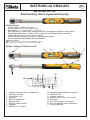
Chiave dinamometrica elettronica
FUNZIONI PRINCIPALI
– Lettura digitale del valore della coppia di serraggio
– Precisione +/- 2% o +/- 3%
– Funzionamento in senso destrorso e sinistrorso
– Selezione delle modalità picco (peak hold) e traccia (track)
– Segnalatore acustico e indicatore LED per la coppia di serraggio desiderata pre-impostabile
– Selezione delle unità di misura (N-m, ft-lb, in-lb, kg-cm)
– Attivazione funzione auto-spegnimento dopo circa 5 minuti di inattività
– Compatibilità con batterie ricaricabili
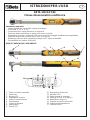
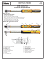
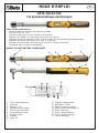
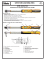
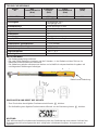
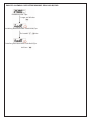
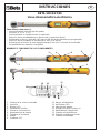
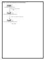
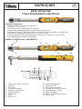
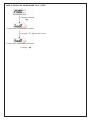
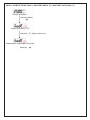
NOMI E FUNZIONI DEI COMPONENTI
1. Testa cricchetto reversibile
2. Inversione
3. Display LCD
4. Segnalatore acustico
5. Porta di comunicazione
6. Vano batteria
7. Coperchio batteria
8. Impugnatura
9. Quadro 1/2”
10. Impugnatura antiscivolo
11. Indicatori LED
12. Valore coppia di serraggio
13. Unità (N-m, ft-lb, in-lb, kg-cm)
14. Modalità picco/traccia
15. Pulsante accensione/cancella
16. Pulsate unità/impostazioni
17. Pulsanti freccia
1
2
3
4
5
6
7
8
10
9
11
12 13
17
14 15
16

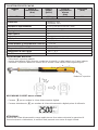
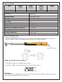
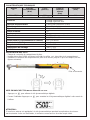
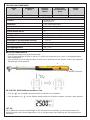
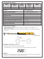
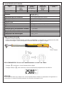
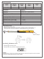
CARATTERISTICHE TECNICHE
Modello Range di Attacco Range di Lunghezza
N°. funzionamento quadro impostazione (mm)
(N-m) (pollici) allarme
(N-m)
599 DGT/20 40-200 1/2” 10-200 519
Beta 599 DGT/20
Precisione destrorso: ±2%
sinistrorso: ±3%
Modalità di funzionamento Picco (Peak Hold)/Traccia (Track)
Selezione unità N-m, ft-lb, in-lb, kg-cm
Tipologia testa Cricchetto reversibile
Denti corona 72
Pulsanti 4
LED luminoso 12 LED/ 4 rossi + 8 verdi
Batteria AA (R6) x 2
Durata batteria (Funzionamento continuo) ~ 110 ore
Durata batteria (Standby) ~ 1 anno
Temperatura di esercizio -10°C / 60°C
Temperatura di stoccaggio -20°C / 70°C
Umidità Fino al 90% senza condensazione
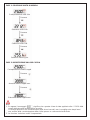
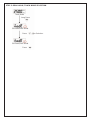
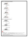
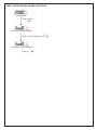
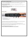
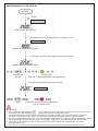
INSTALLAZIONE BATTERIA
– Rimuovere il coperchio batteria.
– Inserire due batterie R6/AA facendo combaciare le polarità -/+ della batteria con il vano batteria.
– Rimettere il coperchio batteria e ruotarlo fino a serrarlo come indicato nelle seguenti figure.
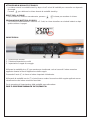
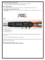
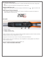
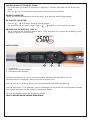
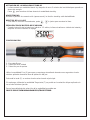
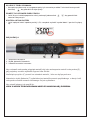
ACCENSIONE E RESET DELLA CHIAVE
– Premere per accendere la chiave dinamometrica digitale.
– Premere abitualmente per resettare la chiave dinamometrica digitale prima di utilizzarla.
ATTENZIONE:
Qualora alla chiave dinamometrica venga applicata una forza esterna durante le operazioni di
accensione/reset o riattivazione, in memoria sarà presente uno scarto di coppia iniziale.
+–
Batteria e coperchio

ATTIVAZIONE IN MODALITÀ STAND-BY
– La chiave entrerà in modalità stand- by dopo circa 5 minuti di inattività per consentire un risparmio
di energia.
Premere per riattivare la chiave durante la modalità stand-by.
RESET DELLA CHIAVE
– Se la chiave non funziona normalmente, premere insieme per resettare la chiave.
SEGNALAZIONE BATTERIA SCARICA
– Se la tensione della batteria è inferiore a 2.3 volt, la chiave visualizza un simbolo batteria e dopo
qualche attimo si spegne.
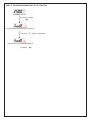
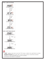
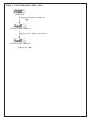
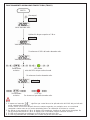
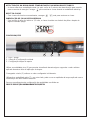
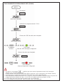
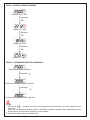
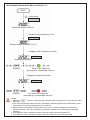
IMPOSTAZIONI
1 - Accensione/Cancella
2 - Selezione/Impostazione unità
3 - Impostazione coppia di serraggio
123
Utilizzare la modalità picco (P) per mantenere visualizzato x alcuni secondi il valore massimo
applicato durante la fase di applicazione della coppia.
Premendo il tasto (C) si ritorna al valore impostato inizialmente.
Utilizzando la modalità traccia (T) si potrà invece vedere l’escursione della coppia applicata senza
visualizzazione del valore massimo esercitato.
Per le procedure di impostazione della modalità prescelta vedere
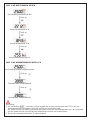
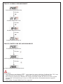
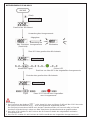
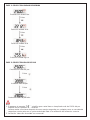
FASE 3: SELEZIONE MODALITA’ PICCO/TRACCIA

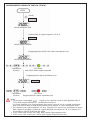
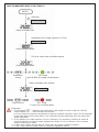
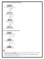
FASE 1: SELEZIONE UNITÀ DI MISURA
Preimpostazione unità: Nm
Selezione unità: in-lb
Selezione unità: ft-lb
Selezione unità: kg-cm
Preimpostazione valore coppia
Aumento valore coppia max.
Riduzione valore coppia max.
Nota:
1. Se appare il messaggio , significa che a questa chiave è stata applicato oltre il 110% della
coppia indicata nelle caratteristiche tecniche.
La chiave riprende il suo funzionamento dopo alcuni secondi, ma si consiglia entro tempi brevi
una verifica della corretta taratura della chiave presso un centro autorizzato Beta.
2. La funzione “selezione unità” è sequenziale.
Premere
Premere
Premere
Premere
Premere
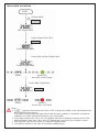
FASE 2: IMPOSTAZIONE VALORE COPPIA

FASE 3: SELEZIONE MODALITÀ PICCO / TRACCIA
Modalità traccia
Impostazione modalità picco/traccia
Premere a lungo
Premere per selezionare
Impostazione modalità peak/track
Premere

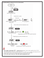
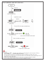
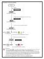
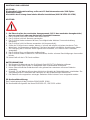
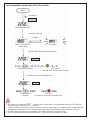
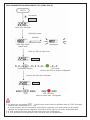
FUNZIONAMENTO MODALITÀTRACCIA (TRACK)
INIZIO
Valore desiderato max.
Valore coppia corrente
Valore coppia corrente
(Avvio)
* Nota 1
Applicazione di coppia superiore a 5 N-m
Raggiungimento del 90% del valore desoderato max.
* Nota 2
Segnalatore
acustico
LED verde
oltre il 90% della coppia impostata
Segnalatore
acustico
LED rosso
Raggiungimento coppia impostata max.
Raggiungimento valore desiderato max.
* Nota 3
Nota:
1. Se compare il messaggio , significa che a questa chiave è stato applicato oltre il
110% della coppia indicata nelle caratteristiche tecniche.
La chiave riprende il suo funzionamento dopo alcuni secondi, ma si consiglia entro tempi
brevi una verifica della corretta taratura della chiave presso un centro autorizzato Beta.
2. Se si applica una coppia superiore a 5 N-m, il display LCD comincia a visualizzare il valore
della coppia di serraggio. Qualora la coppia applicata sia inferiore a 5 N-m, il display LCD
non evidenzia alcuna variazione del valore.
3. Il LED verde sarà acceso per il 90% della coppia d’impostazione max.
4. Il LED rosso sarà acceso per il 100% della coppia d’impostazione max.

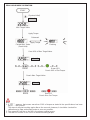
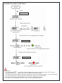
FUNZIONAMENTO MODALITÀ PICCO (PEAK HOLD)
INIZIO
Valore desiderato max.
Valore coppia corrente max.
(peak hold)
(Avvio)
* Nota 1
* Nota 2
Applicazione coppia
Oltre il 90% del valore desiderato max.
Segnalatore acustico LED verde
Raggiungimento del 90% della coppia impostata
Segnalatore
acustico
LED rosso
Raggiungimento coppia impostata max.
Raggiungimento valore desiderato max.
* Nota 3
Nota:
1. Se compare il messaggio , significa che a questa chiave è stato applicato oltre il 110%
della coppia indicata nelle caratteristiche tecniche.
La chiave riprende il suo funzionamento dopo alcuni secondi, ma si consiglia entro tempi brevi una
verifica della corretta taratura della chiave presso un centro autorizzato Beta.
2. Il LED verde sarà acceso per il 90% della coppia d’impostazione max.
3. Il LED rosso sarà acceso per il 100% del valore d’impostazione max.
Rilasciato
Applicazione coppia
Lampeggiante

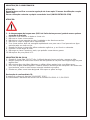
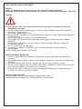
MANUTENZIONE E STOCCAGGIO
ATTENZIONE:
Si raccomanda di far controllare la corretta taratura della chiave dopo 12 mesi di utilizzo o
5000 cicli.
Per la taratura contattare il proprio rivenditore locale (UNI EN 26789 ISO 6789)
ATTENZIONE:
1. Il superamento della coppia max. (105% del range di coppia max.) potrebbe causare rotture
o perdita di precisione.
2. Non scuotere violentemente o far cadere la chiave.
3. Non usare la chiave come martello.
4. Non lasciare la chiave esposta a eccessivo calore, umidità o luce solare diretta.
5. Non usare la chiave in acqua (non è impermeabile)
6. Se la chiave si bagna, asciugarla al più presto con panno asciutto. Il sale presente nell’acqua
marina può rivelarsi particolarmente dannoso.
7. Quando si pulisce la chiave non utilizzare solventi organici, p. es. alcool o solventi.
8. Conservare la chiave lontano da calamite.
9. Non esporre la chiave alla polvere o alla sabbia, che potrebbero causare gravi danni.
10.Non applicare forze al pannello LCD.
MANUTENZIONE BATTERIA
1. Quando la chiave Beta 599 DGT non viene utilizzata per lunghi periodi, rimuovere la batteria.
2. Tenere una batteria di riserva a portata di mano quando si parte per un lungo viaggio o ci si dirige
verso zone fredde.
3. Non mischiare tipi diversi di batterie o utilizzare batterie usate insieme a batterie nuove.
4. Sudore, olio e acqua possono impedire il contatto elettrico dei morsetti di una batteria. Per evitare
questo inconveniente, asciugare i due morsetti prima di inserire una batteria.
5. Smaltire le batterie in un’area designata. Non esporre le batterie al fuoco.
Dichiarazione di conformità CE:
Il prodotto è conforme alla direttiva 2004/108/EC (EMC).
La conformità è dichiarata in accordo con le norme EN 61000- 6-2 / EN 55011.

INSTRUCTIONS
EN
BETA 599 DGT/20
Electronic Torque Wrench
MAIN FEATURES
– Digital torque value readout
– +/- 2% or +/- 3% accuracy
– CW and CCW operation
– Peak hold and track mode selectable
– Buzzer and LED indicator for presettable target torque
– Engineering units (N-m, ft-lb, in-lb, kg-cm) selectable
– Auto Sleep after about 5 minutes idle
– Rechargeable batteries are compatible
NAMES AND FUNCTIONS OF PARTS
1. Reversible Ratchet Head
2. Direction Lever
3. LCD Readout
4. Buzzer
5. Calibration Port
6. Battery Compartment
7. Battery Cover
8. Handle
9. 1/2” Square Drive
10. Antislip Handle
11. LED Indicators
12. Torque Value
13. Unit (N-m,ft-lb,in-lb,kg-cm)
14. Peak/Track Mode
15. Power On / Clear Button
16. Unit/Setting Button
17. Up/Down Button
11
12 13
17
14 15
16
1
2
3
4
5
6
7
8
10
9

SPECIFICATIONS
Model Operation Square Alarm Lenght
N°. Range Drive Setting (mm)
(N-m) (inches) Range
(N-m)
599 DGT/20 40-200 1/2” 10-200 519
Beta 599 DGT/20
Accuracy CW: ±2%
CCW: ±3%
Operation Mode Peak Hold / Track
Unit Selection N-m, ft-lb, in-lb, kg-cm
Head Type Reversible ratchet
Gear Teeth 72
Buttons 4
Bright LED 12 LEDs / 4 red + 8 green
Battery AA (R6) x 2
Battery Life (Continuous Operation) ~ 110 hours
Battery Life (Standby) ~ 1 year
Operating Temperature -10°C / 60°C
Storage Temperature -20°C / 70°C
Humidity Up to 90% non-condensingone
BATTERY INSTALLATION
– Remove the battery cover.
– Insert two R6/AA batteries matching the -/+ polarities of the battery to the battery compartment.
– Put on the battery cover and rotate it tightly according to the following figures.
POWER ON AND RESETTING WRENCH
– Press to power on the digital torque wrench.
– Usually press to reset the digital torque wrench before using it.
ATTENTION:
If an external force is applied to the torque wrench during the power-on/reset or wake up period, an
initial torque offset will be found in the memory.
+–
Battery and cover

ACTIVATION DURING SLEEP MODE
– The wrench will auto sleep after about 5 minutes idle for power saving.
Press to wake up the wrench during the sleep mode.
RESETTING WRENCH
– If the wrench does not function normally, press together to reset the wrench.
LOW BATTERY VOLTAGE PROTECTION
– If the battery voltage is under 2.3 volts, the wrench will display a battery symbol and then turn off
after a while.
SETUP
1 - Power On/Clear
2 - Unit Selection/Setting
3 - Set Torque Value
123
Use peak hold mode (P) to keep the maximum value achieved while applying torque displayed for a
few seconds.
Pressing (C) will allow the preset value to be restored.
Whereas using track mode (T) will allow the applied torque range to be viewed, without the maximum
applied value being displayed.
To set the chosen mode go to:
STEP 3: PEAK HOLD /TRACK MODE SELECTION

STEP 1: UNIT SELECTION
Presetting Unit: Nm
Unit Selection: in-lb
Unit Selection: ft-lb
Unit Selection: kg-cm
Presetting Torque Value
Increase Max.Torque Value
Decrease Max.Torqur Value
Note:
1. If appears, that means more than 110% torque as stated in the specifications has been
applied to this wrench.
The wrench will start working again after a few seconds; however, it should be checked for
calibration at a Beta authorized centre as soon as possible.
2. The function “Unit Selection” is sequential.
Press
Press
Press
Press
Press
STEP 2: SET TORQUE VALUE

STEP 3: PEAK HOLD /TRACK MODE SELECTION
Track Mode
Set Peak/Track Mode
Long Press
Press for Selection
Set Peak/Track Mode
Press

TRACK MODE OPERATION
START
Max.Target Value
Current Target Value
Current Torque Value
(Sistem initial)
* Note 1
Appliy Torque Over 5 N-m
Reach 90% od Max. Target Value
* Note 2
Buzzer Green LED
Over 90% of Set Torque
Buzzer Red LED
Reach Max. Set Torque
Reach Max.Target Value
* Note 3
Note:
1. If appears, that means more than 110% of torque as stated in the specifications has
been applied to this wrench.
The wrench will start working again after a few seconds; however, it should be checked for
calibration at a Beta authorized centre as soon as possible.
2. If you apply torque over 5 N-m, the LCD display will start to display the torque value. If the
applied torque is less than 5 N-m, the LCD display does not show any changes in value.
3. The green LED will be on for 90% of maximum setting torque.
4. The red LED will be on for 100% of maximum setting torque.

PEAK HOLD MODE OPERATION
START
Max.Target Value
Current Max.Value
(Peak Hold)
(System initial)
* Note 1
* Note 2
Apply Torque
Over 90% of Max.Target Value
Buzzer Green LED
Reach 90% of Set Torque
Buzzer Red LED
Reach Max. Set Torque
Reach Max.Target Value
* Note 3
Note:
1. If appears, that means more than 110% of torque as stated in the specifications has been
applied to this wrench.
The wrench will start working again after a few seconds; however, it should be checked for
calibration at a Beta authorized centre as soon as possible.
2. The green LED will be on for 90% of maximum setting torque.
3. The red LED will be on for 100% of maximum setting torque.
Released
Apply Torque
Flashing

MAINTENANCE AND STORAGE
ATTENTION:
It is recommended that the wrench be checked for calibration after 12 months’ operation or
after 5,000 cycles.
Please contact your local dealer for calibrations (UNI EN 26789 - ISO 6789)
ATTENTION:
1. Over-torque (105% of max. torque range) could cause breakage or lose accuracy.
2. Do not shake violently or drop wrench.
3. Do not use this wrench as a hammer.
4. Do not leave this wrench in any place exposed to excessive heat, humidity or direct sunlight.
5. Do not use this apparatus in water (it is not waterproof).
6. If the wrench gets wet, wipe it with a dry cloth.The salt in seawater can be especially damaging.
7. Do not use any organic solvents, such as alcohol or paint thinner, when cleaning the wrench.
8. Keep this wrench away from magnets.
9. Do not expose this wrench to dust or sand, as this could cause serious damage.
10.Do not apply any force to the LCD panel.
BATTERY MAINTENANCE
1. When the Beta 599 DGT wrench is not used for an extended period of time, remove the battery.
2. Keep a spare battery on hand when going on a long trip or to cold areas.
3. Do not mix battery types or combine used batteries with new ones.
4. Sweat, oil and water can prevent a battery’s terminal from making electrical contact. To avoid this,
wipe both terminals before loading a battery.
5. Dispose of batteries in a designated disposal area. Do not throw batteries into a fire.
EC Declaration of Conformity:
The product complies with the requirements of Directive 2004/108/EC (EMC).
Conformity is declared in accordance with EN 61000- 6-2 / EN 55011.

MODE D’EMPLOI
F
BETA 599 DGT/20
Clé dynamométrique électronique
FONCTIONS PRINCIPALES
– Lecture digitale de la valeur du couple de serrage
– Précision ± 2% ou ± 3%
– Fonctionnement dans le sens horaire et anti-horaire
– Sélection des modes de crête (peak hold) et de suivi (track)
– Indicateur sonore et indicateur à DEL pour le couple de serrage désiré présélectionnable
– Sélection des unités de mesure (N-m, ft-lb, in-lb, kg-cm)
– Activation fonction d’auto-extinction après environ 5 minutes d’inactivité
– Compabile avec les piles rechargeables
NOMS ET FONCTIONS DES COMPOSANTS
1. Tête cliquet réversible
2. Inversion
3. Afficheur LCD
4. Avertisseur acoustique
5. Port de communication
6. Compartiment à piles
7. Couvercle piles
8. Poignée
9. Carré 1/2”
10. Poignée antidérapante
11. Indicateurs à DELs
12. Valeur couple de serrage
13. Unités (N-m,ft-lb,in-lb,kg-cm)
14. Mode crête/suivi
15. Touche marche/effacer
16. Touche unités/réglages
17. Touche haut/bas
11
12 13
17
14 15
16
1
2
3
4
5
6
7
8
10
9

CARACTÉRISTIQUESTECHNIQUES
Modèle Plage de Carré: Plage de Longueur
N°. fonctionnement (pouces) sélection (mm)
(N-m) alarme
(N-m)
599 DGT/20 40-200 1/2” 10-200 519
Beta 599 DGT/20
Précision serrage à droite ±2%
serrage à gauche: ±3%
Mode de fonctionnement Crête (Peak Hold)/Suivi (Track)
Sélection unité N-m, ft-lb, in-lb, kg-cm
Type de tête Cliquet réversible
Dents couronne 72
Boutons 4
DELs lumineux 12 DELs / 4 rouges + 8 vertes
Pile AA (R6) x 2
Durée batterie (Fonctionnement en continu) env. 110 heures
Durée batterie (Veille) env. 1 an
Température de fonctionnement -10°C / 60°C
Température de stockage -20°C / 70°C
Humidité Jusqu’à 90% sans condensation
INSTALLATION DES PILES
– Enlever le couvercle du compartiment à piles.
– Installer deux piles R6/AA en faisant coïncider les pôles + et - des piles et du compartiment.
– Remettre le couvercle du compartiment à piles et le tourner jusqu’à ce qu’il soit bloqué (voir les
figures suivantes).
MISE EN MARCHE ET REMISE À ZÉRO DE LA CLÉ
– Appuyer sur pour allumer la clé dynamométrique digitale.
– Prenez l’habitude d’appuyer sur pour remettre la clé dynamométrique digitale à zéro avant de
l’utiliser.
ATTENTION :
Si une force externe est appliquée à la clé dynamométrique pendant les opérations de mise en
marche/remise à zéro ou réactivation, la mémoire conservera un écart de couple initial.
+–
Piles et couvercle

ACTIVATION EN MODE VEILLE
– La clé passe en mode veille après environ 5 minutes d’inactivité afin d’économiser l’énergie des
piles.
Appuyer sur pour réactiver la clé lorsqu’elle est en mode veille.
REMISE À ZÉRO DE LA CLÉ
– Si la clé ne fonctionne pas correctement, appuyer simultanément sur pour mettre à zéro
la clé.
INDICATION BATTERIE DÉCHARGÉE
– Si la tension de la batterie est inférieure à 2,3 Volts, la clé affiche le symbole de la batterie et
s’arrête quelques instants plus tard.
REGLAGES
1 - Marche / Effacer
2 - Sélection / Réglage unité
3 - Réglage couple de serrage
123
Utiliser le mode de crête (P) pour maintenir affichée pendant quelques secondes la valeur maximum
appliquée pendant la phase d'application du couple.
Appuyer sur la touche (C) pour revenir à la valeur sélectionnée initialement.
Utiliser le mode suivi (T) pour visualiser par contre l'amplitude du couple appliqué sans afficher la
valeur maximum exercée.
Pour les procédures de sélection du mode prédéfini, voir
ÉTAPE 3 : SÉLECTION MODE CRÊTE/SUIVI
Strona się ładuje...
Strona się ładuje...
Strona się ładuje...
Strona się ładuje...
Strona się ładuje...
Strona się ładuje...
Strona się ładuje...
Strona się ładuje...
Strona się ładuje...
Strona się ładuje...
Strona się ładuje...
Strona się ładuje...
Strona się ładuje...
Strona się ładuje...
Strona się ładuje...
Strona się ładuje...
Strona się ładuje...
Strona się ładuje...
Strona się ładuje...
Strona się ładuje...
Strona się ładuje...
Strona się ładuje...
Strona się ładuje...
Strona się ładuje...
Strona się ładuje...
Strona się ładuje...
Strona się ładuje...
Strona się ładuje...
Strona się ładuje...
Strona się ładuje...
Strona się ładuje...
Strona się ładuje...
Strona się ładuje...
Strona się ładuje...
Strona się ładuje...
Strona się ładuje...
Strona się ładuje...
Strona się ładuje...
Strona się ładuje...
Strona się ładuje...
Strona się ładuje...
Strona się ładuje...
Strona się ładuje...
Strona się ładuje...
Strona się ładuje...
Strona się ładuje...
Strona się ładuje...
Strona się ładuje...
-
 1
1
-
 2
2
-
 3
3
-
 4
4
-
 5
5
-
 6
6
-
 7
7
-
 8
8
-
 9
9
-
 10
10
-
 11
11
-
 12
12
-
 13
13
-
 14
14
-
 15
15
-
 16
16
-
 17
17
-
 18
18
-
 19
19
-
 20
20
-
 21
21
-
 22
22
-
 23
23
-
 24
24
-
 25
25
-
 26
26
-
 27
27
-
 28
28
-
 29
29
-
 30
30
-
 31
31
-
 32
32
-
 33
33
-
 34
34
-
 35
35
-
 36
36
-
 37
37
-
 38
38
-
 39
39
-
 40
40
-
 41
41
-
 42
42
-
 43
43
-
 44
44
-
 45
45
-
 46
46
-
 47
47
-
 48
48
-
 49
49
-
 50
50
-
 51
51
-
 52
52
-
 53
53
-
 54
54
-
 55
55
-
 56
56
-
 57
57
-
 58
58
-
 59
59
-
 60
60
-
 61
61
-
 62
62
-
 63
63
-
 64
64
-
 65
65
-
 66
66
-
 67
67
-
 68
68


Beta 599DGT Instrukcja obsługi
- Typ
- Instrukcja obsługi
- Niniejsza instrukcja jest również odpowiednia dla
w innych językach
- español: Beta 599DGT Instrucciones de operación
- italiano: Beta 599DGT Istruzioni per l'uso
- Deutsch: Beta 599DGT Bedienungsanleitung
- português: Beta 599DGT Instruções de operação
- français: Beta 599DGT Mode d'emploi
- Nederlands: Beta 599DGT Handleiding