Planet WGS-6325-8UP2X Skrócona instrukcja obsługi
- Typ
- Skrócona instrukcja obsługi

Industrial Wall-mount Managed
Gigabit Ethernet Switch
WGS-6325-8UP2X
User's Manual

Table of Contents
1. Package Contents ................................................................................. 3
2. Requirements ....................................................................................... 4
3. Hardware Installation ............................................................................ 5
3.1 Wall Mount Installation ................................................................... 5
3.2 Wall Hanging Installation ................................................................ 6
3.3 Grounding the Device ..................................................................... 7
4. Wiring the Power and Alarm Inputs ....................................................... 8
4.1 Terminal Block Connector Pinout ..................................................... 9
4.2 Wiring Completed in Three Steps .................................................... 9
4.3 Wiring the Alarm Contact ............................................................. 10
5. Web Login ......................................................................................... 11
5.1 Starting Web Management............................................................ 11
5.2 SavingCongurationviatheWeb .................................................. 13
6. SSH Login ......................................................................................... 14
6.1 ConguringIPAddress ................................................................. 15
6.2 StoringtheCurrentSwitchConguration ....................................... 17
7. RecoveringBacktoDefaultConguration ............................................. 18
8. Customer Support .............................................................................. 19

3
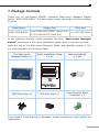
1. Package Contents
Thank you for purchasing PLANET Industrial Wall-mount Managed Gigabit
Switch, WGS-6325-8UP2X. The table below shows the model with the number
of ports:
Model Name Copper Port Fiber Port
WGS-6325-8UP2X 4 x 10/100/1000/2500T (Ports 1-4)
4 x 10/100/1000T (Ports 5-8) 2 x 1G/2.5G/10GX
In the following sections, unless specied, the term “Wall-mount Managed
Switch” mentioned in this quick installation guide refers to the above model.
Open the box of the Wall-mount Managed Switch and carefully unpack it. The
box should contain the following items:
The Wall-mount
Managed Switch x 1
Quick Installation Guide
x 1 pc
Wall-mounted Kit
x 1 set
Let’s get started with your PLANET product
WGS-6325-8UP2X
EN Please scan the QR code to browse our online User’s Manual or Quick
Installation Guide and follow the instructions to complete the setup.
Quick
Installation
DE
Bitte scannen Sie den QR Code sie werden per Browser zur
Bedienungsanleitung oder Schnellanleitung weiter geleitet. Folgen Sie den
Anweisungen um die Installation abzuschließen.
FR
Veuillez scanner le code QR pour obtenir notre Notice d’Utilisation en
ligne ou notre Guide d’Installation Rapide et suivez les instructions pour
compléter la conguration
ES
Escanee el código QR para encontrar el Manual del Usuario en línea o
la Guía de Instalación Rápida y siga las instrucciones para completar la
conguración.
IT Scansiona il codice QR per consultare online il Manuale utente o la Guida di
installazione rapida e segui le istruzioni per completare la congurazione.
PT Por favor, escaneie o QR code para navegar no Manual do Usuário ou Guia
de Instalação Rápida. Siga as instruções para completar a conguração.
PL
Zeskanuj kod QR, aby otworzyć naszą internetową instrukcję obsługi
lub instrukcję szybkiej instalacji. Postępuj zgodnie z instrukcjami, aby
zakończyć poprawną kongurację.
RU
One word modify: Отсканируйте QR-код, чтобы просмотреть наше
онлайн-руководство пользователя или руководство по быстрой
настройке, и следуйте инструкциям для завершения настройки
RO Te rugam sa scanezi codul QR, pentru a descarca User’s Manual sau Quick
Installation Guide si a urmari instructiunile necesare in nalizarea instalarii
AR
Need more help?
PLANET online FAQs:
http://www.planet.com.tw/en/support/faq
Technical Support: [email protected]
Copyright © PLANET Technology Corp. 2023.
Contents are subject to revision without prior notice.
PLANET is a registered trademark of PLANET Technology Corp.
All other trademarks belong to their respective owners.
Part No. 2340-A36140-000
RJ45 Dust Cap x 8 SFP Dust Cap x 2 2-pin Terminal Block
Connector x 1
If any item is found missing or damaged, please contact your local reseller for
replacement.

4
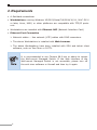
2. Requirements
• Aat-bladescrewdriver
• Workstations running Windows XP/2003/Vista/7/8/2008/10/11, MAC OS X
or later, Linux, UNIX, or other platforms are compatible with TCP/IP proto-
cols.
• WorkstationsareinstalledwithEthernet NIC (Network Interface Card)
• Ethernet Port Connection
Network cables -- Use network (UTP) cables with RJ45 connectors.
The above Workstations is installed with Web browser.
The above Workstations have been installed with SSH and telnet client
software, such as Tera Term or PuTTY.
It is recommended to use Chrome 98.0.xxx or above to access
the Wall-mount Managed Switch. If the Web interface of the
Wall-mount Managed Switch is not accessible, please turn off
the anti-virus software or firewall and then try it again.

5
3. Hardware Installation
3.1 Wall Mount Installation
To install the Wall-mount Managed Switch on the wall, simply follow the
following steps:
Step 1: Drill 4 holes with 8mm diameter on the wall. The horizontal and
vertical distances between the 2 holes are 230mm and 124mm,
respectively.
230mm
124mm
Ø4mm
6mm
Ø8mm
Step 2: Hammer the four anchors into the four holes.
1 2

6
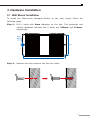
Step 3: Then the four given screws are screwed into the anchors to nish
the wall-mount installation, as shown below.
ACTLNK
ACTLNK
1G/2.5G
10G
1G/2.5G LNK/ACT
10/100 LNK/ACT
bt PoE-in-Use
at PoE-in-Use
3 421 7 865
PoE++
V1 V1+
PWR 2
V2 V2+
PWR 1
DC Input Range
48-54V
, 11A max.
Dual power input
is required for
maximum PoE loading.
R.O.
Ring
PWR 2
PWR 1
SFP+
9
10
SFP+
10/100/1000/2500T 10/100/1000T
910
WGS-6325-8UP2X
Managed
Fiber 10G SFP+
PoE++
Alarm
Max. Fault Alarm
Loading: 24V, 1A
230mm
124mm
3.2 Wall Hanging Installation
To hang the Wall-mount Managed Switch on the wall, simply follow the
following steps:
Step 1: Drill 2 holes (one hole on each side) with 8mm diameter on the wall;
the distance between the 2 holes is 230 mm and the line through
them must be horizontal.
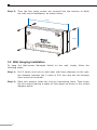
Step 2: Place two anchors inside the hole by hammering them. Then screw
the two screws leaving a space of 2mm apart as shown in the circled
diagram below.

7
Step 3: The switch, shown in the picture below, can now be hung on the
wall.
ACTLNK
ACTLNK
1G/2.5G
10G
1G/2.5G LNK/ACT
10/100 LNK/ACT
bt PoE-in-Use
at PoE-in-Use
3 421 7 865
PoE++
V1 V1+
PWR 2
V2 V2+
PWR 1
DC Input Range
48-54V
, 11A max.
Dual power input
is required for
maximum PoE loading.
R.O.
Ring
PWR 2
PWR 1
SFP+
9
10
SFP+
10/100/1000/2500T 10/100/1000T
910
WGS-6325-8UP2X
Managed
Fiber 10G SFP+
PoE++
Alarm
Max. Fault Alarm
Loading: 24V, 1A
1 Place against a wall
2 Hang up
4mm Screw
Make sure the equipment is securely wall-mounted as strong
vibration could cause it to drop or break.
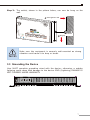
3.3 Grounding the Device
User MUST complete grounding wired with the device; otherwise, a sudden
lightning could cause fatal damage to the device. EMD (Lightning) DAMAGE IS
NOT COVERED UNDER WARRANTY.
9 10
Reset
1G/2.5G/10G
Earth Ground

8
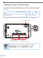
4. Wiring the Power and Alarm Inputs
The Wall-mount Managed Switch features a strong dual power input system
incorporated into customer’s automation network to enhance system reliability
and uptime.
Power Input Range
Model PWR1 PWR2
WGS-6325-8UP2X DC 48-54V, 11A max
Note: Maximum power requirements also rely on the real site application.
ACTLNK
ACTLNK
1G/2.5G
10G
1G/2.5G LNK/ACT
10/100 LNK/ACT
bt PoE-in-Use
at PoE-in-Use
3 421 7 865
PoE++
V1 V1+
PWR 2
V2 V2+
PWR 1
DC Input Range
48-54V
, 11A max.
Dual power input
is required for
maximum PoE loading.
R.O.
Ring
PWR 2
PWR 1
SFP+
9
10
SFP+
10/100/1000/2500T 10/100/1000T
9 10
WGS-6325-8UP2X
ManagedFiber 10G SFP+
PoE++
Alarm
Max. Fault Alarm
Loading: 24V, 1A
10/100/1000/2500T
802.3bt PoE++ RJ45 Port
10/100/1000T
802.3bt PoE++ RJ45 Port
4-pin Spring Terminal Block
V1 V1+
PWR 2
V2 V2+
PWR 1
DC Input Range
48-54V
, 11A max.
Dual power input is required for maximum PoE loading
Single power input: Max. 240 watts PoE budget
Dual power input: Max. 480 watts PoE budget

9
PWR1 and PWR2 must provide exactly the same DC voltage
for power load balance while operating with dual power input.
4.1 Terminal Block Connector Pinout
The Front Panel of the Wall-mount Managed Switch consists of one spring
terminal block connector within 4 contacts. Please follow the steps below to
insert the power wire.
V1 V1+
PWR 2 PWR 1
V2 V2+
Insert positive/negative DC power wires into Contacts V1+ and V1- for Power
1, or Contacts V2+ and V2- for Power 2.
4.2 Wiring Completed in Three Steps
Step 1: Presstheat-bladescrewdriverdiagonallyintothereleasehole.
Step 2: Leave the at-blade screwdriver pressed into the release hole and
insert the wire into the terminal hole. Insert the wire until the
stripped portion is no longer visible to prevent shorting.
Step 3: Remove the at-blade screwdriver from the release hole. After you
connect the wires, pull gently on the wire to make sure that it will
notcomeoandthewireissecurelyfastenedtotheterminalblock.
ACTLNK
ACTLNK
1G/2.5G
10G
1G/2.5G LNK/ACT
10/100 LNK/ACT
bt PoE-in-Use
at PoE-in-Use
3 421 7 865
PoE++
V1 V1+
PWR 2
V2 V2+
PWR 1
DC Input Range
48-54V
, 11A max.
Dual power input
is required for
maximum PoE loading.
R.O.
Ring
PWR 2
PWR 1
SFP+
9
10
SFP+
10/100/1000/2500T 10/100/1000T
910
WGS-6325-8UP2X
Managed
Fiber 10G SFP+
PoE++
Alarm
Max. Fault Alarm
Loading: 24V, 1A
V1 V1+
PWR 2
V2 V2+
PWR 1
DC Input Range
48-54V
, 11A max.
Wire
Flat-blade screwdriver
1
2

10
3
ACTLNK
ACTLNK
1G/2.5G
10G
1G/2.5G LNK/ACT
10/100 LNK/ACT
bt PoE-in-Use
at PoE-in-Use
3 421 7 865
PoE++
V1 V1+
PWR 2
V2 V2+
PWR 1
DC Input Range
48-54V
, 11A max.
Dual power input
is required for
maximum PoE loading.
R.O.
Ring
PWR 2
PWR 1
SFP+
9
10
SFP+
10/100/1000/2500T 10/100/1000T
910
WGS-6325-8UP2X
Managed
Fiber 10G SFP+
PoE++
Alarm
Max. Fault Alarm
Loading: 24V, 1A
Flat-blade screwdriver
V1 V1+
PWR 2
V2 V2+
PWR 1
DC Input Range
48-54V
, 11A max.
Wire
The wire gauge should be in the range from 12 to 16 AWG.
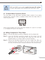
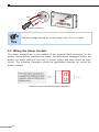
4.3 Wiring the Alarm Contact
The alarm contacts are in the middle of the terminal block connector as the
picture shows below. Inserting the wires, the Wall-mount Managed Switch will
detect the event status of the port or power failure and then forms an open
circuit. The following illustration shows an application example for wiring the
alarm contacts.
Insert the wires into the fault alarm contacts.

11
5. Web Login
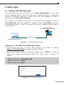
5.1 Starting Web Management
The following shows how to start up the Web Management of the Wall-
mount Managed Switch. Note the Wall-mount Managed Switch is congured
through an Ethernet connection. Please make sure the manager PC must be
set to the same IP subnet address.
For example, the default IP address of the Wall-mount Managed Switch is
192.168.0.100, then the manager PC should be set to 192.168.0.x (where x
is a number between 1 and 254, except 100) and the default subnet mask is
255.255.255.0.
PC / Workstation
with Web Browser 192.168.0.x
Managed Switch
RJ45/UTP Cable
IP Address: 192.168.0.100
Figure 5-1: IP Management Diagram
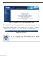
Logging in to the Wall-mount Managed Switch
1. Use Chrome 98.0.xxx or above Web browser and enter IP address
https://192.168.0.100 to access the Web interface.
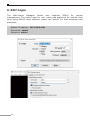
2. When the following dialog box appears, please enter “admin” in both the
default user name and password elds. The login screen in Figure 5-2
appears.
Default IP Address: 192.168.0.100
Default Username: admin
Default Password: admin
Figure 5-2: Web Login Screen

12
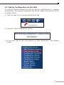
3. After entering the password, the main screen appears as Figure 5-3 shows.
Figure 5-3: Web Main Screen of Wall-mount Managed Switch
The Switch Menu on the top of the Web page lets you access all the
commands and statistics the Wall-mount Managed Switch provides. The Switch
Menu always contains one or more buttons, such as “System”, “Switching”,
“Routing”, “QoS”, “Security”, “PoE”, “Ring”, “ONVIF” and “Maintenance”.
Figure 5-4: Switch Menu
If you are not familiar with Switch functions or the related
parameter, press “Help icon” anytime on the Web page to get
the help description.

13
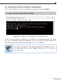
5.2 SavingCongurationviatheWeb
To save all applied changes and set the current conguration as a startup
conguration, the startup-conguration le will be loaded automatically across
a system reboot.
1. Click the Save icon on the top Switch Menu bar.
2.Pressthe“SaveConguration”button.
3. Or the other way to save the setting is to Click Maintenance, Save Startup
Cong.

14
6. SSH Login
The Wall-mount Managed Switch also supports SSHv2 for remote
management. The switch asks for user name and password for remote login
when using SSHv2 client software; please use “admin” for both username and
password.
Default IP address: 192.168.0.100
Username: admin
Password: admin

15
Figure 6-1: Wall-mount Managed Switch SSHv2 Login Screen
The user can now enter commands to manage the Wall-mount Managed
Switch. For a detailed description of the commands, please refer to the
following chapters.
1. For security reason, please change and memorize the
new password after this first setup.
2. Only accept command in lowercase letter under console inter-
face..
6.1 ConguringIPAddress
The Wall-mount Managed Switch is shipped with default IP address shown
below:
IP Address: 192.168.0.100
Subnet Mask: 255.255.255.0
To check the current IP address or modify a new IP address for the Switch,
please use the procedure as follows:
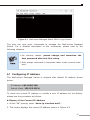
Display of the Current IP Address
1. At the “#” prompt, enter “show ip interface brief”.
2. The screen displays the current IP address shown in Figure 6-2.

16
Figure 6-2: IP Information Screen
Conguration of the IP Address
3. At the “#” prompt, enter the following command and press <Enter> as
shown in following.
Figure 6-3: Set IP Address Command Screen
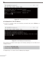
The previous command would apply the following settings for the Wall-mount
Managed Switch.
IP Address: 192.168.1.100
Subnet Mask: 255.255.255.0
4. Repeat step 1 to check if the IP address has changed.

17
6.2 StoringtheCurrentSwitchConguration
At the “#” prompt, enter the following command and press <Enter>.
# copy running-cong startup-cong
Figure 6-4: Saving Current Conguration Command Screen
If the IP is successfully congured, the Wall-mount Managed Switch will apply
the new IP address setting immediately. You can access the Web interface of
the Wall-mount Managed Switch through the new IP address.
If you are not familiar with the command line interface(CLI) or
the related parameter, enter “help” anytime in CLI to get the
help description.

18
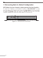
7.RecoveringBacktoDefaultConguration
IP Address has been changed or admin password has been forgotten –
To reset the IP address to the default IP address “192.168.0.100” or reset
the login password to default value, press the reset button on the front panel
for about 5 seconds. After the device is rebooted, you can log in the Web
interface management within the same subnet of 192.168.0.xx.
9 10
Reset
1G/2.5G/10G
Figure 7-1: WGS-6325-8UP2X Reset Button

19
8. Customer Support
Thank you for purchasing PLANET products. You can browse our online FAQ
resource and User’s Manual on PLANET Web site rst to check if it could solve
your issue. If you need more support information, please contact PLANET
switch support team.
PLANET online FAQs:
https://www.planet.com.tw/en/support/faq
Switch support team email address:
WGS-6325-8UP2X User’s Manual:
https://www.planet.com.tw/en/support/downloads?&method=keyword&keyword
=WGS&view=3#list
Copyright © PLANET Technology Corp. 2023.
Contents are subject to revision without prior notice.
PLANET is a registered trademark of PLANET Technology Corp.
All other trademarks belong to their respective owners.
-
 1
1
-
 2
2
-
 3
3
-
 4
4
-
 5
5
-
 6
6
-
 7
7
-
 8
8
-
 9
9
-
 10
10
-
 11
11
-
 12
12
-
 13
13
-
 14
14
-
 15
15
-
 16
16
-
 17
17
-
 18
18
-
 19
19


Planet WGS-6325-8UP2X Skrócona instrukcja obsługi
- Typ
- Skrócona instrukcja obsługi
w innych językach
Powiązane artykuły
Inne dokumenty
-
 Allen-Bradley Stratix 8000 Installation Instructions Manual
-
3com Switch 4500 PWR 50-Port Getting Started Manual
-
ZyXEL XGS1210-12 12-Port Web-Managed Multi-Gigabit Switch Skrócona instrukcja obsługi
-
Intellinet 24-Port Gigabit Ethernet PoE Web-Managed Switch with 2 SFP Ports Quick Installation Guide
-
Intellinet 8-Port Gigabit Ethernet PoE Web-Managed Switch with 2 SFP Ports Quick Installation Guide
-
Intellinet 24-Port Gigabit Ethernet PoE Web-Managed Switch with 4 Gigabit Combo Base-T/SFP Ports Quick Instruction Guide
