Yamaha CS-R5 Instrukcja obsługi
- Kategoria
- Kontrolery DJ
- Typ
- Instrukcja obsługi

EN
CONTROL SURFACE
CS-R5
Owner’s Manual

Explanation of Graphical Symbols
Explication des symboles
The lightning flash with arrowhead symbol within an equilateral triangle is intended to alert the user to the presence of uninsulated
“dangerous voltage” within the product’s enclosure that may be of sufficient magnitude to constitute a risk of electric shock to persons.
L’éclair avec une flèche à l’intérieur d’un triangle équilatéral est destiné à attirer l’attention de l’utilisateur sur la présence d’une
« tension dangereuse » non isolée à l’intérieur de l’appareil, pouvant être suffisamment élevée pour constituer un risque d’électrocution.
The exclamation point within an equilateral triangle is intended to alert the user to the presence of important operating and maintenance
(servicing) instructions in the literature accompanying the product.
Le point d’exclamation à l’intérieur d’un triangle équilatéral est destiné à attirer l’attention de l’utilisateur sur la présence d’instructions
importantes sur l’emploi ou la maintenance (réparation) de l’appareil dans la documentation fournie.
IMPORTANT SAFETY
INSTRUCTIONS
1 Read these instructions.
2 Keep these instructions.
3 Heed all warnings.
4 Follow all instructions.
5 Do not use this apparatus near water.
6 Clean only with dry cloth.
7 Do not block any ventilation openings. Install in accordance with
the manufacturer’s instructions.
8 Do not install near any heat sources such as radiators, heat
registers, stoves, or other apparatus (including amplifiers) that
produce heat.
9 Do not defeat the safety purpose of the polarized or grounding-
type plug. A polarized plug has two blades with one wider than the
other. A grounding type plug has two blades and a third grounding
prong. The wide blade or the third prong are provided for your
safety. If the provided plug does not fit into your outlet, consult an
electrician for replacement of the obsolete outlet.
10 Protect the power cord from being walked on or pinched
particularly at plugs, convenience receptacles, and the point where
they exit from the apparatus.
11 Only use attachments/accessories specified by the manufacturer.
12 Use only with the cart, stand, tripod, bracket, or
table specified by the manufacturer, or sold with
the apparatus. When a cart is used, use caution
when moving the cart/apparatus combination to
avoid injury from tip-over.
13 Unplug this apparatus during lightning storms or
when unused for long periods of time.
14 Refer all servicing to qualified service personnel. Servicing is
required when the apparatus has been damaged in any way, such
as power-supply cord or plug is damaged, liquid has been spilled
or objects have fallen into the apparatus, the apparatus has been
exposed to rain or moisture, does not operate normally, or has
been dropped.
(UL60065_03)
PRÉCAUTIONS CONCER-
NANT LA SÉCURITÉ
1 Lire ces instructions.
2 Conserver ces instructions.
3 Tenir compte de tous les avertissements.
4 Suivre toutes les instructions.
5 Ne pas utiliser ce produit à proximité d’eau.
6 Nettoyer uniquement avec un chiffon propre et sec.
7 Ne pas bloquer les orifices de ventilation. Installer l’appareil
conformément aux instructions du fabricant.
8 Ne pas installer l’appareil à proximité d’une source de chaleur
comme un radiateur, une bouche de chaleur, un poêle ou tout autre
appareil (y compris un amplificateur) produisant de la chaleur.
9 Ne pas modifier le système de sécurité de la fiche polarisée ou de
la fiche de terre. Une fiche polarisée dispose de deux broches dont
une est plus large que l’autre. Une fiche de terre dispose de deux
broches et d’une troisième pour le raccordement à la terre. Cette
broche plus large ou cette troisième broche est destinée à assurer
la sécurité de l’utilisateur. Si la fiche équipant l’appareil n’est pas
compatible avec les prises de courant disponibles, faire remplacer
les prises par un électricien.
10 Acheminer les cordons d’alimentation de sorte qu’ils ne soient pas
piétinés ni coincés, en faisant tout spécialement attention aux
fiches, prises de courant et au point de sortie de l’appareil.
11 Utiliser exclusivement les fixations et accessoires spécifiés par le
fabricant.
12 Utiliser exclusivement le chariot, le stand, le
trépied, le support ou la table recommandés par
le fabricant ou vendus avec cet appareil. Si
l’appareil est posé sur un chariot, déplacer le
chariot avec précaution pour éviter tout risque
de chute et de blessure.
13 Débrancher l’appareil en cas d’orage ou lorsqu’il
doit rester hors service pendant une période prolongée.
14 Confier toute réparation à un personnel qualifié. Faire réparer
l’appareil s’il a subi tout dommage, par exemple si la fiche ou le
cordon d’alimentation est endommagé, si du liquide a coulé ou des
objets sont tombés à l’intérieur de l’appareil, si l’appareil a été
exposé à la pluie ou à de l’humidité, si l’appareil ne fonctionne pas
normalement ou est tombé.
(UL60065_03)
CAUTION:
TO REDUCE THE RISK OF ELECTRIC SHOCK,
DO NOT REMOVE COVER (OR BACK).
NO USER-SERVICEABLE PARTS INSIDE.
REFER SERVICING TO QUALIFIED SERVICE PERSONNEL.
ATTENTION :
POUR RÉDUIRE LES RISQUES D'ÉLECTROCUTION, NE PAS RETIRER
LE CAPOT (OU LE DOS). NE CONTIENT PAS DE PIÈCES NÉCESSITANT
L'INTERVENTION DE L'UTILISATEUR. POUR TOUTE INTERVENTION,
FAIRE APPEL À DES PROFESSIONNELS QUALIFIÉS.
ATTENTION
RISQUE DE CHOC
ELECTRIQUE-NE PAS OUVRIR
The above warning is located on the rear of the unit. L’avertissement ci-dessus est situé sur l’arrière de l’unité.
WARNING
TO REDUCE THE RISK OF FIRE OR ELECTRIC SHOCK, DO NOT
EXPOSE THIS APPARATUS TO RAIN OR MOISTURE.
AVERTISSEMENT
POUR RÉDUIRE LES RISQUES D’INCENDIE OU DE DÉCHARGE
ÉLECTRIQUE, N’EXPOSEZ PAS CET APPAREIL À LA PLUIE OU À
L’HUMIDITÉ.
CS-R5 Owner’s Manual
2

CS-R5 Owner’s Manual
3
1. IMPORTANT NOTICE: DO NOT MODIFY THIS UNIT!
This product, when installed as indicated in the instructions con-
tained in this manual, meets FCC requirements. Modifications not
expressly approved by Yamaha may void your authority, granted by
the FCC, to use the product.
2. IMPORTANT: When connecting this product to accessories and/
or another product use only high quality shielded cables. Cable/s
supplied with this product MUST be used. Follow all installation
instructions. Failure to follow instructions could void your FCC
authorization to use this product in the USA.
3. NOTE: This product has been tested and found to comply with the
requirements listed in FCC Regulations, Part 15 for Class “B” digital
devices. Compliance with these requirements provides a reason-
able level of assurance that your use of this product in a residential
environment will not result in harmful interference with other elec-
tronic devices. This equipment generates/uses radio frequencies
and, if not installed and used according to the instructions found in
the users manual, may cause interference harmful to the operation
of other electronic devices. Compliance with FCC regulations does
(class B)
not guarantee that interference will not occur in all installations. If
this product is found to be the source of interference, which can be
determined by turning the unit “OFF” and “ON”, please try to elimi-
nate the problem by using one of the following measures:
Relocate either this product or the device that is being affected by
the interference.
Utilize power outlets that are on different branch (circuit breaker or
fuse) circuits or install AC line filter/s.
In the case of radio or TV interference, relocate/reorient the
antenna. If the antenna lead-in is 300 ohm ribbon lead, change the
lead-in to co-axial type cable.
If these corrective measures do not produce satisfactory results,
please contact the local retailer authorized to distribute this type of
product. If you can not locate the appropriate retailer, please con-
tact Yamaha Corporation of America, Electronic Service Division,
6600 Orangethorpe Ave, Buena Park, CA90620
The above statements apply ONLY to those products distributed by
Yamaha Corporation of America or its subsidiaries.
FCC INFORMATION (U.S.A.)
COMPLIANCE INFORMATION STATEMENT
(Supplier’s declaration of conformity procedure)
Responsible Party : Yamaha Corporation of America
Address : 6600 Orangethorpe Ave., Buena Park, Calif. 90620
Telephone : 714-522-9011
Type of Equipment : Control Surface
Model Name : CS-R5
This device complies with Part 15 of the FCC Rules.
Operation is subject to the following two conditions:
1) this device may not cause harmful interference, and
2) this device must accept any interference received including interference
that may cause undesired operation.
(FCC SDoC)
* This applies only to products distributed by YAMAHA CORPORATION OF AMERICA. (Perchlorate)
This product contains a battery that contains perchlorate material.
Perchlorate Material—special handling may apply,
See www.dtsc.ca.gov/hazardouswaste/perchlorate.
(weee_eu_en_02)
Information for users on collection and disposal of old equipment:
This symbol on the products, packaging, and/or accompanying documents means that used electrical and electronic
products should not be mixed with general household waste.
For proper treatment, recovery and recycling of old products, please take them to applicable collection points, in
accordance with your national legislation.
By disposing of these products correctly, you will help to save valuable resources and prevent any potential negative
effects on human health and the environment which could otherwise arise from inappropriate waste handling.
For more information about collection and recycling of old products, please contact your local municipality, your waste
disposal service or the point of sale where you purchased the items.
For business users in the European Union:
If you wish to discard electrical and electronic equipment, please contact your dealer or supplier for further information.
Information on Disposal in other Countries outside the European Union:
This symbol is only valid in the European Union. If you wish to discard these items, please contact your local authorities
or dealer and ask for the correct method of disposal.

CS-R5 Owner’s Manual
4
PRECAUTIONS
PLEASE READ CAREFULLY
BEFORE PROCEEDING
Please keep this manual in a safe place for
future reference.
This product is suitable for use in a hall or event. Do
not use for any purposes other than the one intended.
Individuals who are not familiar with the proper way to
handle this type of product, or individuals who cannot
handle this type of product in accordance with the
instructions in this manual, should be supervised by
responsible persons to ensure safety.
WARNING
Always follow the basic precautions listed below to avoid
the possibility of serious injury or even death from
electrical shock, short-circuiting, damages, fire or other
hazards. These precautions include, but are not limited
to, the following:
If you notice any abnormality
• If any of the following problems occur, immediately turn off the
power switch and disconnect the electric plug from the outlet.
- The power cord or plug becomes frayed or damaged.
- Unusual smells or smoke are emitted.
- Some object, or water has been dropped into the product.
- There is a sudden loss of sound during use of the product.
- Cracks or other visible damage appear on the product.
Then have the product inspected or repaired by qualified
Yamaha service personnel.
Power supply/Power cord
• Do not place the power cord near heat sources such as
heaters or radiators, and do not excessively bend or otherwise
damage the cord, place heavy objects on it, or place it in a
position where anyone could walk on, trip over, or roll anything
over it.
• Only use the voltage specified as correct for the product. The
required voltage is printed on the name plate of the product.
• Use only the supplied power cord/plug.
If you intend to use the product in an area other than in the
one you purchased, the included power cord may not be
compatible. Please check with your Yamaha dealer.
• Check the electric plug periodically and remove any dirt or
dust which may have accumulated on it.
• Make sure to fully insert the electric plug to prevent electric
shocks or fire.
• This product receives power from multi sources. When setting
up the product, make sure that the AC outlet you
are using is easily accessible. If some problem or
malfunction occurs, immediately turn off the power
switches and disconnect all plugs from the AC
outlet. Even when the power switches are turned
off, as long as the power cord is connected to the
AC outlet, the product will not be disconnected
from the power source.
• Remove the electric plug from the outlet when the product is
not to be used for extended periods of time.
• Do not touch the product or the electric plug during an
electrical storm.
• Be sure to connect to an appropriate outlet with a protective
grounding connection. Improper grounding can result in
electrical shock, fire, or damage.
Do not open
• This product contains no user-serviceable parts. Do not
attempt to disassemble the internal parts or modify them in
any way.
Water warning/Fire warning
• Do not expose the product to rain, use it near water or in
damp or wet conditions, or place on it any containers (such as
vases, bottles or glasses) containing liquids which might spill
into any openings.
• Never insert or remove the electric plug with wet hands.
• Do not place any burning items or open flames near the
product, since they may cause a fire.
Hearing loss
• Before turning the power of all devices on or off, make sure
that all volume levels are set to the minimum. Failing to do so
may result in hearing loss, electric shock, or device damage.
• When turning on the AC power in your audio system, always
turn on the power amplifier LAST, to avoid hearing loss and
speaker damage. When turning the power off, the power
amplifier should be turned off FIRST for the same reason.
• Do not use headphones for a long period of time at a high or
uncomfortable volume level, since this can cause permanent
hearing loss. If you experience any hearing loss or ringing in
the ears, consult a physician.
CAUTION
Always follow the basic precautions listed below to avoid
the possibility of physical injury to you or others. These
precautions include, but are not limited to, the following:
Power supply/Power cord
• When removing the electric plug from the product or an outlet,
always hold the plug itself and not the cord. Pulling by the
cord can damage it.
Location and connection
• Do not place the product in an unstable position or a location
with excessive vibration, where it might accidentally fall over
and cause injury.
• Keep this product out of reach of children. This product is not
suitable for use in locations where children are likely to be
present.
• Do not block the vents. This product has ventilation holes at
the rear/under the front to prevent the internal temperature
from becoming too high. In particular, do not place the
product on its side or upside down. Inadequate ventilation
can result in overheating, possibly causing damage to the
product(s), or even fire.
PA_en_11 1/2

CS-R5 Owner’s Manual
5
• Do not place the product in a location where it may come into
contact with corrosive gases or salt air. Doing so may result in
malfunction.
• Before moving the product, remove all connected cables.
• When transporting or moving the product, always use three or
more people. Attempts to lift this product by only one or two
individuals may result in injuries, such as back injuries, or
cause the product to be dropped and broken, which could
lead to other injuries.
Maintenance
• Remove the power plug from the AC outlet when cleaning the
product.
Handling caution
• Do not rest your weight on the product or place heavy objects
on it.
Backup battery
• Do not replace the backup battery by yourself. Doing so may
cause an explosion and/or damage to the product(s).
When the backup battery needs to be replaced, “Low Battery”
or “No Battery” will appear on the display. In this case, contact
your Yamaha dealer and have qualified Yamaha service
personnel replace the backup battery.
NOTICE
To avoid the possibility of malfunction/damage to the
product, damage to data, or damage to other property,
follow the notices below.
Handling and maintenance
• Do not connect this product to public Wi-Fi and/or Internet
directly. Only connect this product to the Internet through a
router with strong password-protections. Consult your router
manufacturer for information on security best practices.
• Do not use the product in the vicinity of a TV, radio, or other
electric products. Otherwise, the product, TV, or radio may
generate noise.
• Do not expose the product to excessive dust or vibration, or
extreme cold or heat, in order to prevent the possibility of
panel disfiguration, unstable operation, or damage to the
internal components.
• Do not install in locations where temperature changes are
severe. Otherwise, condensation may form on the inside or
the surface of the product, causing it to break.
• If there is reason to believe that condensation might have
occurred, leave the product for several hours without turning
on the power until the condensation has completely dried out,
in order to prevent possible damage.
• Do not place vinyl, plastic or rubber objects on the product,
since this might cause alteration or discoloration of the panel.
• When cleaning the product, use a dry and soft cloth. Do not
use paint thinners, solvents, cleaning fluids, or chemical-
impregnated wiping cloths, since this might cause alteration
or discoloration.
• Do not apply oil, grease, or contact cleaner to the faders.
Doing so might cause problems with electrical contact or
fader motion.
Saving data
• If a “Low Battery” or “No Battery” message appears, keep the
power turned on and immediately transfer any data you want
to save to a computer or other external storage product, to
avoid data loss or damage.
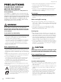
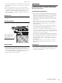
Make sure that the front
end of the table will
remain under the front
stabilizer legs.
PA_en_11 2/2

CS-R5 Owner’s Manual
6
Information
About copyrights
• Copying of commercially available musical data including but
not limited to MIDI data and/or audio data is strictly prohibited
except for your personal use.
About functions/data bundled with the product
• Even when the Power switches are in standby status (power
lamp is off), electricity is still flowing to the product at the
minimum level. When you are not using the product for a long
time, make sure you unplug the power cord from the wall AC
outlet.
• XLR-type connectors are wired as follows (IEC60268
standard): pin 1: ground, pin 2: hot (+), and pin 3: cold (–).
• Supply of this product does not convey a license nor imply
any right to distribute content created with this product in
revenue-generating broadcast systems (terrestrial, satellite,
cable and/or other distribution channels), streaming
applications (via Internet, intranets and/or other networks),
other content distribution systems (pay-audio or audio-on-
demand applications and the like) or on physical media
(compact discs, digital versatile discs, semiconductor chips,
hard drives, memory cards and the like). An independent
license for such use is required. For details, please visit
http://mp3licensing.com.
About this manual
• The illustrations and screens as shown in this manual are for
instructional purposes only.
• Yamaha Corporation make no representations or warranties
with regard to the use of the software and documentation and
cannot be held responsible for the results of the use of this
manual and the software.
• Windows is a registered trademark of Microsoft
®
Corporation
in the United States and other countries.
• Apple, Mac, and iPad are trademarks of Apple Inc., registered
in the U.S. and other countries.
• The company names and product names in this manual are
the trademarks or registered trademarks of their respective
companies.
• Software may be revised and updated without prior notice.
About disposal
• This product contains recyclable components.
When disposing of this product, please contact the
appropriate local authorities.
Yamaha cannot be held responsible for damage caused by
improper use or modifications to the product, or data that is
lost or destroyed.

CS-R5 Owner’s Manual
7
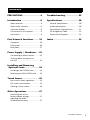
PRECAUTIONS...........................4
Introduction ............................8
About manuals.................................. 8
About utility software........................ 9
Firmware updates ............................. 9
Conventions in this manual............... 9
Accessories........................................ 9
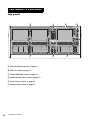
Part Names & Functions ........10
Top panel ....................................... 10
Front panel ..................................... 20
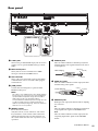
Rear panel....................................... 21
Power Supply / Shutdown.....23
Connecting to power sources.......... 23
Shutting down the power to
the unit........................................... 23
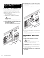
Installing and Removing
Optional Cards .....................24
Installing a Mini-YGDAI card ........... 24
Removing the Mini-YGDAI card....... 24
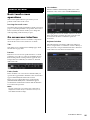
Touch Screen .........................25
Basic touch screen operations ......... 25
On-screen user interface.................. 25
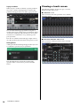
Viewing a touch screen ................... 26
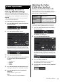
Other Operations...................27
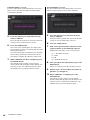
Initializing the unit to
factory default settings.................... 27
Adjusting the faders
(Calibration function)...................... 27
Troubleshooting ....................29
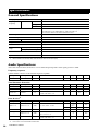
Specifications ........................30
General Specifications ..................... 30
Audio Specifications ........................ 30
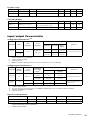
Input/output Characteristics............ 31
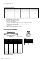
Pin Assignment Table ...................... 32
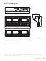
Dimensional Diagrams .................... 33
Index......................................34
Contents

CS-R5 Owner’s Manual
8
Thank you for purchasing the Yamaha Control Surface
CS-R5.
The CS-R5 is a control surface dedicated to the Yamaha
RIVAGE PM5 series digital mixing system. This manual
provides information regarding the basic functions and
operations for mixing engineers and technical personnel
at audio installation companies.
In order to take full advantage of this system's superior
functionality and enjoy years of trouble-free use, please
read this manual before you use the product. After you
have read the manual, keep it in a safe place for future
reference.
About manuals
•CS-R5 Owner’s Manual (this book)
This guide also explains part names and functions on
the panels of the CS-R5.
•RIVAGE PM series Operation Manual
The Operation Manual provides detailed explanations
of all screens and functions, and includes step-by-step
procedures and system set-up process to help you
operate the RIVAGE PM series.
• RIVAGE PM Editor Installation Guide
This guide describes how to install the RIVAGE PM
Editor.
• RIVAGE PM StageMix User Guide
This guide describes an iPad application that enables
you to control the RIVAGE PM series system
wirelessly.
Using the PDF manual
The RIVAGE PM series Operation Manual and the
Editor Installation Guide are electronic files in PDF
format. You can read this book on a computer. Use
Acrobat Reader to read this book on screen, search for
words very quickly, print specific pages, or click links
to display sections of special interest. The ability to
search for words, or to follow links directly to relevant
sections in the document, are helpful attributes of this
electronic file format. We encourage you to take
advantage of these benefits.
You can download the latest Acrobat Reader
application from the website listed below.
http://www.adobe.com/
All manuals can be downloaded from the Yamaha website.
If necessary, you can review updated manual information,
which is always posted in the Yamaha website.
http://download.yamaha.com/
Yama ha E c o- L a bel
Yamaha Eco-Label is a mark that certifies
products of high environmental
performance.
Introduction

CS-R5 Owner’s Manual
9
About utility software
The RIVAGE PM series can be used with a variety of
utility software.
•RIVAGE PM Editor
This application software enables you to access the
same functions that are available on the control
surface. You can use your computer to perform off-line
editing by preparing the RIVAGE PM series settings in
advance, and to monitor and adjust those settings (on-
line monitoring/operation).
•RIVAGE PM StageMix
StageMix enables you to use your iPad to wirelessly
control the parameters of your Yamaha RIVAGE PM
series digital mixing console. StageMix offers the
sound engineer (who is away from the system) the
freedom to control parameters remotely, while
listening to the results from the vantage point of the
performers.
Information on this software application is available on
the Yamaha Pro Audio global website:
http://www.yamahaproaudio.com/
For information regarding how to download or install
Editor or StageMix, as well as their various setting
details, please refer to the website listed above or to the
Installation Guide attached to the downloaded
software program.
Firmware updates
You can update the unit firmware to improve operations,
add functions, and correct possible malfunctions.
Details on updating the firmware are available on the
following Yamaha Pro Audio global website:
http://www.yamahaproaudio.com/
For information on updating and setting up the unit,
please refer to the firmware update guide available on the
website.
Conventions in this manual
In this manual, switch-type controllers on the panel are
called “keys.” Control knobs on the panel are called
“knobs.” Some knobs rotate from a minimum value to a
maximum value, while others rotate endlessly.
Virtual buttons displayed on the screen are called
“buttons,” and virtual knobs are called “knobs.”
Controls located on the panel are enclosed in square
brackets [ ] (e.g., [CUE] key) to distinguish them from
virtual buttons and knobs displayed on screen. For certain
controls, the name of the section appears before the
brackets (e.g., SCENE MEMORY [STORE] key).
Accessories
•AC power cord × 2
(Multiple AC power cords which have different kinds
of plug shapes may be included depending on the
region.)
•Dust cover
•Nuendo Live (DAW software)
•Owner’s Manual (this book)


CS-R5 Owner’s Manual
11
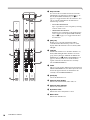
A Selected Channel section
This section enables you to adjust parameters for the selected channel.
The knobs in the Selected Channel section feature the Touch Sense function.
DYNAMICS 1/2
This section enables you to select Dynamics 1 or 2, and make detailed settings. You can also view the input level and the gain
reduction of selected Dynamics.
DYNAMICS [1]/[2] keys
These enable selection of Dynamics 1 or 2.
DYNAMICS 1/2 IN LEDs
Indicates the input level of selected Dynamics.
DYNAMICS 1/2 GR LEDs
Indicates the gain reduction amount of selected
Dynamics.
DYNAMICS 1/2 [ON] key
Switches Dynamics on or off.
– DYNAMICS 1/2 setting knobs
These knobs enable you to make detailed settings for Dynamics 1 or 2. The available knob functions vary depending on the
type of selected Dynamics. For more information regarding the type of Dynamics, please refer to the RIVAGE PM series
Operation Manual.
Dynamics processor type
GATE/DUCKING THRESHOLD RANGE — ATTACK HOLD DECAY
COMP/EXPANDER THRESHOLD RATIO OUTGAIN ATTACK RELEASE KNEE
DE-ESSER THRESHOLD FREQ Q — — TYPE

CS-R5 Owner’s Manual
12
GAIN, HPF, PAN, Fn
[GAIN] knob
Controls the analog gain or digital gain.
HPF [ON] key
Switches the HPF on or off.
[HPF] knob
Adjusts the HPF cutoff frequency.
[PAN] knob
Adjusts the panning of the signal sent to the
stereo buses.
[Fn] (Function) knob
Adjusts the specified parameter.
EQUALIZER
EQUALIZER [ON] key
Switches EQ on or off.
EQUALIZER [Q] knobs
Specify the Q value.
EQUALIZER [GAIN] knobs
Adjust the gain.
EQUALIZER [FREQUENCY] knobs
Adjust the frequency.

CS-R5 Owner’s Manual
13
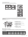
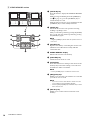
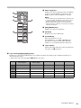
B UTILITY section
POWER Indicator
Lights when AC power to the unit is ON. If both
power switches A and B are turned on, this indicator
will light green. If either power switch A or B is
turned on, it will light red. If the RIVAGE PM5
system is not started, it will light orange.
USB port
Enables you to connect a USB device (such as a
mouse, keyboard, or USB flash drive). Use a USB
flash drive to store the system’s internal data and to
load the stored data into the system.
■ Supported USB ash drive format
The FAT16 and FAT32 formats are supported.
■ Write Protection
Some USB flash drives feature write protection that
prevents data from being erased inadvertently.
If your USB flash drive contains important data, we
suggest that you use write protection to prevent
accidental erasure.
On the other hand, you will need to make sure that
your USB flash drive’s write-protect setting is turned
off before you save data onto the USB flash drive.
For the latest information on which USB flash drives
can be used with the system, visit the Yamaha Pro
Audio global website at:
http://www.yamahaproaudio.com/
NOTICE
Do not remove the USB flash drive from the USB
connector or turn off the power to the unit while the unit is
accessing data, e.g., saving, loading or deleting data.
Doing so may damage your flash drive, or may damage the
data in the unit or on your media device.
RECORDING port
Enables you to connect a USB flash drive to record
and play back audio files. Supported file formats
include WAV and MP3.
For the latest information on what USB flash drives
can be used with the system, visit the Yamaha Pro
Audio global website at:
http://www.yamahaproaudio.com/
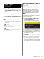
[SYSTEM] key
Press this key to display information about the
RIVAGE PM5 system on the touch screens.
Press and hold down the key for two seconds or
longer to shut down the control section of the console
(see page 23). Be sure to shut down before turning off
the power switches.
TALKBACK [ON] key
Switches the Talkback function on or off.
TALKBACK [LEVEL] knob
Adjusts the Talkback input level.
MONITOR A/B [LEVEL] knobs
Adjust the output level of the monitoring signals.

CS-R5 Owner’s Manual
14
C SCENE MEMORY section
[OVERLAY] key
Press this button to display the OVERLAY SETTING
screen.
While pressing and holding down the [SHIFT] key
(see on page 17), press the [OVERLAY] key to
switch Overlay on or off.
While Overlay is turned on, press and hold down the
[OVERLAY] key to enter Overlay edit mode.
[UNDO] key
Cancels the most recent scene operation of storing,
recalling or updating a scene.
After you cancel the operation by pressing the [UNDO]
key, you can “redo” the canceled operation by pressing
the [UNDO] key again.
NOTE
Using the [UNDO] key will not undo an operation to store a
new scene.
[UPDATE] key
Updates scene data by overwriting the current scene
(that has been recalled most recently) with the
current mix data.
SCENE MEMORY display
Indicates the selected scene memory.
[PREVIEW] key
Switches Preview mode on or off.
[STORE] key
Stores the current scene settings to the selected scene
memory. If you select the existing scene as the store
destination, it will be overwritten.
NOTE
Use the [UPDATE] key to overwrite the current scene.
[INC]/[DEC] keys
Enable you to select the scene number of a scene that
you want to store or recall.
NOTE
• If you select a scene other than the current scene, the
scene number on the LCD display will flash.
• Press the [INC] and [DEC] keys simultaneously to return
to the current scene.
[RECALL] key
Enables you to recall a selected scene from scene
memory.

CS-R5 Owner’s Manual
15
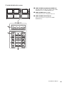
D USER DEFINED KEYS section
USER DEFINED [A]/[B]/[C]/[D] BANK keys
Select the bank ([A], [B], [C], or [D]) for the USER
DEFINED knobs or USER DEFINED keys.
USER DEFINED keys [1]–[12]
Control the functions as assigned by the user.
USER DEFINED KEYS displays
Indicate the functions assigned to the USER
DEFINED keys.

CS-R5 Owner’s Manual
16
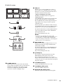
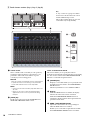
E Touch Screen section (Bay L, Bay C, Bay R)
Touch screen
This is a multi-touch screen that you can operate by
touching it with your finger to select menus or set
parameters. The touch screen will not respond
correctly if you are wearing gloves.
NOTICE
Never use a sharp or pointed object such as your fingernail
to operate the touch screens. Doing so may scratch the
screens and render the touch screens inoperable.
NOTE
• If the touch screens become dirty, wipe them with a soft
dry cloth.
• Before use, be sure to remove the transparent film
applied to the touch screens to protect them during
transport.
[VIEW] key
Recalls and toggles between the OVERVIEW and
SELECTED CHANNEL VIEW screens.
SEND / USER DEFINED KNOB
This section enables you to specify the send bus
destination, and adjust the send level for the corresponding
bus. You can also switch to the USER DEFINED KNOB
function to control the assigned function.
[ASSIGN] key
Displays a screen that enables you to specify the send
destination bus and switch to the USER DEFINED
KNOB function.
The factory default bus is set to SEND TO MIX 1.
Display
While the SEND function is enabled, the display
indicates the selected bus and its send level.
While the USER DEFINED KNOB function is
enabled, the display indicates the assigned function
parameter and its value.
SEND / USER DEFINED knob
Adjusts the send level for the corresponding bus
while the SEND function is enabled.
Enables you to control the assigned function while
the USER DEFINED KNOB function is enabled.
Bay L Bay C Bay R
Bay
A “bay” consists of a group of 12 faders
located across the Touch Screen section
and the Channel Strip section.
The CS-R5 contains three bays. You can
control these bays independently.

CS-R5 Owner’s Manual
17
F Channel Strip section (Bay L, Bay C, Bay R)
[ENCODER ASSIGN] key
Displays a screen that enables you to switch between
the Screen Encoder function and the Channel
Encoder function. You can use only the Channel
Encoder function for channel strips A and B.
[HOME] key
Recalls a group of settings for the bay. Press and hold
down this key to store the following settings:
• Layers and current screen data
• Selected channel/parameters on screen
PIN indicator
Lights up when the Pinning function for the
[TOUCH AND TURN] knob is turned on.
(This feature will be supported by a future update.)
[TOUCH AND TURN] knob
Controls the parameter of the knob you selected by
touching the touch screen.
[SHIFT] key
Combine with another key to perform a certain
function.
The following table shows an example of using the
[SHIFT] key combined with another key. For more
information, please refer to the RIVAGE PM series
Operation Manual.
[SENDS ON FADER] key
Turns SENDS ON FADER mode on and off. While
SENDS ON FADER mode is enabled, the input faders
will control the send levels of the corresponding
buses.
Procedure Function
Press and hold down the
[SHIFT] key and press
multiple [SEL] keys.
Temporary link.
Controlling the parameter of
multiple channels
simultaneously.

CS-R5 Owner’s Manual
18
Strip encoder
You can use the Screen Encoder function and the
Channel Encoder function for channel strips 1–12.
Use the [ENCODER ASSIGN] key (see on
page 17) to toggle between these two functions. You
can use only the Channel Encoder function for
channel strips A and B.
• Screen Encoder function:
Up to 12 parameters can be assigned by selecting
controls on the screen.
• Channel Encoder function:
Parameters for 12 channels on the channel strips
can be assigned. Use the [ENCODER ASSIGN]
key (see on page 17) to toggle between these
two functions.
[SEL] key
Enables you to select the channel that will be
controlled in the Channel Strip section or on the
display. When the channel is selected, the key LED
will light.
[ON] key
Switches the channel on or off. If the channel is on,
the key LED will light. If the channel is in a mute
group, the key indicator will flash. In SENDS ON
FADER mode (see [SENDS ON FADER] key on
page 17), this key works as an on/off switch for
signals sent from each channel to the currently-
selected MIX/MATRIX bus.
Fader
This is a touch-sensitive 100 mm motorized fader. In
SENDS ON FADER mode, this fader adjusts the send
level of the signal sent from each channel to the
currently-selected MIX/MATRIX bus.
[CUE] key
Selects the channel for cue.
Channel name display
Indicates the channel name, fader value, etc.
Channel color indicator
Indicates the channel color.
Dynamics LEDs
Indicate the status of Dynamics 1 and 2.
Meter LEDs
Indicate the channel level.

CS-R5 Owner’s Manual
19
INPUT [1]/[2] keys
Enable you to select an input layer. Press the INPUT
[1] key to select the INPUT 1-72 layer. Press the
INPUT [2] key to select the INPUT 73-144 layer.
NOTE
Press the INPUT [1] key and INPUT [2] key simultaneously
to select the INPUT 145-288 layer. Press these two keys
simultaneously again to select the INPUT 1-144 layer.
When the INPUT 145-288 layer is selected, these key
indicators light up in a different color than when the INPUT
1-144 layer is selected.
[MIX]/[MATRIX] keys
Enable you to select an output layer.
[DCA] key
Enables you to select a DCA bank.
[CUSTOM] key
Turns Custom mode on or off.
Use the INPUT [1], [2], [MIX], [MATRIX], and
[DCA] keys to select a Custom bank. The bank
numbers (1–5) are labeled adjacent to these keys.
Layer displays
Indicates the name of the layer selected via the Layer
select keys (see on page 19).
Layer select [A]/[B]/[C]/[D]/[E]/[F] keys
Enable you to select a layer. Different layers are recalled to the faders depending on the combination of the keys, as
shown in the table below:
(* Please refer to the Note regarding the INPUT [1]/[2] keys.)
Key
INPUT [1] /
INPUT [1]+[2]*
INPUT [2] /
INPUT [1]+[2]*
[MIX] [MATRIX] [DCA]
[A] Input 1-12 / 145-156* Input 73-84 / 217-228* MIX 1-12 MATRIX 1-12 DCA 1-12
[B] Input 13-24 / 157-168* Input 85-96 / 229-240* MIX 13-24 MATRIX 13-24 DCA 13-24
[C] Input 25-36 / 169-180* Input 97-108 / 241-252* MIX 25-36 MATRIX 25-36 —
[D] Input 37-48 / 181-192* Input 109-120 / 253-264* MIX 37-48 STEREO —
[E] Input 49-60 / 193-204* Input 121-132 / 265-276* MIX 49-60 CUE/MONITOR —
[F] Input 61-72 / 205-216* Input 133-144 / 277-288* MIX 61-72 — —

CS-R5 Owner’s Manual
20
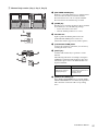
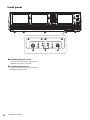
Front panel
PHONES A/B [LEVEL] knobs
Adjust the level of the signal output from the
PHONES output jacks respectively.
PHONES A/B output jacks
These are headphone jacks for monitoring the
MONITOR or CUE signal.
Strona się ładuje...
Strona się ładuje...
Strona się ładuje...
Strona się ładuje...
Strona się ładuje...
Strona się ładuje...
Strona się ładuje...
Strona się ładuje...
Strona się ładuje...
Strona się ładuje...
Strona się ładuje...
Strona się ładuje...
Strona się ładuje...
Strona się ładuje...
Strona się ładuje...
Strona się ładuje...
-
 1
1
-
 2
2
-
 3
3
-
 4
4
-
 5
5
-
 6
6
-
 7
7
-
 8
8
-
 9
9
-
 10
10
-
 11
11
-
 12
12
-
 13
13
-
 14
14
-
 15
15
-
 16
16
-
 17
17
-
 18
18
-
 19
19
-
 20
20
-
 21
21
-
 22
22
-
 23
23
-
 24
24
-
 25
25
-
 26
26
-
 27
27
-
 28
28
-
 29
29
-
 30
30
-
 31
31
-
 32
32
-
 33
33
-
 34
34
-
 35
35
-
 36
36


Yamaha CS-R5 Instrukcja obsługi
- Kategoria
- Kontrolery DJ
- Typ
- Instrukcja obsługi
w innych językach
- čeština: Yamaha CS-R5 Návod k obsluze
- español: Yamaha CS-R5 El manual del propietario
- italiano: Yamaha CS-R5 Manuale del proprietario
- Deutsch: Yamaha CS-R5 Bedienungsanleitung
- português: Yamaha CS-R5 Manual do proprietário
- français: Yamaha CS-R5 Le manuel du propriétaire
- English: Yamaha CS-R5 Owner's manual
- dansk: Yamaha CS-R5 Brugervejledning
- Nederlands: Yamaha CS-R5 de handleiding
- română: Yamaha CS-R5 Manualul proprietarului
Powiązane artykuły
-
Yamaha CS-R3 Instrukcja obsługi
-
Yamaha V3 Instrukcja obsługi
-
-
-
-
-
-
Yamaha CL5 Instrukcja obsługi
-
Yamaha V1 Instrukcja obsługi
-