Gronomics CCPC 45-45 Chicken Coop Assembly Instructions
- Typ
- Assembly Instructions

East Bethel, MN USA 763-753-7374
Continued
1
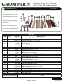
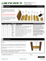
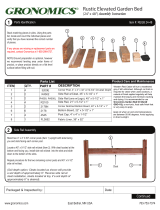
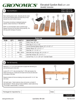
Parts Identifi cation Box 1
Remove contents from Box 1 of 2.
Stack matching pieces in piles. Using the
parts list, locate and count the individual
pieces and verify that you have received
the correct number of pieces.
If any pieces are missing or replacement
parts are required, contact Gronomics at
1-855-299-6727.
NOTE: It is recommended to place a
protective layer between the ground and
the pieces during assembly. This will help
prevent damage to the pieces.
2
13
13
14
14
15
15
18
18
19
19
3
7
4
5
6
Box 1 of 2
ITEM QTY. PART # DESCRIPTION
1 2 NASR11 Nesting Angle Side Rail, 11-1/2” x 4-1/4”
2 4 NSR11.5 Nesting Side Rail, 11-1/2” x 5-1/2”
3 4 NSR12 Nest Side Rail, 11-5/8” x 4”
44
54
8 -3/4 Screw, #8 x 3/4”
R48-234ZY Screw, GRK #8 x 2
6 1 Ramp Hook
7 2 Nesting Post, 12-3/8” x 1-7/8”
84 Nesting Post, 15-1/4” x 1-7/8”
9 2
Rhook
NP12
NP15
CRP37 Rear Post, 36-3/4” x 3-1/4”
10 2 4078N Bottom Notched Board, 40-7/8” x 5-1/4”
11 2 4078 Bottom Board, 40-7/8” x 5-1/4”
12 2
13 6
14 1
4078R Bottom Ripped Board, 40-7/8” x 3-5/8”
CSB40 Coop Side Board, 40” x 5-3/8”
FCSR40 Front Cleat Side Rail, (w/Logo), 40” x 4”
15 1 BCSR40 Back Cleat Side Rail, 40” x 4”
16 1 Angled Coop Side RH, 12-1/2 ” x 14-5/8”
17 1 Angled Coop Side LH, 12-12” x 14-5/8”
18 1 Ramp, 39-3/4” x 11”
19 1 Roost Rod, 40-3/4” x 1-1/4”
20 2
ACS12RH
ACS12LH
RAMP
CCRR41
CCRRH Roost Rod Holder
Chicken Coop Pet Cottage
45"W x 45"D x 48”H Assembly Instruction
CCPC 45-45
12
12
10
10
11
11
9
8
Packaged & Inspected by: Date:
1
16
16
17
17
20
20
Torx® T15
Phillips

East Bethel, MN USA 763-753-7374
Continued
2
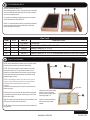
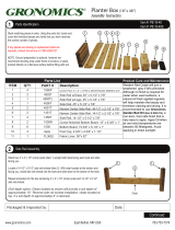
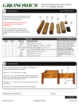
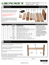
Parts Identifi cation Box 2
Remove contents from Box 2 of 2.
Stack matching pieces in piles. Using the parts list, locate and
count the individual pieces and verify that you have received
the correct number of pieces.
If any pieces are missing or replacement parts are required,
contact Gronomics at 1-855-299-6727.
NOTE: It is recommended to place a protective layer between
the ground and the pieces during assembly. This will help
prevent damage to the pieces.
Box 2 of 2
ITEM QTY. PART # DESCRIPTION
21 1 CCFoldLid Folding Lid
22 1 SD4021 Screen Panel, W/Door 40” x 21-1/2”
23 3 SS4021 Screen Panel, 40” x 21-1/2”
24 2 CFP48 Front Post, 47-3/4” x 3-1/4”
25 1 SW4021 Screen Panel, 40” x 21-1/2” w/Winterized Window Cover (Not Shown)
21
21
22
22
23
23
24
24
3
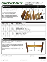
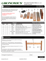
Screen Panel Assembly
NOTE: Always assemble the chicken coop on a level surface
and keep posts and parts square when assembling.
NOTE: The chicken coop pet cottage contains one screen
panel w/door (Item 22). The screen panel w/door can be
located on any side desired of the chicken coop pet cottage,
choose which side to locate the screen panel w/door when
performing steps 3 thru 5.
NOTE: If assembling a chicken coop with a run kit, refer to
chicken coop run kit instructions step 2 for the blank panel
installation, before proceeding with chicken coop
assembly.
Position a screen panel (Item 22 or Item 23) with the screw
heads facing you.
Position the 47-3/4” posts (Item 24) with the fl at end (straight
cut) towards the ground and with a slot facing you and a slot
facing left and right.
Align the screen panel tabs with the post slots and slide a post
down onto the screen panel on each end.
NOTE: Make sure the screen panel tabs are fully inserted into
the post slots.
23
23
24
24
24
24
22
22
Locate the screen panel w/door
(Item 22) on any side of the
chicken coop pet cottage when
performing steps 3 - 5.
Install the screen panel w/door
with the door latch located
upward.
Door Latch

East Bethel, MN USA 763-753-7374
Continued
23
23
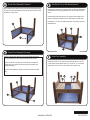
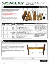
4
Screen Panel Assembly Continued
Align a screen panel (Item 22 or Item 23) with the screw heads facing
in. Align the screen panel tabs with the post slots and slide the screen
panel down on both posts.
23
23
5
Screen Panel Assembly Continued
Position a screen panel (Item 22 or 23) (screw heads facing away
from you) between the two previously installed screen panels.
Position the 36-3/4” posts (Item 9) with the fl at end (straight cut)
towards the ground, make sure the top of the post tapered cut is
slopped towards you.
Align the screen panel tabs with the post slots and slide the posts
down.
23
23
6
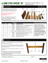
Side Rail And Coop Side Board Assembly
Install the front cleat side rail (w/Logo) (Item 14) (with the cleat located
at the bottom and facing in) between the two 47-3/4” posts and slide
down.
Install the back cleat side rail (Item 15) (with the cleat located at the
bottom and facing in) between the two 36-3/4”posts and slide down.
Install four 40” x 5-3/8” coop side boards (Item 13) between the posts
and slide down.
15
15
7
Roost Floor Assembly
Install the 40-7/8” x 5-1/4” bottom notched boards (Item 10), 40-7/8”
x 3-5/8” bottom ripped boards (Item 12), and 40-7/8” x 5-1/4” bottom
boards (Item 11) as shown on each side of the chicken coop.
10
10
10
10
12
12
12
12
11
11
11
11
14
14
13
13
13
13
9
9

East Bethel, MN USA 763-753-7374
Continued
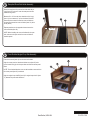
Place the ramp (Item 18) onto the front cleat side rail (w/
Logo) (Item 14) as shown. Lower the ramp end with the
handle to the ground.
Measure 8” to 10” from the front cleat side rail (w/ Logo)
(Item 14), then measure 6” up from the bottom notched
board and place a mark. Center the roost rod holder on
the mark and secure the roost rod holder (Item 19) with a
screw (Item 4).
Repeat procedure on the opposite side and secure the
roost rod holder (Item 20).
NOTE: When installing the roost rod holder with the open
end, make sure the open end of the roost rod holder is
located upward.
8
Ramp And Roost Rod Holder Assembly
18
18
20
20
14
14
20
20
8” to 10”
6”
Roost Rod And Angled Coop Side Assembly
Place the roost rod (Item 19) into the roost rod holders.
Align the screen panel w/ winterized window cover (Item 25) tabs
(screw heads facing in) with the post slots and slide the screen panel
down.
NOTE: The winterized window cover can be installed or removed from
the screen panel (Item 25) as desired.
Align the angled coop side RH (Item 16) & angled coop side LH (Item
17) between the posts and slide down.
25
25
17
17
16
16
19
19
9

East Bethel, MN USA 763-753-7374
Continued
Place the nesting boxes as shown and install four #8 x
2-3/4”screws (Item 5) from the outside of the coop into the
center of the nesting box posts.
Nesting Box Assembly
Assemble the nesting boxes as shown.
12
12
Nesting Box Assembly Continued
13
13
1
1
2
8
8
8
8
3
3
3
3
5
55
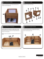
Using the handle on the ramp (Item 18), raise the ramp up until the
ramp is level with the fl oor. Place the ramp hook (Item 6) onto the
ramp handle and secure the ramp hook to the coop side board with
two #8 x 3/4” screws (Item 4).
NOTE The ramp can be positioned in the raised or lowered position as
desired.
Coop Side Board Assembly
Install the two remaining 40’ x 5-3/8” coop side boards (Item 13)
between the posts and slide down.
10
10
13
13
Ramp And Ramp Hook Assembly
11
11
18
18
6
77
4

East Bethel, MN USA 763-753-7374
NOTE: Make sure the folding lid is
positioned as shown (far right) before
placing onto the chicken coop. The
open end (no trim) of the folding lid
located at the bottom, to allow water
to run off.
Install the folding lid (Item 21) onto
the chicken coop as shown. Make
sure the folding lid notches are
aligned and positioned onto the
chicken coop screen panel and coop
side board.
Close the folding lid.
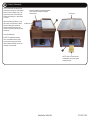
NOTE: The winterized window
cover is installed onto the upper
screen panel to help protect pets
from inclement weather, but can be
removed in the summer.
Folding Lid Assembly
21
21
22
22
Lid Notches
14
14
Folding Lid
If desired, install the winterized window
cover onto the outside of the upper
screen panel.
NOTE: Open or close the door
as desired on the screen panel
w/door (Item 22).
-
 1
1
-
 2
2
-
 3
3
-
 4
4
-
 5
5
-
 6
6


Gronomics CCPC 45-45 Chicken Coop Assembly Instructions
- Typ
- Assembly Instructions
w innych językach
- English: Gronomics CCPC 45-45 Chicken Coop
Powiązane artykuły
-
 Gronomics PB 18-18 Instrukcja obsługi
-
 Gronomics PB 18-48 Assembly Instructions
-
 Gronomics REGB 24-48 Assembly Instructions
-
 Gronomics MEGB 34-34 EXTS Instrukcja obsługi
-
 Gronomics EGBD 24-48S Instrukcja obsługi
-
 Gronomics EGBD 24-48 Assembly Instructions
-
 Gronomics EGB 24-48 Instrukcja obsługi
-
 Gronomics EGB 34-48 Instrukcja obsługi
-
 Gronomics EGB 24-48 Assembly Instructions
-
 Gronomics EGB 18-34S Instrukcja obsługi


