Yamaha TX4n Instrukcja obsługi
- Kategoria
- Sprzęt muzyczny
- Typ
- Instrukcja obsługi
Niniejsza instrukcja jest również odpowiednia dla

Reference Manual
EN

TX6n/5n/4n Reference Manual
2
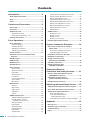
Contents
Introduction............................................. 3
About the documentation.......................................... 3
Setup ...........................................................................3
Terms........................................................................... 4
Controls and Connectors ...................... 5
Front Panel.................................................................. 5
Rear Panel................................................................... 8
Optional I/O cards ......................................................9
Supported I/O cards ...............................................9
Removing and installing a card............................. 10
Cleaning the air filters.............................................. 11
Panel Operations.................................. 12
Basic Operations...................................................... 12
About the Display.................................................. 12
Switching Screens ................................................ 12
Editing the Parameters ......................................... 12
Adjusting the Attenuation......................................12
Screen Structure ......................................................13
Operations that can be Performed from
the Panel ................................................................ 14
Alert Messages ......................................................... 15
HOME Screen............................................................ 15
METER Screen.......................................................... 16
SETTING Screen....................................................... 17
UTILITY Screen......................................................... 19
Device Setup ........................................................ 19
Word Clock Setup................................................. 20
Information............................................................ 21
Network Setup ...................................................... 21
LCD Setup ............................................................ 22
Front Panel Operation........................................... 22
Scene Setup ......................................................... 23
Misc Setup ............................................................ 24
MENU Screen............................................................ 24
General ................................................................. 25
Signal Path ........................................................... 26
Signal Chain ......................................................... 27
Calibration............................................................. 28
Limiter ................................................................... 29
SIGNAL PATH Screen .............................................. 30
SIGNAL PATH Block Diagrams............................. 30
Recalling library settings
(Speaker Processor only).................................. 32
Slot Input Router................................................... 33
Input On/Off .......................................................... 33
4x4 Matrix Mixer ................................................... 33
8Band Input EQ .................................................... 34
Input Delay............................................................ 34
Oscillator Mix ........................................................ 35
X-Over Input Level (Speaker Processor) ..............35
X-Over Polarity (Speaker Processor)....................35
X-Over (Speaker Processor)................................. 36
Output Delay (Speaker Processor) .......................37
6Band Output EQ (Speaker Processor)................37
Output Level (Speaker Processor)........................ 38
Mute On/Off (Speaker Processor) ........................38
Limiter (Speaker Processor) ................................. 39
Output Router .......................................................39
SCENE Screen ..........................................................40
Recalling a scene .................................................40
Storing a scene.....................................................41
Editing a scene .....................................................42
Erasing a scene (Clear) ........................................ 42
Initializing the internal memory............................... 43
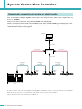
System Connection Examples ............ 44
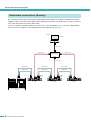
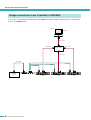
Daisy-chain connection via analog or
digital audio ........................................................... 44
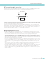
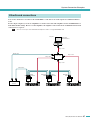
Thru-output for digital connections........................45
Regarding digital connections...............................45
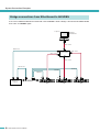
Redundant connections (Backup) ..........................46
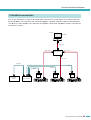
EtherSound connections ......................................... 47
Bridge connections from
EtherSound to AES/EBU ...................................... 48
CobraNet connections .............................................49
Bridge connections from
CobraNet to AES/EBU........................................... 50
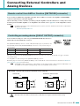
Connecting External
Controllers and Analog Devices ......... 51
Remote control from AMX or Crestron
([NETWORK] connector) ...................................... 51
Controlling an analog device
([FAULT OUTPUT] connector) ............................. 51
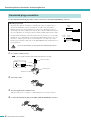
Euroblock plug connection .....................................52
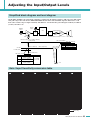
Adjusting the Input/Output Levels ...... 53
Simplified block diagram and level diagram.......... 53
Gain / Input Sensitivity conversion table ...............53
Adjusting the input/output levels............................ 54
Basic level adjustment ..........................................54
Level adjustments between
TX6n/TX5n/TX4n units ...................................... 54
Level adjustments between analog and digital .....54
Appendix ............................................... 55
Message List ............................................................. 55
Alert Message List (Excerpt) ...................................56
Troubleshooting .......................................................57
Index ..........................................................................58

TX6n/5n/4n Reference Manual
3
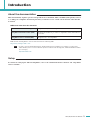
Introduction
About the documentation
This manual mainly explains operation and specifications for the TX6n, TX5n, and TX4n (subsequently referred
to as TXn) power amplifiers. When using the TXn, you will also need to consult various manuals other than this
document.
● Manuals other than this document
PDF manuals and Amp Editor can be downloaded from the following URL.
http://www.yamahaproaudio.com/
• In order to view the downloaded manuals, Adobe Reader must be installed in your computer. If you don’t have
Adobe Reader, please access the Adobe Corporation’s website at the following URL, and download Adobe Reader
(free of charge).
http://www.adobe.com/
Setup
For details on setting up the TXn and Amp Editor, refer to the “TX6n/5n/4n Owner’s Manual” and “Amp Editor
Owner’s Manual.”
TX6n/5n/4n Owner’s Manual (printed) Explains mainly the initial setup.
Amp Editor Installation Guide (PDF) Explains the installation procedure for Amp Editor and the uninstallation
procedure.
Amp Editor Owner’s Manual (PDF) Explains how to use Amp Editor.
NOTE

TX6n/5n/4n Reference Manual
4
Introduction
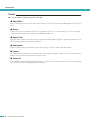
Terms
This section explains terminology specific to the TXn.
■ Amp Editor
This is computer application software. This software allows you to monitor and control the TXn amplifiers from your com-
puter.
■ Scene
Settings such as power-on/standby or mute for each amplifier are called a “scene.” By recalling a scene, the saved settings
can be immediately applied to the amplifiers. Each TXn unit has 50 scenes.
■ Signal Path
This is the audio signal processing functionality provided by the internal DSP. Components organized into modules accord-
ing to their functionality are placed in the signal path.
■ Component
These are modules in the signal path that organize audio signal processing according to their functionality.
■ Library
The settings of all Speaker Processor components can be saved together in a library. A library can be saved only from Amp
Editor, but can be recalled from the unit’s front panel as well.
■ Device ID
This is an ID for uniquely identifying a TXn unit within a network. In order to allow monitoring and control from Amp Edi-
tor, you must specify non-conflicting IDs within a workspace.

TX6n/5n/4n Reference Manual
5
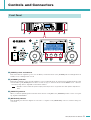
Controls and Connectors
q [POWER] switch and indicator
This switch turns the amplifier’s power on or off. When you turn this switch on, the [POWER] indicator will light white. In
Standby mode, it will light white as well.
w [STANDBY] indicator
This indicator will light orange when the amplifier’s power is in Standby mode. To switch between Standby/On modes, hold
down the TXn’s panel [HOME] button for three seconds or longer, or switch the mode from the MENU screen ➝ General
➝ Sensitivity/Amp Gain or Amp Editor’s Detail View window.
• Standby is a state in which the speaker output’s power amp section is off (operation other than speaker output will con-
tinue).
e [IDENTIFY] indicator
When you click the [Identify] button in the Tree View window of Amp Editor, the [IDENTIFY] indicator of the correspond-
ing amplifier will blink blue.
r [NETWORK] indicator
This will blink green when the amplifier is connected to a computer via the [NETWORK] connector, and data is being sent
or received.
Front Panel
!9 !9
e
r
u
t
w
i
!3 !3
i
oo
!0
!2
!1
!6 !7 !8
!5
q
y
q
!4
!0
!2
!1
@0@0
NOTE

TX6n/5n/4n Reference Manual
6
Controls and Connectors
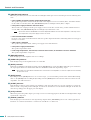
t [PROTECTION] indicator
When the protection system is active, this indicator will light red. The protection circuit will operate in the following situa-
tions.
• If the amplifier overheats and the output limiter operates
The speaker output will be attenuated if the heat sink of the amplifier section exceeds 80°C (80%), and will be muted if
the heat sink exceeds 90°C (90%). The [PROTECTION] indicator will light at 80°C (80%) or higher.
• If the power supply overheats and shuts-down
The fan will rotate at high speed if the power supply section exceeds 90°C, and the analog circuits will shut down if it
exceeds 100°C. The [PROTECTION] indicator will light only if shut-down occurs.
• The thermal meter in the METER screen and in Amp Editor indicates the heat sink temperature of the amp section.
The temperature of the power supply section is not shown.
• If the load falls below 0.5 ohms
If a short occurs and the load falls below 0.5 ohms, the speaker output will be muted, and muting will be cleared approx-
imately 1 second later.
• If DC output is detected
The speaker output will be muted, and the power supply section will shut down.
• If the power supply malfunctions
The speaker output will be muted.
• If ultra-high frequencies, overcurrent, excessive total current, or maximum current is detected
The speaker output will be compressed.
y [BRIDGE] indicator
This will light green if the amplifier mode is set to Bridge.
u [PARALLEL] indicator
This will light orange if the amplifier mode is set to Parallel.
i [MUTE] indicator
This indicator will light red if muting is turned on by the [MUTE] button or from Amp Editor. When the power is turned on,
the output signal will also be muted and the indicator will blink red until audio begins being output.
•Even if mute is off, this indicator will blink if Solo was turned on from Amp Editor, or when the output has been muted by
the protection circuit.
o [MUTE] button
By holding down the [MUTE] button for one second or longer, you can turn muting on/off for that channel. When muting
turns on, the [MUTE] indicator will light. By holding down the [MUTE] button when the Solo function is turned on from
Amp Editor, Solo will be defeated.
!0 [ALERT] indicator
This will light to indicate an alert related to the amplifier’s audio signal. If an alert for a specific channel has occurred, the
indicator of the corresponding channel will light; for other alerts, the indicators of both channels will light. At this time, the
alert message will appear in the upper part of the display.
!1 [CLIP] indicator
When the signal of the speaker output’s power amp section exceeds the clipping level, this indicator will light and the output
signal will be compressed.
!2 [SIGNAL] indicator
This will light green when the level of the signal being output from the [SPEAKERS] jack exceeds 1 Vrms (equivalent to
0.2 W into an 8 ohms load, 0.4 W into a 4 ohms load or 0.8 W into a 2 ohms load).
NOTE
NOTE

TX6n/5n/4n Reference Manual
7
Controls and Connectors
!3 Encoders A, B
When the display shows the attenuation meter, these encoders adjust the attenuation of channels A and B. If any other
screen is displayed, encoder A moves the cursor and encoder B modifies the parameter value.
• Only encoder A can be operated if you’re adjusting the attenuation when the amplifier mode is Bridge.
!4 Display
This shows the amplifier’s settings or a level meter. Refer to “Screen Structure” (page 13) for details.
• If the power supply is in Standby mode or if the LCD Setup’s Backlight setting is Auto OFF, the backlight will go dark if no
panel operation has been performed for ten seconds. It will light again when a panel operation is performed.
!5 Function buttons
These buttons move to the screen indicated above each button in the display. If a channel name (e.g., CH A, CH B) is
shown, this means that a parameter for that channel is displayed; press the corresponding function button to switch the
channel that is shown. These buttons may also operate in different ways depending on the screen shown in the display.
!6 [HOME] button
This accesses the HOME screen (page 15) in the display.
By holding down this button for three seconds or longer, you can switch the power between Standby and On modes. When
the confirmation message appears, press the [ENTER] button to switch the setting.
!7 [EXIT] button
By pressing this button when the display shows a screen other than the HOME screen, you can move to the screen of the
next highest level.
•To temporarily disable panel lock, simultaneously hold down the [HOME] button and [EXIT] button for three seconds or
longer.
• If you hold down this button for three seconds or longer in the HOME screen, the FAULT OUTPUT connector output will
be reset (NC and C will be connected).
!8 [ENTER] button
Use this to select a parameter or to finalize an edited parameter value. Depending on the screen shown in the display, this
button may also be used in other ways. If the parameter value is blinking, you must finalize the value by pressing this but-
ton.
• If you hold down this button for one second or longer in the HOME screen, the UTILITY screen Device Setup page (page
19) will appear.
!9 Air intakes
The amplifier uses forced-air cooling. The variable speed cooling fan draws air in from the front and exhausts it through the
rear. The cooling fan speed varies depending on the heat sink temperature: It operates at low speed when it is below 40 °C
(40%), increases in speed according to increases in temperature, and operates at high speed when temperature exceeds 60
°C (60%). If the power supply exceeds 90°C, the variable speed fan will operate at high speed regardless of the heat sink
temperature.
Please be sure that you do not block the air intakes or exhaust vents. Also, clean the filter elements regularly. If the air
intakes are clogged with dust or debris, the amplifier will overheat, which may result in the amplifier shutting down.
@0 Screw holes for handles
These four screw holes (four locations) are for the included handles. Fix the handles to the amplifier, using the included flat-
head screws.
NOTE
NOTE
NOTE
NOTE

TX6n/5n/4n Reference Manual
8
Controls and Connectors
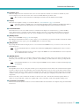
@1 [SPEAKERS] jacks
These are speaker output jacks.
• Speakon connectors : Speakon type cable plugs (Neutrik NL4) can be connected here.
• Five-way binding post connectors : Bare wires or Y plugs can be connected here.
• The five-way binding post connectors and Speakon connectors are internally connected in parallel. If you’re using both
simultaneously, make sure that the speaker impedance of each connector is 4–16 ohms (8–32 ohms in Bridge mode).
@2 Digital input/output connectors (I/O card slot)
An AES-IO card is installed as standard, allowing AES/EBU digital audio signals to be input and output.
• [IN] connector : This is an XLR-3-31 type balanced input connector for inputting two-channel digital audio sig-
nals.
• [OUT] connector : This is an XLR-3-32 type balanced output connector for outputting two-channel audio signals
processed by the internal DSP.
• [THRU] connector : This is an XLR-3-32 type balanced output connector that outputs the unprocessed signal received
at the [IN] connector. Even if the power is turned off, this connector will output the input signal
without any change (page 44). However, internal settings will be switched when the power is
switched on/off, causing the output signal to be muted for an instant.
• If desired, you can remove the AES-IO card and install a separately sold MY card. For details on the types of MY card
that can be used and how to install them, refer to “Optional I/O cards” (page 9).
• The removed AES-IO card cannot be installed and used in other devices.
•You must use a 110 ohm digital cable to make AES/EBU connections.
@3 Analog input/output connectors
These connectors input and output analog audio signals.
• [IN] connector : These are XLR-3-31 type input connectors for inputting ana-
log audio signals. The pin polarity is shown at right (IEC
60268).
• In Parallel mode and Bridge mode, only the signal of
channel A is output from the speaker output connector
by default. The channel B signal is not sent from the
speaker output, but the audio signal processed by the
internal DSP can be output from the digital output con-
nector.
• [THRU] connector : This is an XLR-3-32 type balanced output connector
that outputs the unprocessed analog signal received from
the [IN] connector.
Rear Panel
@2@1 @4
@5
@3@7 @6
NOTE
NOTE
Hot Ground
Cold
NOTE

TX6n/5n/4n Reference Manual
9
Controls and Connectors
@4 [NETWORK] connector
This is a 100BASE-TX/10BASE-T Ethernet connector. You can connect this to a computer so that the amplifier can be mon-
itored and controlled from Amp Editor. This also allows an external controller such as AMX or Crestron to be connected.
•To prevent electromagnetic interference, use an STP (Shielded Twisted Pair) cable for the [NETWORK] connector.
@5 [FAULT OUTPUT] connectors
This is a 3P Euroblock connector for controlling an external analog device when an abnormality occurs in the CPU or trig-
gered by the occurrence of a Fault event specified in Amp Editor. NC and C will be connected when the amplifier is operat-
ing normally; NO and C will be connected when a problem occurs (page 51). You can also reset this output from Amp
Editor.
A message will appear in the screen if a problem occurs. To reset the output, hold down the [EXIT] button for three seconds
or longer in the HOME screen.
@6 Power cable
Connect the plug of the power cable to an AC outlet of the correct voltage.
@7 Grounding screw
The AC power cord is a 3-wire type. If the AC outlet used is earthed (grounded), this device will be properly earthed as well.
Also, grounding the screw sometimes reduces hum and interference noise.
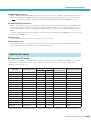
■ Supported I/O cards
You can remove the AES-IO card from the TXn’s rear panel, and install a separately sold MY (mini-YGDAI) card. As of Sep-
tember 2009, the following MY cards are supported. For the latest information, refer to the Yamaha pro audio website.
http://www.yamahaproaudio.com/
* When the card which supports Emulation mode is operating with the mode ON, the compatibility is the same as the emulated card.
Optional I/O cards
Card name Input/output format
Number of channels
Auto Scan Mode/
Redundant Backup
Input/output connector
Inputs Outputs
AES-IO (attached) AES/EBU 2 2 ✓ XLR-3-31, XLR-3-32
MY4-AD Analog input 4 — — XLR-3-31
MY8-AD24 Analog input 8 — — TRS phone
MY8-AD96 Analog input 8 — — D-sub 25-pin
MY4-DA Analog output — 4 — XLR-3-32
MY8-DA96 Analog output — 8 — D-sub 25-pin
MY8-ADDA96 Analog input/output 8 8 — Euroblock
MY8-AE AES/EBU 8 8 ✓ D-sub 25-pin
MY8-AE96 AES/EBU 8 8 ✓ D-sub 25-pin
MY8-AE96S AES/EBU 8 8 ✓ D-sub 25-pin
MY8-AEB AES/EBU 8 8 ✓ BNC
MY16-AE AES/EBU 16 16 ✓ D-sub 25-pin
MY16-CII CobraNet 16 16 — RJ-45
MY16-ES64 EtherSound 16 16 — * RJ-45
MY16-MD64 MADI 16 16 — * BNC, SC fiber
MY16-EX Expansion card 16 16 — * RJ-45
AVY16-ES
EtherSound made by
AuviTran Corp.
16 16 — RJ-45
NOTE

TX6n/5n/4n Reference Manual
10
Controls and Connectors
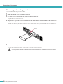
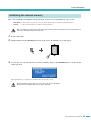
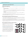
■ Removing and installing a card
To remove and install a card, proceed as follows.
1. Make sure that the power of the TXn is turned off.
2. Loosen the screws that fasten the slot, and remove the installed card.
Keep the removed card in a safe place.
3. Align the two edges of the card to be installed with the guide rails inside the slot, and insert the card into the
slot.
Push the card all the way into the slot so that the contacts of the card are correctly mated with the connector inside the slot.
4. Fasten the card using the screws attached to the card.
Be aware that malfunctions or faulty operation may occur if the card is not fastened.
•You must turn off the amplifier’s power switch before removing and installing a card. Otherwise, malfunctions or electric
shock may occur.
Guide rail
CAUTION

TX6n/5n/4n Reference Manual
11
Controls and Connectors
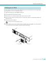
To ensure adequate cooling air intake, the filter elements must be cleaned when they have become clogged. Follow
the description below to clean each of the filter elements.
1. Make sure that the power to the amplifier is turned off.
2. Disconnect the power cable from the AC outlet.
3. Remove the two screws that fasten the front filter grill, and remove the grill.
4. Remove the filter element, and wash it in plain water. If the filter element is exceptionally dirty, mild deter-
gent may be used.
5. Dry the filter element completely.
•Never replace the filter element while it is still wet.
6. Replace the filter element on the air intake, hook the front filter grill on the amplifier, and secure it using the
screws. (The replacement part number of the filter element is WN311200.)
Cleaning the air filters
CAUTION
Filter elementFront filter grill

TX6n/5n/4n Reference Manual
12
Panel Operations
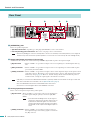
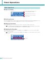
■ About the Display
■ Switching Screens
By pressing a function button you can move to the screen indicated above that button. By pressing the [HOME] button you can
move to the HOME screen. By pressing the [EXIT] button you can move to the screen one level above.
■ Editing the Parameters
Use encoders A and B to move to the parameter that you want to edit, and use encoder B to edit the value.
• If you edit a parameter in the UTILITY screen, press the [ENTER] button when you finish editing. If you move to a differ-
ent screen without pressing the [ENTER] button, your change will not be applied.
■ Adjusting the Attenuation
When the display shows the attenuator (i.e., in the HOME screen or the METER screen), you can use encoders A and B to
adjust each channel’s attenuation.
• If the display shows a screen other than the HOME screen or METER screen, encoders A and B are used to set param-
eters.
Basic Operations
Shows an alert message if an alert event occurs
such as an abnormality in the amplifier.
Shows the contents of the selected screen.
Shows the names of the screens assigned to
the function buttons.
NOTE
NOTE
Attenuator

TX6n/5n/4n Reference Manual
13
Panel Operations
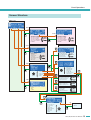
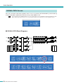
Screen Structure
METER
SETTING
• ANA INPUT VOLTAGE
• SLOT INPUT VOLTAGE
• SP OUTPUT VOLTAGE
• SP OUTPUT POWER
• SP OUTPUT IMPEDANCE
• SLOT OUTPUT METER
• THERMAL
UTILITY
• Device Setup
• Word Clock Setup
• Information
• Network Setup
• LCD Setup
• Front Panel Operation
• Scene Setup
• Misc Setup
SCENE
• RECALL
• STORE
• EDIT
• CLEAR
MENU
• General
• Signal Path
• Signal Chain
• Calibration
• Limiter
• Sensitivity/Amp Gain
• Stereo/Bridge/Parallel
• Attenuation Link
• Input Redundancy
• Analog Input Signal Chain
• Slot Input Signal Chain
• Output Signal Chain
• Input Router
• Input On/Off
• 4x4 Matrix Mixer
• 8Band Input EQ
• Input Delay
• Oscillator Mix
• Speaker Processor
• Output Router
• ANA INPUT VOLTAGE
• SLOT INPUT VOLTAGE
• SP OUTPUT VOLTAGE
• SP OUTPUT POWER
• SP OUTPUT IMPEDANCE
• SLOT OUTPUT METER
• THERMAL
• X-Over Input Level
• X-Over Polarity
• X-Over
• Output Delay
• 6Band Output EQ
• Output Level
• Mute On/Off
• Limiter
• RECALL
LIB.
• Calibrate by Pilot Tone
• Calibrate by Prog Source
• Voltage Limiter
• Power Limiter
• Limiter Gain Reduction
HOME Screen
METER Screen
UTILITY Screen
MENU Screen
SCENE Screen
SETTING Screen
General
Signal Path
Signal Chain
Calibration
Limiter
Speaker Processor
Library
Encoder
Encoder
Encoder

TX6n/5n/4n Reference Manual
14
Panel Operations
*Scene..........The settings listed above, such as Standby/Power-On or mute (with the exception of UTILITY), are called a “scene”. By recalling a scene, the
saved settings can be immediately applied to the amplifiers.
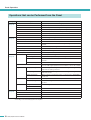
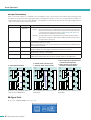
Operations that can be Performed from the Panel
Category Subcategory Explanation
METER
(page 16)
ANA INPUT VOLTAGE Shows the input level from the analog input connectors.
SLOT INPUT VOLTAGE Shows the input level from the slot.
SP OUTPUT VOLTAGE Shows the output level from the [SPEAKERS] connectors.
SP OUTPUT POWER Shows the output power from the [SPEAKERS] connectors.
SP OUTPUT IMPEDANCE Shows the output impedance from the [SPEAKERS] connectors.
SLOT OUTPUT METER Shows the output level to the slot.
THERMAL Shows the heat sink temperature.
UTILITY
(page 19)
Device Setup Makes settings to distinguish the amplifier on a network.
Word Clock Setup Sets the word clock.
Information Shows information about the amplifier.
Network Setup Specifies the IP address and other settings for using the amplifier in a
network.
LCD Setup Specifies the display settings.
Front Panel Operation Turns panel operation lock on/off.
Scene Setup Makes scene* settings.
Misc Setup Sets the amplifier’s internal clock, etc.
MENU
(page 24)
General Sensitivity/Amp Gain Sets the input sensitivity/gain.
Stereo/Bridge/Parallel Specifies the amplifier’s mode (Stereo/Bridge/Parallel).
Attenuation Link Specifies whether attenuator operation will be linked between channels
A and B.
Input Redundancy Specifies the redundant connection mode, etc.
Signal Path Makes settings for the equalizer, delay, crossover, and others that pro-
cess the audio signal. Speaker Processor libraries can also be recalled.
Signal Chain Analog Input Signal Chain Makes settings for checking whether the audio signal is being correctly
input from the analog connectors.
Slot Input Signal Chain Makes settings for checking whether the audio signal is being correctly
input from the slot.
Output Signal Chain Makes settings for checking the status of output from the [SPEAKERS]
connectors.
Calibration Calibrate by Pilot Tone Uses a pilot tone to measure the impedance of the connected speakers.
Calibrate by Prog Source Uses an audio signal to measure the impedance of the connected
speakers.
Limiter Voltage Limiter Makes settings for the limiter.
Power Limiter
Limiter Gain Reduction Specifies whether the limiter will be linked between channels A and B.
SCENE
(page 40)
Recall Recalls a scene*.
Store Stores a scene*.
Edit Edits a scene*.
Clear Clears a scene*.

TX6n/5n/4n Reference Manual
15
Panel Operations
When an alert event occurs related to the amplifier’s audio, such as when an abnormality has occurred in the
amplifier, an alert message will appear in the upper part of the display. At this time the [ALERT] indicator of each
channel will also light.
If Amp Editor is being used online, the alert message will also appear in Amp Editor.
When an alert event occurs, it will be recorded in the event log of the amplifier itself, and the recorded event log can be viewed
in Amp Editor’s “Event Log” dialog box.
In Amp Editor’s “Alert Setup” dialog box you can enable/disable alert events and select their types. If an alert type is set to
Information, the alert message will not appear in the display.
For details on the content of each alert and the appropriate measures to take, refer to the Amp Editor Owner’s Manual.
For details about the alert messages appearing when certain malfunctions are suspected to have occurred, you can also refer to
“Alert Message List (Excerpt)” (page 56).
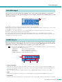
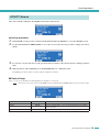
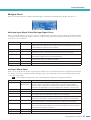
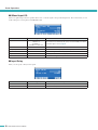
This shows information such as the currently selected scene name and attenuation. This screen will appear imme-
diately after you power-on the amplifier. You can also access it by pressing the [HOME] button, or by pressing the
[EXIT] button several times. You can also move from this screen to various other screens.
• As a shortcut from the HOME screen, you can hold down one of the following buttons for three (or one) seconds or longer
to execute the corresponding function (page 7).
[HOME] button : Switch power between Standby/On
[EXIT] button : Reset the FAULT OUTPUT connector
[ENTER] button : Access the UTILITY screen Device Setup
[HOME] + [EXIT] button : Temporarily defeats panel lock
q Scene information
This shows the number and name of the currently recalled scene. The scene name can be specified in the SCENE screen
(page 42) or in Amp Editor. Instead of the scene name, you can choose to display the library name for the Speaker Proces-
sor component (page 24).
When you edit a parameter after recalling or storing a scene, an EDIT symbol will appear above the scene number.
w Gain
This indicates the currently specified gain for each channel. The gain can be adjusted in the MENU screen (page 24).
e Attenuation
This indicates the current attenuation for each channel. You can use encoders A/B to adjust the attenuation for each channel.
Alert Messages
HOME Screen
Alert message
NOTE
w
q
we

TX6n/5n/4n Reference Manual
16
Panel Operations
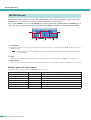
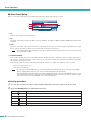
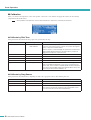
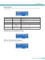
This shows the input/output levels of the audio signal, and the status of the power supply. As when you’re in the
HOME screen, you can use encoders A/B to adjust the attenuation of each channel.
To access the METER screen, access the HOME screen and press the left-most function button (METER). You can
change the meter type by using the left-most function button (PREV) and right-most function button (NEXT).
q Level meter
This shows the name of the currently selected meter type and the meter for each channel. The “<” “>” beside the meter are
threshold values.
• When the input level from an analog input jack or slot exceeds the maximum value of digital signal, the top segment of
the meter will light.
w Gain
This indicates the currently specified gain for each channel. The gain can be adjusted in the MENU screen (page 24).
e Attenuation
This indicates the current attenuation for each channel. You can use encoders A/B to adjust the attenuation for each channel.
● Meter types that can be shown
The display units can be specified in the SETTING screen (page 17).
METER Screen
Meter type Display unit Explanation
ANA INPUT VOLTAGE dBFS, dBu, V Input level from the analog jack
SLOT INPUT VOLTAGE dBFS Input level from the slot
SP OUTPUT VOLTAGE dBu, V Speaker output level
SP OUTPUT POWER W Speaker output power
SP OUTPUT IMPEDANCE Ω Speaker output impedance
SLOT OUTPUT METER dBFS Slot output level
THERMAL % Heat sink temperature of amplifier section
e
ww
eq
NOTE

TX6n/5n/4n Reference Manual
17
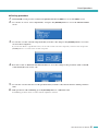
Panel Operations
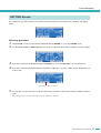
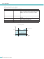
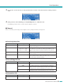
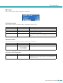
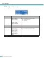
For each meter type, this screen lets you specify various parameters for alert detection, peak hold, and display
units.
● Setting procedure
1. In the HOME screen, press the left-most function button (METER) to access the METER screen.
2. Use the function buttons (PREV/NEXT) to access the screen for the meter whose settings you want to change.
3. Press the second-from-right function button (SETTING) to access the SETTING screen for that meter.
4. Press the second-from-left function button (CH A/B or CH 1/2) to access the settings for the channel that you
want to edit.
5. Use encoder A to move the cursor to the parameter that you want to edit, and encoder B to edit the parameter
value.
The edited parameter value will be reflected by the amplifier in real time.
SETTING Screen
Channel whose settings you will edit

TX6n/5n/4n Reference Manual
18
Panel Operations
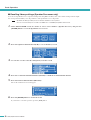
● Parameters that can be edited
The parameters that can be edited will depend on the meter type.
* The setting range will differ depending on the meter type.
Parameter Range Explanation
Detect Enable ON/OFF Specifies whether alert detection will be enabled or disabled. An alert
message will be displayed if a point exceeding the specified value (Alert
Min/Max TH) is detected for the specified number of times (Detect
Count) within the specified duration (Detect Time). Detection is in 2 ms
intervals.
Alert Min TH * Specifies the lower threshold value for the alert.
Alert Max TH * Specifies the upper threshold value for the alert.
Detect Time 1–10s Specifies the time during which points exceeding the threshold value will
be counted.
Detect Count 1–100 Specifies the number of times that a point exceeding the threshold value
must be counted in order to trigger an alert.
Peak Hold ON/OFF Turns peak hold on/off.
Unit * Specifies the display unit for the meter.
now
Time
Value
Max TH
Min TH
= Detect Count
Detect Time
Alert detection parameters

TX6n/5n/4n Reference Manual
19
Panel Operations
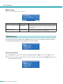
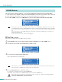
Here you can make settings for the amplifier itself and for the network.
● Setting procedure
1. In the HOME screen, press the second-from-left function button (UTILITY) to access the UTILITY screen.
2. Use the function buttons (PREV/NEXT) to access the screen for the sub-category whose settings you want to
change.
3. Use encoder A to move the cursor to the parameter that you want to edit, and encoder B to edit the parameter
value.
4. If the parameter value is blinking, press the [ENTER] button to confirm the value.
Non-blinking parameter values are reflected by the amplifier in real time.
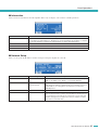
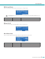
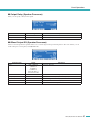
■ Device Setup
Here you can specify identifiers for distinguishing the amplifier on a network.
•You can also access this screen from the HOME screen by holding down the [ENTER] button for three seconds or longer.
UTILITY Screen
Parameter name Range Explanation
Device ID 0–255 This is an ID for uniquely identifying the device within a network.
Identify ON/OFF Lights the [Identify] button of the corresponding amplifier in Amp Editor’s
Tree View window.
Label — Displays the label (name) of this amplifier as assigned by Amp Editor.
NOTE

TX6n/5n/4n Reference Manual
20
Panel Operations
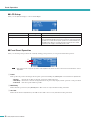
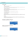
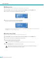
■ Word Clock Setup
Here you can select the master word clock that will synchronize digital audio signal processing.
q Fs
Indicates the current word clock frequency.
w Int
The status of the internal word clock. There are four possibilities: 44.1 kHz / 48 kHz / 88.2 kHz / 96 kHz. The default setting
is 96 kHz.
e Slot
The word clock status of the card inserted in the slot. Normally, the reference word clock signal is transmitted from a single
device, and the other devices will receive and synchronize to this word clock signal.
• If a card with a built-in SRC (sampling rate converter) is installed, select the master word clock from other than the chan-
nels with the SRC enabled.
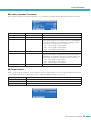
r Auto Scan Mode
This specifies whether the master clock will be switched automatically when a valid word clock is no longer being input to
the port that’s assigned as the master clock, or when a port of the slot is found to have a valid word clock being input while
the internal word clock is selected.
If this setting is ON, the master clock will automatically be switched according to the following order of priority.
1. The selected port of the slot
2. The internal word clock
•For some types of installed I/O card (e.g., for an AD card), Auto Scan Mode will not operate even if this setting is ON.
Refer to “Supported I/O cards” (page 9) to check if your I/O card supports Auto Scan Mode.
• If two TXn amplifiers are bi-directionally connected via a digital I/O card (e.g., separately sold AES/EBU cards connected
via the D-sub 25 pin connectors), and if Auto Scan Mode is ON for both units, the word clock will loop, and will no longer
lock. In this case, turn Auto Scan Mode OFF for one of the TXn amplifiers.
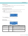
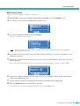
● Setting procedure
1. Use encoder A to move the cursor to the port (Int or Slot) that you want to assign as the master clock.
2. Press the [ENTER] button to switch the master clock.
A word clock is being input, and can be selected as the master clock.
A valid word clock is not being input (and cannot be selected as the master clock).
A word clock is being input, but is not synchronized with the master clock.
Selected as the master clock.
Selected as the master clock, but a valid clock is not being input.
An invalid channel of the slot, an analog I/O card is installed, or no card is installed.
q
w
r
e
NOTE
NOTE
Strona się ładuje...
Strona się ładuje...
Strona się ładuje...
Strona się ładuje...
Strona się ładuje...
Strona się ładuje...
Strona się ładuje...
Strona się ładuje...
Strona się ładuje...
Strona się ładuje...
Strona się ładuje...
Strona się ładuje...
Strona się ładuje...
Strona się ładuje...
Strona się ładuje...
Strona się ładuje...
Strona się ładuje...
Strona się ładuje...
Strona się ładuje...
Strona się ładuje...
Strona się ładuje...
Strona się ładuje...
Strona się ładuje...
Strona się ładuje...
Strona się ładuje...
Strona się ładuje...
Strona się ładuje...
Strona się ładuje...
Strona się ładuje...
Strona się ładuje...
Strona się ładuje...
Strona się ładuje...
Strona się ładuje...
Strona się ładuje...
Strona się ładuje...
Strona się ładuje...
Strona się ładuje...
Strona się ładuje...
Strona się ładuje...
Strona się ładuje...
-
 1
1
-
 2
2
-
 3
3
-
 4
4
-
 5
5
-
 6
6
-
 7
7
-
 8
8
-
 9
9
-
 10
10
-
 11
11
-
 12
12
-
 13
13
-
 14
14
-
 15
15
-
 16
16
-
 17
17
-
 18
18
-
 19
19
-
 20
20
-
 21
21
-
 22
22
-
 23
23
-
 24
24
-
 25
25
-
 26
26
-
 27
27
-
 28
28
-
 29
29
-
 30
30
-
 31
31
-
 32
32
-
 33
33
-
 34
34
-
 35
35
-
 36
36
-
 37
37
-
 38
38
-
 39
39
-
 40
40
-
 41
41
-
 42
42
-
 43
43
-
 44
44
-
 45
45
-
 46
46
-
 47
47
-
 48
48
-
 49
49
-
 50
50
-
 51
51
-
 52
52
-
 53
53
-
 54
54
-
 55
55
-
 56
56
-
 57
57
-
 58
58
-
 59
59
-
 60
60


Yamaha TX4n Instrukcja obsługi
- Kategoria
- Sprzęt muzyczny
- Typ
- Instrukcja obsługi
- Niniejsza instrukcja jest również odpowiednia dla
w innych językach
- čeština: Yamaha TX4n Uživatelský manuál
- español: Yamaha TX4n Manual de usuario
- italiano: Yamaha TX4n Manuale utente
- Deutsch: Yamaha TX4n Benutzerhandbuch
- svenska: Yamaha TX4n Användarmanual
- português: Yamaha TX4n Manual do usuário
- français: Yamaha TX4n Manuel utilisateur
- Türkçe: Yamaha TX4n Kullanım kılavuzu
- English: Yamaha TX4n User manual
- dansk: Yamaha TX4n Brugermanual
- русский: Yamaha TX4n Руководство пользователя
- suomi: Yamaha TX4n Ohjekirja
- Nederlands: Yamaha TX4n Handleiding
- română: Yamaha TX4n Manual de utilizare
Powiązane artykuły
-
Yamaha TX6n Instrukcja obsługi
-
Yamaha V1 Instrukcja obsługi
-
-
-
-
-
-
-
-