
LED SOLAR SPOTLIGHT
Assembly, operating and safety instructions
NAPELEMES LED REFLEKTOR
Szerelési, használati és biztonsági tudnivalók
LED SOLÁRNÍ REFLEKTOR
Pokyny k montáži, obsluze a bezpečnostní pokyny.
LED-SOLAR-STRAHLER
Montage-, Bedienungs- und Sicherheitshinweise
REFLEKTOR SOLARNY LED
Wskazówki montażu, obsługi i bezpieczeństwa
LED SOLARNI REFLEKTOR
Navodila za montažo, uporabo in varnostna navodila
LED SOLÁRNY REFLEKTOR
Pokyny pre montáž, obsluhu a bezpečnostné pokyny
4
Z31171

GB Assembly, operating and safety instructions Page 3
PL Wskazówki montażu, obsługi i bezpieczeństwa Strona 10
HU Szerelési, használati és biztonsági tudnivalók Oldal 17
SI Navodila za montažo, uporabo in varnostna navodila Stran 24
CZ Pokyny k montáži, obsluze a bezpečnostní pokyny. Strana 31
SK Pokyny pre montáž, obsluhu a bezpečnostné pokyny Strana 38
DE / AT / CH Montage-, Bedienungs- und Sicherheitshinweise Seite 45

3 GB
Intended use ................................................................................................................................. Page 4
Description of Parts ................................................................................................................Page 4
Included items .............................................................................................................................Page 4
Technical data ..............................................................................................................................Page 4
Safety notes ..................................................................................................................................Page 4
Safety instructions for rechargeable batteries ................................................................................... Page 5
Functioning .....................................................................................................................................Page 5
Charging the rechargeable battery ..........................................................................Page 5
Assembly
Mounting the spotlight ........................................................................................................................ Page 6
Mounting the solar cell .......................................................................................................................Page 6
Preparing the product for use
Switching the motion detector on and off .........................................................................................Page 7
Setting the lighting duration ................................................................................................................Page 7
Adjusting the sensitivity of the sensor ................................................................................................. Page 7
Setting the daylight level ....................................................................................................................Page 7
Orientating the motion detector .........................................................................................................Page 7
Maintaining the device
Replacing the rechargeable battery ..................................................................................................Page 7
Cleaning and storage ...........................................................................................................Page 8
Troubleshooting ........................................................................................................................Page 8
Disposal ............................................................................................................................................Page 9

4 GB
LED solar spotlight
Intended use
The solar spotlight is used to provide illumination in
outdoor and indoor areas where no power connec-
tion is available (e.g. garden houses, garages etc.).
This product is not intended for commercial use.
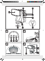
Description of Parts
1 Low voltage socket
2 Mounting hole for main station
3 Main station
4 AUTO / OFF switch
5 Locking screw (motion detector)
6 Motion detector
7 Spotlight
8 Rotary control LUX (light sensitivity)
9 Rotary control SENS (sensitivity)
10 Rotary control TIME (switched on duration)
11 Solar electricity socket
12 Screw (ø 4.5 x 43 mm)
13 Solar cell
14 Screw (ø 3.7 x 28 mm)
15 Solar cable plug
16 Mounting holes for solar cell
17 Wall bracket
18 Dowel (ø 8 mm)
19 Signal LED
20 Lead gel rechargeable battery
Included items
Immediately after unpacking, check that all the
items and accessories are present and that the
device is in perfect condition.
1 Main station (consists of spotlight with 80LEDs,
motion detector, battery housing with built-in
rechargeable battery)
1 Solar cell (incl. approx. 4.8 m power cable)
2 Screws (mounting material for main station,
ø 4.5 x 40 mm)
4 Screws (mounting material for solar cell,
ø 3.7 x 28 mm)
2 Dowel (mounting material for main station,
ø 8 mm)
4 Dowel (mounting material for solar cell, ø 6 mm)
1 Operating instructions
Technical data
Operating voltage: 12 V
Lead gel rechargeable
battery: 6 V , 4Ah, dimensions:
10 x 7 x 4.5 cm
Lamp: 80LEDs, 0.06 W
Solar cell: 150 x 200 mm,
amorphous, 2 Wp,
max. 10 V , 140 mA
Connection for
charging device: 12 V , min. 400 mA,
polarity , DC con-
nector 5.5 x 2.1 mm
(charging device not
included with delivery.)
Dimming switch: Adjustable from approx.
10 lx–20,000 lx
Motion detector:
Range: Max. 12 m
Detection angle: approx. 180° horizontal,
50 ° vertical
Protection type: IP44 (splash-proof)
Safety notes
DANGER TO
LIFE AND ACCIDENT HAZARD
FOR TODDLERS AND SMALL
CHILDREN! Never leave children unsupervised
with the packaging materials. The packaging
material presents a danger of suffocation.
Children often underestimate dangers. Always
keep children away from the product.
DANGER TO LIFE! During installation keep
children away from the area in which you are

5 GB
working. A large number of screws and other
small parts are included with delivery. These may
prove life-threatening if swallowed or inhaled.
Children or other individuals who do not know
or have no experience of handling this device,
or whose physical, sensory or mental abilities
are restricted, must not use the device without
supervision or instruction by an individual respon-
sible for their safety. Children must never be
allowed to play with the device.
Do not use the article if you detect any kind of
damage.
Safety instructions for
rechargeable batteries
Fire hazard! Do not allow recharge-
able batteries to short-circuit. Other-
wise the rechargeable batteries may
overheat, become a fire hazard or explode.
EXPLOSION HAZARD! Never
throw rechargeable batteries into
fire or water. Outdated or used
rechargeable batteries may leak chemical fluids
that damage the product. Therefore, remove
the rechargeable battery when the spotlight is
not required longer periods of time.
WEAR PROTECTIVE GLOVES! If
they come into contact with skin,
leaked or damaged rechargeable
batteries could cause chemical burns; you
should therefore wear suitable protective
gloves at all times if such an event occurs.
Only use rechargeable batteries of the right
size and of the recommended type (see section
”Technical data”).
Functioning
When exposed to sunlight, the solar cell 13 converts
the light into electrical energy and via the connected
solar electricity socket 11 , stores the electricity in
the built-in rechargeable battery 20 . With a fully
charged rechargeable battery, the lighting duration
is about 2 hours. Before being used for the first
time, the rechargeable battery must be fully loaded
(see section “Charging the rechargeable battery”).
Charging the
rechargeable battery
Upon delivery, the rechargeable battery 20 is fully
charged. Due to storage times, the rechargeable
battery may be partially discharged when first
used. Therefore, charge the rechargeable battery
completely before first use. You may select between
2 available options for charging:
Charging the rechargeable battery
with a charging device (external power
supply unit)
Slide the AUTO / OFF switch 4 into the OFF
position.
Insert the plug of the charging device (not included
with delivery) into the low voltage socket 1 of
the main station. The technical data of the
charging device must comply with information
given in the section “Technical data”.
Note: During the charging process, the solar
cell 13 must not be connected with the main
station 3.
Note: The signal LED 19 next to the charging
socket lights red for as long as the charging is
in process. The signal LED lights green as soon
as the charging process has ended. The recharge-
able battery is now ready for use.
Note: Depending on the charge state of the
battery, the charging process may take up to
24hours. The built-in charging controller of the
spotlight prevents the rechargeable battery
from overload.
Charging the rechargeable batteries with
a solar cell
Slide the AUTO / OFF switch into the OFF posi-
tion, so the charging process is not influenced
by the light being switched on.
Insert the plug 15 of the solar cell cable into
the solar electricity socket 11 of the spotlight.
Position the solar cell as described in section
“Mounting the solar cell”.

6 GB
Note: With steady exposure to sunlight, the
rechargeable battery is fully charged after 4 to
6 days. The duration of the charging process
depends on the charge state of the rechargea-
ble battery as well as the quality of the expo-
sure to sunlight.
Assembly
Before mounting, decide where you want to
mount the solar cell 13 and the main station 3.
The soar cell and the main station can be
mounted independently of each other, but after
being mounted must be connected with the ap-
prox. 4.8 m long power cable of the solar cell.
After the mounting, lay the cable so it is not
subject to any mechanical stresses. Use typical
installation material such as cable clamps or
conduit to fasten the cable, to prevent damage
to the insulation.
Note: The included mounting material is suita-
ble for ordinary solid concrete or masonry
construction. Other wall substrates may require
other fastening materials. Seek specialist
advice if necessary.
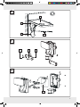
Mounting the spotlight
When selecting the mounting location for the main
device, pay attention to the following:
– Make sure the spotlight 7 of the main station 3
illuminates the desired area. You can move the
spotlight.
– Make sure the motion detector 6 covers the
desired area. The motion detector has a maxi-
mum coverage range of 12 m, with a coverage
angle of about 180° (depending on the
mounting height – a height of 2.00 m–2.50 m
is ideal) (see Fig. B and C).
– Make sure the motion detector is not illuminated
at night by street lighting. This can influence its
functioning.
Note: You can mount the main station with the
mounting holes 2 or the included wall bracket 17 .
Mounting with the mounting holes:
Drill 2 holes. Mount the main station with the
mounting holes by using the dowel 18
(ø 8 mm) and screws 12 (ø 4.5 x 43 mm)
(see Fig. D).
After mounting, check that the main station is
fitted securely.
Mounting with the wall bracket:
Drill 2 holes. Mount the wall bracket 17 by
using the dowel (ø 8 mm) and screws
(ø 4.5 x 43 mm) (see Fig. F).
Note: The included mounting material is suitable
for ordinary solid concrete or masonry construc-
tion. Other wall substrates may require other
fastening materials. Seek specialist advice if
necessary.
After mounting, check that the wall bracket is
fitted securely.
Install the main station onto the wall bracket
(see Fig. F).
Check that the main station is fitted securely.
Mounting the solar cell
When selecting the mounting location for the solar
cell 13 , pay attention to the following:
– The solar cell needs to be as directly exposed
to sunlight as possible. Even partial shading of
the solar cell during the day can have a signifi-
cant influence on charging.
Cardinal direction:
Orientation towards the south is optimum. Orienta-
tions with slight deviations towards the west are
preferable to those with slight deviations towards
the east.
Horizontal orientation:
The horizontal orientation of the solar cell depends
on the geographic latitude of the mounting location.
In central Europe, and angle of 30°–40° is ideal.
Drill 4 holes. Mount the solar cell by using
the dowel 18 (ø 8 mm) and screws 14

7 GB
(ø 3.7 x 28 mm). To do so, use the pre-finished
mounting holes (see Fig. E).
After mounting, check that the solar cell is fitted
securely.
Note: After mounting, orient the solar cell by
tilting it. The solar cell is fitted with a joint which
locks every 18° to permit orientation.
Preparing the product for use
Switching the motion detector
on and off
Slide the AUTO / OFF switch 4 into the AUTO
position to switch on the motion detector 6.
Slide the AUTO / OFF switch into the OFF posi-
tion to switch off the motion detector.
Setting the lighting duration
Turn the rotary control TIME 10 on the bottom
of the motion detector 6 clockwise to increase
the duration of the illumination. The lighting
duration can be adjusted within a time window
of approx. 10–60seconds.
Adjusting the sensitivity of
the sensor
Turn the rotary control SENS 9 on the bottom
of the motion detector 6 clockwise to in-
crease the sensitivity of the sensor.
Note: The motion detector responds to heat
radiation. When outdoor temperatures are low,
it is more sensitive to body heat than when out-
door temperatures are warm. Be sure to regu-
late the sensitivity of the sensor over the course
of the year.
Setting the daylight level
Turn the rotary control LUX 8 on the bottom of
the motion detector 6 clockwise to increase
the daylight level. In position , the motion
detector only responds at pitch-black night
(approx. 50 lx). In position , the motion
detector also responds at daylight levels, as
long as about 20,000lx are not exceeded.
Orientating the motion
detector
Loosen the fastening screws 5 of the motion
detector 6.
Turn the rotary control LUX 8 to position .
Orient the motion detector into the central
region of the desired coverage area.
Move about through the coverage area until
you are satisfied with the response characteris-
tics of the motion detector. To find the proper
orientation, change the position of the rotary
control SENS 9 or the orientation of the
motion detector.
Re-tighten the fastening screws to fix the adjust-
ment.
Turn the rotary control LUX to the desired posi-
tion. These can be determined during the dawn
or twilight hours during which the spotlight 7
should respond. Slowly turn the rotary control
LUX clockwise until it reacts to movement within
the coverage area.
Maintaining the device
Replacing the
rechargeable battery
Note: This work step requires a Phillips screwdriver
and a flat-nose pliers.
Note: Suitable batteries that comply with the
specifications listed under “Technical data” are
available in specialist shops.
Replace the battery 20 if after a certain
amount of time, the light duration diminishes
noticeably despite good exposure to sunlight.
Only use rechargeable batteries of the right

8 GB
size and of the recommended type (see section
“Technical data”).
Replace the rechargeable battery as indicated
in Figure G.
Slide the AUTO / OFF switch 4 into the OFF
position.
Use the screwdriver to remove the screws from
the back side of the main station 3. Remove
the front of the main station.
Use the screwdriver to remove the 4screws of
the 2fastening brackets and remove the fasten-
ing brackets.
Note: The clamps for the rechargeable batter-
ies are fitted with plug connectors. The brown
cable is connected to the positive terminal of
the rechargeable battery (marked in red on the
battery) and the black cable to the minus termi-
nal (marked in black on the battery).
Use the flat-nosed pliers to pull out the plug
connector. When so doing, pull on the plug
connectors and not on the cable.
Reinsert the new battery in the same way you
have removed the old.
Use the screws to re-fasten the fastening brack-
ets and the front of the main station.
Cleaning and storage
Slide the AUTO / OFF switch 4 into the OFF
position if you will not be using the spotlight
and want to store it.
Charge the rechargeable batteries 20 every
3months to prevent their destruction due to
deep discharge (see section “Charging the
rechargeable batteries”). Lead gel rechargeable
batteries have a high self-discharge rate.
Check the motion detector 6 and the solar
cell 13 for dirt regularly. If dirt or is present,
remove it to guarantee flawless function of the
spotlight.
Especially during the winter, keep the device
free from snow and ice.
Clean the spotlight with a lint-free, slightly moist
cloth and mild cleaning agent.
Troubleshooting
= Fault
= Cause
= Solution
= The spotlight does not switch on.
= The AUTO / OFF switch 4 is in the OFF position.
= Slide the AUTO / OFF switch into the AUTO
position.
= The rotary control LUX 8 is adjusted too dark.
= Adjust the LUX control so it is brighter.
= The motion detector 6 is dirty or is incorrectly
oriented.
= Clean the motion detector or reorient it.
= The sensitivity of the motion detector is too low.
= Readjust the sensitivity of the motion detector (see
section “Adjusting the sensitivity of the sensor”).
= The rechargeable battery 20 is discharged.
= Charge the rechargeable battery (see section
“Charging the rechargeable battery”).
= The spotlight also switches on when it
is light out.
= The LUX control is adjusted too bright.
= Adjust the LUX control so it is darker.
= The spotlight flickers.
= The rechargeable battery is almost discharged.
= Charge the rechargeable battery (see section
“Charging the rechargeable battery”).
= The rechargeable battery loses its
charge after a short time.
= The plug connection of the solar cell 13 and
main station 3 has come loose.
= Refasten the plug connection at the device.
= The solar cell is dirty.
= Clean the solar cell.
= The solar cell is unfavourably oriented.
= Re-align the solar cell (see section “Mounting
the solar cell”).
= The rechargeable battery can no
longer be charged, even from a
power supply unit.
= The rechargeable battery is defective.

9 GB
= Replace the rechargeable battery (see section
“Replacing the rechargeable battery”).
Disposal
The packaging is made entirely of recy-
clable materials which you can dispose
of at your local recycling facilities.
Contact your local community or municipal admin-
istration for more details on how to dispose your
worn-out product.
To help protect the environment, please
properly dispose of the product when it
has reached the end of its useful life, not
through household waste. Contact your
municipal authorities for information
regarding collection points and their
opening hours.
Faulty or used rechargeable batteries must be recy-
cled in accordance with Directive 2006 / 66 / EC.
Return rechargeable batteries and / or the appli-
ance using the recycling facilities provided.
Pb
Environmental damage
through incorrect disposal of
the rechargeable batteries!
Rechargeable batteries may not be disposed of
with the usual domestic waste. They may contain
toxic heavy metals and are subject to hazardous
waste regulations. The chemical symbols of the
heavy metals are: Cd = cadmium, Hg = mercury,
Pb = lead.
EMC

10 PL
Przeznaczenie .......................................................................................................................... Strona 11
Opis części ................................................................................................................................... Strona 11
Zawartość zestawu .............................................................................................................Strona 11
Dane techniczne......................................................................................................................Strona 11
Wskazówki dotyczące bezpieczeństwa ........................................................... Strona 11
Wskazówki dotyczące bezpiecznego używania akumulatorów .................................................Strona 12
Sposób działania ..................................................................................................................Strona 12
Ładowanie akumulatora ...............................................................................................Strona 12
Montaż
Montaż reflektora ............................................................................................................................Strona 13
Montaż ogniwa solarnego ..............................................................................................................Strona 13
Uruchomienie
Włączanie / wyłączania czujnika ruchu ........................................................................................Strona 14
Ustawianie czasu świecenia: ..........................................................................................................Strona 14
Ustawienie czułości czujnika ...........................................................................................................Strona 14
Ustawianie poziomu światła dziennego ........................................................................................Strona 14
Ustawianie czujnika ruchu ...............................................................................................................Strona 14
Konserwacja urządzenia
Wymiana akumulatora ....................................................................................................................Strona 15
Czyszczenie iprzechowywanie ................................................................................Strona 15
Usuwanie usterek .................................................................................................................Strona 15
Utylizacja .....................................................................................................................................Strona 16

11 PL
Reflektor solarny LED
Przeznaczenie
Lampa solarna służy do oświetlania zarówno na
zewnątrz, jak iwzamkniętych pomieszczeniach,
wktórych dostępne jest przyłącze sieci elektrycznej
(np. altanki ogrodowe, garaże itp.). Produkt nie jest
przeznaczony do użytku komercyjnego.
Opis części
1 Gniazdo niskiego napięcia
2 Otwór mocujący dla stacji głównej
3 Stacja główna
4 Przełącznik AUTO / OFF
5 Śruba ustalająca (czujnik ruchu)
6 Czujnik ruchu
7 Reflektor
8 Pokrętło regulacyjne LUX (światłoczułość)
9 Pokrętło regulacyjne SENS (czułość)
10 Pokrętło regulacyjne TIME (czas włączenia)
11 Gniazdo prądu solarnego
12 Śruba (ø4,5 x 43 mm)
13 Ogniwo solarne
14 Śruba (ø3,7 x 28 mm)
15 Wtyczka kabla solarnego
16 Otwory mocujące dla ogniwa solarnego
17 Uchwyt ścienny
18 Kołek (ø8 mm)
19 Dioda sygnalizacyjna
20 Akumulator ołowiowo-żelowy
Zawartość zestawu
Bezpośrednio po wypakowaniu należy sprawdzić,
czy zestaw jest kompletny oraz czy urządzenie
znajduje się wnienagannym stanie.
1 stacja główna (składająca się z80 diod LED,
czujnika ruchu iobudowy akumulatora zwbu-
dowanym akumulatorem)
1 ogniwo solarne (zkablem prądowym odługości
ok. 4,8 m)
2 śruby (materiał montażowy do stacji głównej,
ø4,5 x 40 mm)
4 śruby (materiał montażowy do ogniwa solarnego,
ø3,7 x 28 mm)
2 Kołki (materiał montażowy do stacji głównej,
ø8 mm)
4 kołki (materiał montażowy do ogniwa solarnego,
ø6 mm)
1 instrukcja obsługi
Dane techniczne
Napięcie robocze: 12 V
Akumulator
ołowiowo-żelowy: 6 V , 4Ah,
wymiary: 10 x 7 x 4,5 cm
Źródło światła: 80 diod LED, 0,06 W
Ogniwo solarne: 150 x 200 mm, amorficzne,
2 Wp, maks. 10 V , 140 mA
Przyłącze ładowarki: 12 V , min. 400 mA,
biegunowość ,
wtyczka DC 5,5 x 2,1 mm
(Ładowarka nie jest dołą-
czona do zestawu.)
Przełącznik
zmierzchowy: regulowany
ok. 10lx–20000lx
Czujnik ruchu:
Zasięg: maks. 12 m
Kąt wykrywalności: ok. 180° poziomo,
50 ° pionowo
Stopień ochrony: IP44 (zabezpieczenie przed
wodą bryzgową)
Wskazówki dotyczące
bezpieczeństwa
NIEBEZPIE-
CZEŃSTWO UTRATY ŻYCIA
LUB ODNIESIENIA OBRAŻEŃ
PRZEZ DZIECI! Nigdy nie należy pozosta-
wiać dzieci zmateriałem opakowaniowym bez
nadzoru. Istnieje niebezpieczeństwo uduszenia

12 PL
się materiałem opakowaniowym. Dzieci często
nie uświadamiają sobie niebezpieczeństwa.
Dzieci nie powinny mieć dostępu do produktu.
ZAGROŻENIE ŻYCIA! Podczas montażu
należy pilnować, aby wpobliżu miejsca pracy
nie było dzieci. Wzestawie znajduje się wiele
śrub iinnych małych elementów. Wrazie ich
połknięcia lub przedostania się do dróg odde-
chowych mogą stanowić zagrożenie dla życia.
Niedozwolone jest używanie urządzenia
przez osoby nieposiadające odpowiedniej
wiedzy idoświadczenia, przez dzieci iosoby
oograniczonej sprawności fizycznej, senso-
rycznej bądź umysłowej, chyba że odbywać
się to będzie pod nadzorem osoby odpowie-
dzialnej za ich bezpieczeństwo. Należy dopil-
nować, aby dzieci nie bawiły się urządzeniem.
Nie używać urządzenia wrazie stwierdzenia
jakichkolwiek uszkodzeń.
Wskazówki dotyczące
bezpiecznego używania
akumulatorów
ZAGROŻENIE POŻAROWE!
Nie należy zwierać biegunów aku-
mulatorów. Może to spowodować
przegrzanie, zagrożenie pożarowe lub pęknię-
cie akumulatorów.
NIEBEZPIECZEŃSTWO WYBU-
CHU! Nigdy nie należy wrzucać
akumulatorów do ognia lub wody.
Zprzestarzałych lub zużytych akumulatorów
mogą wypłynąć chemiczne płyny, które uszko-
dzą produkt. Dlatego należy wyjąć akumula-
tory zlampy, jeżeli nie będzie używana przez
dłuższy czas.
NOSIĆ RĘKAWICE OCHRONNE!
Akumulatory, zktórych nastąpił
wyciek, lub akumulatory uszkodzone
mogą wprzypadku kontaktu ze skórą spowo-
dować oparzenie substancją żrącą; dlatego
wtakim przypadku należy koniecznie stosować
odpowiednie rękawice ochronne.
Należy używać wyłącznie akumulatorów
właściwej wielkości izalecanego typu (patrz
rozdział „Dane techniczne”).
Sposób działania
Przy nasłonecznieniu ogniwo solarne 13 przetwa-
rza światło wenergię słoneczną imagazynuje ją
przez podłączone gniazdo prądu solarnego 11
we wbudowanym akumulatorze 20 . Przy całkowi-
cie naładowanym akumulatorze czas oświetlenia
wynosi ok. 2godzin. Przed pierwszym uruchomie-
niem akumulator musi być naładowany (zobacz
rozdział „Ładowanie akumulatora”).
Ładowanie akumulatora
Akumulator 20 wchwili dostawy jest całkowicie
naładowany. Podczas przechowywania może
dojść do częściowego rozładowania akumulatora
iwchwili uruchomienia może on nie być całkowi-
cie naładowany. Ztego względu przed pierwszym
uruchomieniem należy całkowicie naładować aku-
mulator. Dostępne są 2możliwości ładowania:
Ładowanie akumulatora za pomocą
ładowarki (zewnętrzny zasilacz)
Ustawić przełącznik AUTO / OFF 4 wpoło-
żeniu OFF.
Wtyczkę ładowarki (niedołączona do zestawu)
włożyć do gniazda niskiego napięcia 1 stacji
głównej. Dane techniczne ładowarki muszą
odpowiadać parametrom podanym wrozdziale
„Dane techniczne”.
Wskazówka: Ogniwo solarne 13 wtrakcie
ładowania nie może być połączone ze stacją
główną 3.
Wskazówka: Jeżeli ładowanie nie zostało
jeszcze zakończone, dioda sygnalizacyjna 19
obok gniazda ładowania świeci się na czer-
wono. Gdy ładowanie zostanie zakończone,
dioda sygnalizacyjna zmieni kolor na zielony.
Akumulator jest gotowy do pracy.
Wskazówka: Wzależności od poziomu
naładowania akumulatora ładowanie może

13 PL
potrwać do 24godzin. Wbudowany kontroler
ładowania lampy zapobiega przeładowaniu
akumulatorów.
Ładowanie akumulatora za pomocą
ogniwa solarnego
Ustawić przełącznik AUTO / OFF wpołożeniu
OFF, aby nie spowolnić procesu ładowania
poprzez włączenie lampy.
Włożyć wtyczkę kabla solarnego 15 ogniwa
solarnego do gniazda prądu solarnego 11
lampy. Zamontować ogniwo solarne wsposób
opisany wpunkcie „Montaż ogniwa solar-
nego”.
Wskazówka: Przy dobrym nasłonecznieniu
akumulator zostanie ponownie naładowany po
czasie od 4 do 6dni. Długość ładowania jest
zależna od poziomu naładowania akumula-
tora oraz stopnia nasłonecznienia.
Montaż
Przed zamontowaniem ogniwa solarnego 13
istacji głównej 3 należy wybrać miejsce
montażu. Ogniwo solarne istację główną
można montować niezależnie, jednak po
zamontowaniu konieczne jest ich połączenie
kablem prądowym ogniwa solarnego odługo-
ści ok. 4,8 m.
Po zamontowaniu kabel prądowy należy ułożyć
wtaki sposób, aby nie był narażony na obcią-
żenia mechaniczne. Aby uniknąć uszkodzenia
izolacji, do zamocowania kabla należy używać
ogólnie stosowanych materiałów instalacyjnych,
np. uchwytów kablowych lub kanałów kablowych.
Wskazówka: Dołączony do zestawu mate-
riał montażowy przeznaczony jest do typowego
muru. Wprzypadku innych podłoży mogą być
potrzebne inne elementy mocujące. Wrazie
potrzeby zasięgnąć porady ufachowca.
Montaż reflektora
Podczas wyboru miejsca montażu urządzenia głów-
nego należy zwracać uwagę na następujące czynniki:
– Upewnić się, że reflektor 7 stacji głównej 3
będzie oświetlał żądany obszar. Reflektor
można przesuwać.
– Upewnić się, że czujnik ruchu 6 obejmie
zasięgiem żądany obszar. Obszar wykrywal-
ności czujnika to maks. 12 m przy kącie wykry-
walności ok. 180° (wzależności od
wysokości zamontowania – idealna wysokość
to 2,00 m – 2,50 m) (patrz rys.B iC).
– Zwracać uwagę, aby czujnik ruchu nie był
wnocy oświetlany przez oświetlenie uliczne.
Może to negatywnie wpływać na jego działanie.
Wskazówka: Stację główną można zamonto-
wać za pomocą otworów mocujących 2 lub dołą-
czonego uchwytu ściennego 17 .
Montaż za pomocą otworów mocujących:
Wywiercić 2otwory. Zamontować stację
główną przez otwory mocujące za pomocą
kołków 18 (ø8 mm) iśrub 12 (ø4,5 x 43 mm)
(patrz rys.D).
Po zamontowaniu sprawdzić, czy stacja
główna jest stabilnie zamocowana.
Montaż za pomocą uchwytu ściennego:
Wywiercić 2otwory. Zamontować uchwyt
ścienny 17 za pomocą kołków (ø8 mm) iśrub
(ø4,5 x 43 mm) (patrz rys.F).
Wskazówka: Dołączony do zestawu mate-
riał montażowy przeznaczony jest do typo-
wego muru. Wprzypadku innych podłoży
mogą być potrzebne inne elementy mocujące.
Wrazie potrzeby zasięgnąć porady ufachowca.
Po zamontowaniu sprawdzić, czy uchwyt
ścienny jest stabilnie zamocowany.
Zamocować stację główną na uchwycie ścien-
nym (patrz rys.F).
Sprawdzić, czy stacja główna jest stabilnie
zamocowana.
Montaż ogniwa solarnego
Podczas wyboru miejsca montażu ogniwa solar-
nego 13 należy zwracać uwagę na następujące
czynniki:

14 PL
– Ogniwo solarne potrzebuje możliwie najbardziej
bezpośredniego promieniowania słonecznego.
Częściowe zacienienie ogniwa solarnego
wtrakcie dnia może wznacznym stopniu ogra-
niczyć jego naładowanie.
Kierunek geograficzny:
Optymalne jest ustawienie wkierunku południo-
wym. Należy wybrać ustawienie raczej zlekkim
odchyleniem na zachód niż zlekkim odchyleniem
na wschód.
Ustawienie poziome:
Ustawienie poziome ogniwa solarnego zależne
jest od stopnia szerokości geograficznej miejsca
montażu. WEuropie Środkowej idealny kąt wynosi
30°– 40°.
Wywiercić 4otwory. Zamontować ogniwa so-
larne za pomocą kołków 18 (ø8 mm) iśrub 14
(ø3,7 x 28 mm). Wtym celu użyć wykonanych
fabrycznie otworów mocujących (patrz rys.E).
Po zamontowaniu sprawdzić, czy ogniwo
solarne jest stabilnie zamocowane.
Wskazówka: Po zamontowaniu ustawić
ogniwo solarne wodpowiednim położeniu,
przechylając je. Do tego celu służy przegub,
unieruchamiany przez zapadki co 18°.
Uruchomienie
Włączanie / wyłączania
czujnika ruchu
Ustawić przełącznik AUTO / OFF 4 wpoło-
żeniu AUTO, aby włączyć czujnik ruchu 6.
Ustawić przełącznik AUTO / OFF wpołożeniu
OFF, aby wyłączyć czujnik ruchu.
Ustawianie czasu świecenia:
Obrócić pokrętło regulacyjne TIME 10 na spo-
dzie czujnika ruchu 6 wkierunku ruchu wska-
zówek zegara, aby wydłużyć czas świecenia.
Czas świecenia można ustawić wprzedziale
ok. 10 – 60 sekund.
Ustawienie czułości czujnika
Obrócić pokrętło regulacyjne SENS 9 na
spodzie czujnika ruchu 6 wkierunku ruchu
wskazówek zegara, aby zwiększyć czułość
czujnika.
Wskazówka: Czujnik ruchu wykrywa pro-
mieniowanie cieplne. Przy niskiej temperaturze
otoczenia jego czułość na ciepło ciała jest
większa niż przy wysokiej temperaturze oto-
czenia. Należy pamiętać oewentualnej regu-
lacji czułości czujnika wzależności od pory roku.
Ustawianie poziomu światła
dziennego
Obrócić pokrętło regulacyjne LUX 8 na spo-
dzie czujnika ruchu 6 wkierunku ruchu wska-
zówek zegara, aby zwiększyć poziom światła
dziennego. Wpołożeniu czujnik ruchu re-
aguje tylko wzupełnej ciemności (ok. 50 lx).
Wpołożeniu czujnik ruchu reaguje także
przy świetle dziennym, jeżeli jego natężenie
nie przekracza ok. 20000 lx.
Ustawianie czujnika ruchu
Poluzować śrubę ustalającą 5 czujnika
ruchu 6.
Obrócić pokrętło regulacyjne LUX 8 wpoło-
żenie . Skierować czujnik ruchu do środka
żądanego obszaru wykrywalności.
Poruszać się wobszarze wykrywalności, aż
sposób reakcji czujnika ruchu będzie zadowa-
lający. Wtym celu zmienić położenie pokrętła
regulacyjnego SENS 9 lub ukierunkowanie
czujnika ruchu.
Ponownie mocno dokręcić śrubę ustalającą,
aby ustalić czujnik wdanym położeniu.
Obrócić pokrętło regulacyjne LUX wżądane
położenie. Położenie pokrętła ustalić wczasie

15 PL
zapadania mroku, wybierając moment, wktó-
rym reflektor 7 ma zostać włączony. Powoli
obracać pokrętło regulacyjne LUX wkierunku
ruchu wskazówek zegara, aż zacznie reago-
wać na ruch wobszarze wykrywalności.
Konserwacja urządzenia
Wymiana akumulatora
Wskazówka: Do tej czynności niezbędny jest
śrubokręt krzyżowy iszczypce płaskie.
Wskazówka: Odpowiednie akumulatory
zgodne ze specyfikacją podaną w„Danych tech-
nicznych” dostępne są wspecjalistycznych sklepach.
Akumulator 20 należy wymienić, gdy czas
świecenia zauważalnie skróci się pomimo
dobrego nasłonecznienia. Używać wyłącznie
akumulatorów odpowiedniej wielkości izaleca-
nego typu (patrz rozdział „Dane techniczne”).
Wymienić akumulator wsposób przedstawiony
na rysunkuG.
Ustawić przełącznik AUTO / OFF 4 wpoło-
żeniu OFF.
Za pomocą śrubokręta poluzować śruby na
tylnej ściance stacji głównej 3. Zdjąć przed-
nią część stacji głównej.
Za pomocą śrubokręta poluzować 4śruby
2pałąków mocujących izdjąć pałąki mocujące.
Wskazówka: Zaciski akumulatora posiadają
złączki wtykowe. Brązowy kabel połączony
jest zbiegunem dodatnim (na akumulatorze
oznaczony kolorem czerwonym), zaś czarny
kabel zbiegunem ujemnym (na akumulatorze
oznaczony kolorem czarnym) akumulatora.
Za pomocą płaskich szczypiec rozłączyć
złączki wtykowe. Należy przy tym ciągnąć za
złączki, nie zaś za kabel.
Nowy akumulator zamontować wtaki sam
sposób, wjaki wymontowany został stary
akumulator.
Ponownie zamocować pałąki mocujące
iprzednią część stacji głównej za pomocą
śrub.
Czyszczenie iprzechowywanie
Jeżeli lampa nie będzie już używana, przed
odłożeniem jej na miejsce przechowywania
ustawić przełącznik AUTO / OFF 4 wpołoże-
niu OFF.
Akumulator 20 należy ładować co 3miesiące,
aby zapobiec jego zniszczeniu wskutek głębo-
kiego rozładowania (zobacz rozdział „Łado-
wanie akumulatora”). Akumulatory
ołowiowo-żelowe, gdy nie są używane, mają
dużą tendencję do głębokiego rozładowania.
Należy regularnie sprawdzać czystość czuj-
nika ruchu 6 iogniwa solarnego 13 . Aby
zapewnić prawidłowe działanie lampy, należy
usuwać zabrudzenia.
Urządzenie, awszczególności ogniwo solarne,
zimą należy chronić przez śniegiem ilodem.
Lampę czyścić lekko zwilżoną, niestrzępiącą się
ściereczką iłagodnym środkiem czyszczącym.
Usuwanie usterek
= Usterka
= Przyczyna
= Rozwiązanie
= Lampa nie włącza się.
= Przełącznik AUTO / OFF 4 znajduje się
wpołożeniu OFF.
= Ustawić przełącznik AUTO / OFF wpołożeniu
AUTO.
= Pokrętło regulacyjne LUX 8 ustawione jest na
zbyt niski poziom światła dziennego.
= Ustawić pokrętło regulacyjne LUX na wyższy
poziom światła dziennego.
= Czujnik ruchu 6 jest zanieczyszczony lub
nieprawidłowo ustawiony.
= Oczyścić lub ponownie ustawić czujnik ruchu.
= Czułość czujnika ruchu jest zbyt mała.
= Ponownie ustawić czułość czujnika ruchu (zo-
bacz rozdział „Ustawienie czułości czujnika”)
= Akumulator 20 jest rozładowany.
= Naładować akumulator (zobacz rozdział
„Ładowanie akumulatora”).

16 PL
= Lampa włącza się nawet wtedy, gdy
jest jasno.
= Pokrętło regulacyjne LUX ustawione jest na
zbyt wysoki poziom światła dziennego.
= Ustawić pokrętło regulacyjne LUX na niższy
poziom światła dziennego.
= Lampa miga.
= Akumulator jest prawie rozładowany.
= Naładować akumulator (zobacz rozdział
„Ładowanie akumulatora”).
= Akumulator rozładowuje się
wkrótkim czasie.
= Złączka wtykowa ogniwa solarnego 13 istacji
głównej 3 poluzowała się.
= Ponownie zamocować złączkę wtykową na
urządzeniu.
= Ogniwo solarne jest zanieczyszczone.
= Oczyścić ogniwo solarne.
= Ogniwo solarne jest ustawione wniekorzystnym
położeniu.
= Ponownie ustawić ogniwo solarne (zobacz
rozdział „Montaż ogniwa solarnego”).
= Akumulatora nie można naładować
nawet za pomocą zasilacza.
= Akumulator jest uszkodzony.
= Wymienić akumulator (zobacz rozdział
„Wymiana akumulatora”)
Utylizacja
Opakowanie wykonane jest wyłącznie
zmateriałów przyjaznych dla środowiska,
które można przekazać doutylizacji
wmiejscowym punkcie przetwarzania
materiałów wtórnych.
Informacji na temat możliwości utylizacji wyeksplo-
atowanego produktu udziela urząd gminy lub miasta.
Wcelu ochrony środowiska naturalnego
nie należy wyrzucać wyeksploatowanego
produktu razem zodpadami domo-
wymi, lecz przekazać go do utylizacji
wspecjalistycznym zakładzie. Informacje
na temat punktów zbiórki odpadów
igodzin ich otwarcia można uzyskać
wodpowiednim urzędzie.
Uszkodzone lub zużyte akumulatory muszą być
poddane procesowi recyklingu zgodnie zdyrek-
tywą 2006 / 66 / WE. Akumulatory i / lub urządze-
nie należy pozostawić wlokalnym punkcie zbiórki.
Pb
Niewłaściwa utylizacja akumu-
latorów stwarza zagrożenie dla
środowiska naturalnego!
Nie należy wyrzucać akumulatorów razem zod-
padami domowymi. Mogą one zawierać trujące
metale ciężkie idlatego należy je traktować jako
odpady niebezpieczne. Chemiczne symbole metali
ciężkich są następujące: Cd = kadm, Hg = rtęć,
Pb = ołów.
EMC

17 HU
Rendeltetésszerű használat ...........................................................................................Oldal 18
A részek ismertetése ............................................................................................................Oldal 18
Szállítási terjedelem .............................................................................................................Oldal 18
Műszaki adatok .......................................................................................................................Oldal 18
Biztonsági tudnivalók .........................................................................................................Oldal 18
Az akkumulátorokra vonatkozó biztonsági tudnivalók ...................................................................Oldal 19
Működésmód..............................................................................................................................Oldal 19
Az akkumulátor töltése .....................................................................................................Oldal 19
Összeszerelés
Fényszóró felszerelése .......................................................................................................................Oldal 20
Szolárcella szerelése .........................................................................................................................Oldal 20
Üzembevétel
Mozgásjelző be- / kikapcsolása .......................................................................................................Oldal 21
Világítási időtartam beállítása ...........................................................................................................Oldal 21
A szenzor érzékenységének a beállítása .........................................................................................Oldal 21
Napi fényerősség szint beállítása .....................................................................................................Oldal 21
A mozgásjelző beállítása ..................................................................................................................Oldal 21
Készülék karbantartása
Akkumulátor cserélése .......................................................................................................................Oldal 21
Tisztítás és tárolás...................................................................................................................Oldal 22
Hibák elhárítása ......................................................................................................................Oldal 22
Megsemmisítés ..........................................................................................................................Oldal 23

18 HU
Napelemes LED reflektor
Rendeltetésszerű használat
A szolárlámpa külső terek és belső terek megvilágí-
tására szolgál ott, ahol nem áll rendelkezésre
elektromos csatlakozás (pl. kertiházakban, gará-
zsokban stb.). A termék nem ipari felhasználásra
készült.
A részek ismertetése
1 Kisfeszültségű csatlakozóhüvely
2 Rögzítőfurat a főállomás számára
3 Főállomás
4 AUTO / OFF kapcsoló
5 Rögzítőcsavar (mozgásjelző)
6 Mozgásjelző
7 Fényszóró
8 LUX forgószabályozó (fényérzékenység
beállítása)
9 SENS forgószabályozó (érzékenység
beállítása)
10 TIME forgószabályozó (bekapcsolási
időtartam beállítása)
11 Szolár elektromos csatlakozóhüvely
12 Csavar (ø 4,5 x 43 mm)
13 Szolárcella
14 Csavar (ø 3,7 x 28 mm)
15 Szolárkábel dugasz
16 Szolárcella rögzítőfuratai
17 Falraerősítés
18 Tipli (ø 8 mm)
19 Jelző LED
20 Géles ólomakkumulátor
Szállítási terjedelem
Közvetlenül a kicsomagolás után vizsgálja meg a
szállítmány teljességét, valamint a készülék kifogás-
talan állapotát.
1 Főállomás (áll a 80LED-et tartalmazó fényszó-
róból, a mozgásjelzőből, az akkumulátorházból
a beszerelt akkumulátorral)
1 Szolárcella (kb. 4,8 m-es elektromos kábellel
együtt)
2 Csavarok (szerelőanyag a főállomáshoz,
ø 4,5 x 40 mm)
4 Csavarok (szerelőanyag a szolárcellához,
ø 3,7 x 28 mm)
2 Tipli (szerelőanyag a főállomáshoz, ø 8 mm)
4 Tipli (szerelőanyag a szolárcellához, ø 6 mm)
1 Kezelési utasítás
Műszaki adatok
Üzemi feszültség: 12 V
Géles ólomakkumulátor: 6 V , 4Ah,
mérete: 10 x 7 x 4,5 cm
Fényforrás: 80 LED, 0,06 W
Szolárcella: 150 x 200 mm, amorf,
2 Wp, max. 10 V ,
140 mA
Töltőkészülék csatlakozó: 12 V , min. 400 mA,
polaritás , csődu-
gasz 5,5 x 2,1 mm
(a töltőkészülék nem
tartozik bele a szállítási
terjedelembe).
Alkonyatkapcsoló: beállítható kb.
10 lx – 20.000 lx között
Mozgásjelző:
Hatótávolság: max. 12 m
Érzékelési szög: kb. 180 ° vízszintesen,
50 ° függőlegesen
Védettség: IP44 (fröccsenő vízzel
szemben védett)
Biztonsági tudnivalók
ÉLET-
ÉS BALESETVESZÉLY KISGYER-
MEKEK ÉS GYERMEKEK SZÁ-
MÁRA! Sohase hagyja a gyerekeket

19 HU
felügyelet nélkül a csomagolóanyagokkal. A
csomagoló anyagok által fulladásveszély áll
fenn. A gyerekek gyakran lebecsülik a veszé-
lyeket. Tartsa a gyerekeket mindig távol a
terméktől.
ÉLETVESZÉLY! Szerelés közben tartsa a
gyermekeket távol a munkaterülettől. A szállít-
mány számos csavart és más kis részt tartalmaz.
Ezek lenyelése, vagy felszippantása életveszé-
lyes lehet.
Gyerekek, vagy olyan személyek, akiknek a ké-
szülék kezelésével kapcsolatos tudásuk, vagy
tapasztalatuk hiányos, vagy testi, szenzoriális,
vagy szellemi képességeik korlátozottak, nem
használhatják a készüléket, csak egy a bizton-
ságukért felelős személy felügyelete, vagy irá-
nyítása mellett. A gyerekekre felügyelni kell,
hogy a készülékkel ne játszhassanak.
Ne használja a terméket, ha valamilyen káro-
sodást észlel.
Az akkumulátorokra
vonatkozó biztonsági
tudnivalók
TŰZVESZÉLY! Az akkumulátorok
rövidre zárása tilos. Ez túlmelege-
déshez, tűzveszélyhez vagy az
akkumulátorok robbanásához vezethet.
ROBBANÁSVESZÉLY! Soha ne
dobja az akkumulátorokat tűzbe
vagy vízbe. Az elöregedett vagy el-
használódott akkumulátorokból vegyi folyadék
léphet ki, mely megkárosíthatja a terméket.
Távolítsa el ezért az akkumulátorokat, ha
hosszabb időn keresztül nem használja a
szolárlámpát.
VISELJEN VÉDŐKESZTYŰT! A
kifolyt vagy sérült akkumulátorok a
bőrrel való érintkezés esetén marási
sérüléseket okozhatnak; ezért ebben az esetben
viseljen feltétlenül megfelelő védőkesztyűt.
Csak helyes nagyságú és ajánlott típusú akku-
mulátorokat használjon (lásd a „Műszaki ada-
tok” c. fejezetet).
Működésmód
A szolárcella 13 napsugárzáskor a fényt elektro-
mos energiává alakítja át és az elektromos csatla-
kozó hüvelyen 11 keresztül betáplálja a beszerelt
akkumulátorba 20 . Teljesen feltöltött akkumulátor-
ral a világítási időtartam kb. 2 óra. Az első üzem-
bevételkor az akkumulátornak feltöltve kell lennie
(lásd az „Akkumulátor töltése” c. fejezetet).
Az akkumulátor töltése
Kiszállított állapotban az akkumulátor 20 teljesen
fel van töltve. Raktározás miatt előfordulhat, hogy
az akkumulátor az üzembevételkor részben már
kisült. Ezért az első üzembevétel előtt töltse fel telje-
sen az akkumulátort. Két töltési lehetőség áll a
rendelkezésére:
Akkumulátor töltése töltőkészülékkel
(külső hálózati tápegységgel)
Tolja az AUTO / OFF 4 kapcsolót az OFF
helyzetbe.
Dugaszolja a töltőkészülék dugaszát (nem
tartozik bele a szállítási terjedelembe) a főállo-
más kisfeszültségű elektromos csatlakozóhüve-
lyébe 1. A töltőkészülék műszaki adatainak
meg kell egyeznie a „Műszaki adatok” c. feje-
zetben leírtakkal.
Tudnivaló: a szolárcella 13 a töltési folya-
mat közben nem lehet összekapcsolva a főállo-
mással 3.
Tudnivaló: a töltőhüvely melletti jelző LED 19
pirosan világít, ha még nem fejeződött be a
töltési folyamat. A töltési folyamat akkor fejező-
dött be, ha a jező LED zölden világít. Az akku-
mulátor most már üzemkész.
Tudnivaló: a töltési folyamat az akkumulátor
állapotától függően akár 24órát is eltarthat. A
lámpa beépített töltésszabályozója megakadá-
lyozza az akkumulátor túltöltését.
Az akkumulátor töltése a szolárcellával
Tolja az AUTO / OFF kapcsolót az OFF hely-
zetbe, hogy a töltést ne befolyásolhassa a
lámpa a bekapcsolása.

20 HU
Dugaszolja a szolárcella kábel szolárkábel
dugaszát 15 a lámpa szolár elektromos csatla-
kozóhüvelyébe 11 . A szolárcellát abba a hely-
zetbe helyezze el, ahogy az ismertetve van a
„Szolárcella szerelése” c. fejezetben.
Tudnivaló: 4 - 6 napon keresztüli jó napsu-
gárzás esetén az akkumulátor újból feltöltött ál-
lapotba kerül. A töltési folyamat időtartama
függ az akkumulátor töltési állapotától és a
napsugárzás minőségétől.
Összeszerelés
Az összeszerelés előtt döntse el, hova akarja
szerelni a szolárcellát 13 és a főállomást 3.
A szolárcella és a főállomás egymástól függet-
lenül felszerelhetők, de a felszerelés után azo-
kat össze kell kötni a szolárcella kb. 4,8 m-es
elektromos kábelével.
A felszerelés után úgy helyezze el az elektromos
kábelt, hogy az ne legyen kitéve mechanikus
igénybevételnek. A kábel rögzítéséhez hasz-
náljon a kereskedelemben kapható szerelési
anyagot, mint például kábelbilincseket vagy
kábelcsatornákat, hogy elkerülje a szigetelés
károsodását.
Tudnivaló: a melléklet szerelési anyag a szo-
kásos, tömör falakhoz alkalmazható. Másféle
felerősítési alaphoz esetleg másféle rögzítési
anyagok szükségesek. Szükség esetén kérjen
tanácsot egy szakembertől.
Fényszóró felszerelése
A főállomás felszerelési helyének kiválasztásakor a
következőkre ügyeljen:
– Biztosítsa, hogy a főállomás 3 fényszórója 7
bevilágítsa a kívánt területet. A fényszórót moz-
gathatja.
– Biztosítsa, hogy a mozgásjelző 6 érzékelje a
kívánt tartományt. A mozgásjelző érzékelési
tartománya max. 12 m, kb. 180° érzékelési
szög esetén (ez függ a felszerelési magasság-
tól - az ideális magasság 2,00 m – 2,50 m
között van) (lásd a B és C ábrák szerint).
– Ügyeljen arra, hogy a mozgásjelzőt éjszaka
ne világíthassa meg az utcai világítás. Ez
ugyanis befolyásolhatja a működést.
Tudnivaló: a főállomást felszerelheti a
rögzítőfuratokkal 2 vagy a mellékelt falitartóval 17 .
Felszerelés rögzítőfuratokkal:
Fúrjon ki két lyukat. Szerelje fel a főállomást a
rögzítőfuratokba helyezett tiplikkel 18
(ø 8 mm) és csavarokkal 12 (ø 4,5 x 43 mm)
(lásd a D ábra szerint).
Szerelés után ellenőrizze a főállomás biztonsá-
gos rögzítését.
Felszerelés falitartóval:
Fúrjon ki két furatot. Szerelje fel a falitartót 17
a tiplikkel (ø 8 mm) és a csavarokkal
(ø 4,5 x 43 mm) (lásd az F ábra szerint).
Tudnivaló: a melléklet szerelési anyag a szo-
kásos, tömör falakhoz alkalmazható. Másféle
felerősítési alaphoz esetleg másféle rögzítési
anyagok szükségesek. Szükség esetén kérjen
tanácsot egy szakembertől.
Szerelés után ellenőrizze a falitartó biztonsá-
gos rögzítését.
Rögzítse a főállomást a falitartóra (lásd az F
ábra szerint).
Szerelés után ellenőrizze a főállomás biztonsá-
gos rögzítését.
Szolárcella szerelése
A szolárcella 13 felszerelési helyének kiválasztása-
kor a következőkre ügyeljen:
– A szolárcellának lehetőség szerint közvetlen
napsugárzásra van szüksége. A szolárcellának
a napközbeni részleges leárnyékolása is már
lényegesen csökkentheti az akkumulátorok
töltését.
Égtájakra irányítás:
Optimális a déli irányba állítás. A beállítást inkább
kis eltéréssel nyugat felé végezze, mintsem kis elté-
réssel kelet felé.
Strona się ładuje...
Strona się ładuje...
Strona się ładuje...
Strona się ładuje...
Strona się ładuje...
Strona się ładuje...
Strona się ładuje...
Strona się ładuje...
Strona się ładuje...
Strona się ładuje...
Strona się ładuje...
Strona się ładuje...
Strona się ładuje...
Strona się ładuje...
Strona się ładuje...
Strona się ładuje...
Strona się ładuje...
Strona się ładuje...
Strona się ładuje...
Strona się ładuje...
Strona się ładuje...
Strona się ładuje...
Strona się ładuje...
Strona się ładuje...
Strona się ładuje...
Strona się ładuje...
Strona się ładuje...
Strona się ładuje...
Strona się ładuje...
Strona się ładuje...
Strona się ładuje...
Strona się ładuje...
Strona się ładuje...
Strona się ładuje...
-
 1
1
-
 2
2
-
 3
3
-
 4
4
-
 5
5
-
 6
6
-
 7
7
-
 8
8
-
 9
9
-
 10
10
-
 11
11
-
 12
12
-
 13
13
-
 14
14
-
 15
15
-
 16
16
-
 17
17
-
 18
18
-
 19
19
-
 20
20
-
 21
21
-
 22
22
-
 23
23
-
 24
24
-
 25
25
-
 26
26
-
 27
27
-
 28
28
-
 29
29
-
 30
30
-
 31
31
-
 32
32
-
 33
33
-
 34
34
-
 35
35
-
 36
36
-
 37
37
-
 38
38
-
 39
39
-
 40
40
-
 41
41
-
 42
42
-
 43
43
-
 44
44
-
 45
45
-
 46
46
-
 47
47
-
 48
48
-
 49
49
-
 50
50
-
 51
51
-
 52
52
-
 53
53
-
 54
54


LIVARNO LUX Z31171 Instrukcja obsługi
- Typ
- Instrukcja obsługi
- Niniejsza instrukcja jest również odpowiednia dla
w innych językach
- Deutsch: LIVARNO LUX Z31171 Bedienungsanleitung
- slovenčina: LIVARNO LUX Z31171 Návod na obsluhu
Inne dokumenty
-
LIVARNO 284921 Instrukcja obsługi
-
-
-
-
-
-
-
-
-