
You should read this user manual carefully before
using the appliance.
Bevor Sie das Gerät in Betrieb nehmen, sollten
Sie diese Gebrauchsanweisung aufmerksam lesen.
Alvorens de apparatuur in gebruik te nemen dient
u deze gebruiksaanwijzing aandachtig te lezen.
Przed uruchomieniem urządzenia należy koniecznie
dokładnie przeczytać niniejszą instrukcję obsługi.
Lisez attentivement ce mode d’emploi avant d’utiliser
l’appareil .
Prima di utilizzare l’apparecchio in funzione leggere
attentamente le istruzioni per l’uso.
Citiţi cu atenţie prezentul manual de utilizare înainte de
folosirea aparatului.
Внимательно прочитайте руководство пользователя
перед использованием прибора.
Πρέπει να διαβάσετε αυτές τις οδηγίες χρήσης
προσεκτικά πριν χρησιμοποιήσετε τη συσκευή.
HEAVY DUTY PLANETARY MIXER
222836, 222843, 222966, 222973

2
Keep these instructions with the appliance.
Diese Gebrauchsanweisung bitte beim Gerät aufbewahren.
Bewaar deze handleiding bij het apparaat.
Zachowaj instrukcję urządzenia
Gardez ces instructions avec cet appareil.
Conservate le istruzioni insieme all’apparecchio.
Păstraţi maualul de utilizare alături de aparat.
Хранить руководство вместе с устройством.
Φυλάξτε αυτές τις οδηγίες μαζί με τη συσκευή.
For indoor use only.
Nur zur Verwendung im Innenbereich.
Alleen voor gebruik binnenshuis.
Do użytku wewnątrz pomieszczeń.
Pour l’usage à l’intérieur seulement.
Destinato solo all’uso domestico.
Doar pentru uz la interior.
Использовать только в помещениях.
Για χρήση μόνο σε εσωτερικό χώρο.

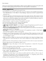
Dear Customer,
Thank you for purchasing this Hendi appliance. Before using the appliance for the first time, please read
this manual carefully, paying particular attention to the safety regulations outlined below.
Safety regulations
• This appliance is not intended for household use.
• The appliance must only be used for the purpose for which it was intended and designed.
The manufacturer is not liable for any damage caused by incorrect operation and
improper use.
• Keep the appliance and electrical plug away from water and any other liquids. In the
event that the appliance should fall into water, immediately remove plug from the socket
and do not use until the appliance has been checked by a certified technician. Failure to
follow these instructions could cause a risk to lives.
• Never attempt to open the casing of the appliance yourself.
• Do not insert any objects in the casing of the appliance.
• Do not touch the plug with wet or damp hands.
•
Danger of electric shock! Do not attempt to repair the appliance yourself. In case of
malfunctions, repairs are to be conducted by qualified personnel only.
• Never use a damaged appliance! Disconnect the appliance from the electrical outlet and
contact the retailer if it is damaged.
• Warning! Do not immerse the electrical parts of the appliance in water or other liquids.
Never hold the appliance under running water.
• Regularly check the power plug and cord for any damage. If the power plug or power cord
is damaged, it must be replaced by a service agent or similarly qualified persons in order
to avoid danger or injury.
• Make sure the cord does not come in contact with sharp or hot objects and keep it away
from open fire. To pull the plug out of the socket, always pull on the plug and not on the
cord.
•
Ensure that the cord (or extension cord) is positioned so that it will not cause a trip hazard.
• Always keep an eye on the appliance when in use.
•
Warning! As long as the plug is in the socket the appliance is connected to the power
source.
• Turn off the appliance before pulling the plug out of the socket.
• Never carry the appliance by the cord.
• Do not use any extra devices that are not supplied along with the appliance.
• Only connect the appliance to an electrical outlet with the voltage and frequency
mentioned on the appliance label.
• Connect the power plug to an easily accessible electrical outlet so that in case of
emergency the appliance can be unplugged immediately. To completely switch off the
appliance pull the power plug out of the electrical outlet.
• Always turn the appliance off before disconnecting the plug.
3
NLEN

4
EN
• Never use accessories other than those recommended by the manufacturer. Failure to do
so could pose a safety risk to the user and could damage the appliance. Only use original
parts and accessories.
• This appliance is not intended for use by persons (including children) with reduced
physical, sensory or mental capabilities, or lack of experience and knowledge.
• This appliance must not be used by children under any circumstances.
• Keep the appliance and its cord out of reach of children.
• Always disconnect the appliance from the mains if it is left unattended or is not in use,
and before assembly, disassembly or cleaning.
• Never leave the appliance unattended during use.
Special Safety Regulations
• Use the machine only as described in this manual.
• This machine should be operated and installed by specialized trained personnel in the
kitchen of the food industry such as catering, bakery, pizza, pastry, etc.
• All maintenance, installation and repair works should be performed by specialized
trained authorized technicians.
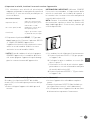
• An equipotential bonding terminal is provided at the rear side of the appliance
to allow cross bonding with other equipment.
• Do not place the machine on a heating object (gasoline, electric, charcoal cooker, etc.)
Keep the appliance away from any hot surfaces and open flames. Always operate the
machine on a level, stable, clean, heat-resistant and dry surface.
• Do not use the machine near explosive or flammable materials, credit cards, magnetic
discs or radios.
• Wear protective clothing, mask, or protective glasses if necessary during operation.
• This machine is not intended to be operated by means of an external timer or separate
remote-control system.
• Never bypass any safety interlocks on the machine.
• WARNING: Keep all ventilation openings in the appliance clear of obstruction.
• WARNING: ALWAYS switch off the machine and unplug from electrical power supply
before cleaning, maintenance or changing attachments.
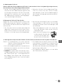
• Allow at least 30 cm spacing around the appliance for ventilation purpose during use.
• Caution! Securely route the power cord if necessary in order to prevent unintentional
pulling or contact with the heating surface.
• WARNING! ALWAYS keep hands, long hair and loose clothing away from the moving
parts.
• Do not put hands into the guarded area and mixing bowl when the machine is in opera
-
tion.
• Do not load too much ingredients in order to prevent overflow of the food products. Maxi
-
mum capacity of the bowl is 10 litres for 222836, 222966 and 20 litres for 222843, 222973.
• Do not wash the machine with water or a waterjet. Washing with water can cause leakage
and increase the risk of electric shock. No parts are dishwasher safe.

5
EN
• Do not clean or store the machine unless it is completely cooled down.
• Special care should be taken when moving or transporting the machine as it is too heavy.
With at least 2 people or using a trolley for assistance. Move the machine slowly, carefully
and never be inclined over 45°C.
Intended use
• The appliance is intended for professional use
and can be operated only by qualified personnel.
• The appliance is designed for mixing, kneading
and emulsifying/whipping food products operat-
ed in the food industry and shops. Any other use
may lead to damage to the appliance or personal
injury.
• Operating the appliance for any other purpose
shall be deemed as a misuse of the device. The
user shall be solely liable for improper use of the
device.
Grounding installation
This appliance is classified as protection class I
appliance and must be connected to a protective
ground. Grounding reduces the risk of electric
shock by providing an escape wire for the electric
current. This appliance is equipped with a cord
having a grounding wire with a grounding plug. The
plug must be plugged into an outlet that is properly
installed and grounded.
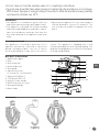
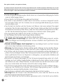
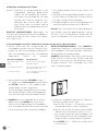
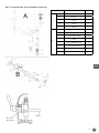
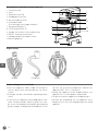
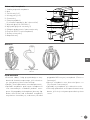
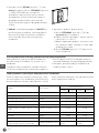
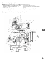
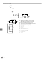
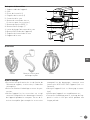
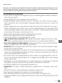
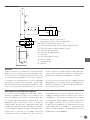
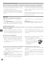
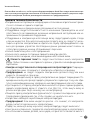
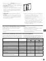
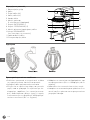
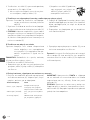
Main parts of the machine
1. Rigid stand support
2. Bowl
3. Bowl clamp (x2)
4. Bowl handles (x2)
5. Bowl guard
6. Speed control lever
(3 settings for 3 attachments)
7. ON button (GREEN, I)
8. STOP button (RED, O)
9. Bowl lift / lower handle
10.RESET button (at the rear)
11.Bowl guard handle
12.Bowl cradle
1
2
4
6
5
3
12
11
7
8
9
10
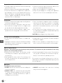
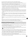
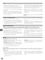
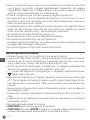
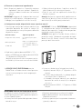
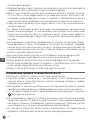
Attachments

6
EN
Preparations before installation
• Carefully unbolt the machine from the skid using
wrench if necessary.
• Remove all protective packaging and wrapping.
• Check the machine for completeness and trans-
port damages. In case of incomplete delivery (e.g.
Whisk, flat beater and dough hook) or damage,
contact supplier immediately. DO NOT use the
machine. (See ==> Warranty).
• Clean the machine and attachments before use
(See ==> Cleaning and Maintenance).
• Make sure the appliance is completely dry.
• Keep the packaging for storing your appliance
when not in use for an extended period of time.
Installation
• Read this manual thoroughly and carefully before
installation and operation.
• Ensure the machine is placed in a dry area that
have sufficient strength surface to support with
no any obstruction during operation nearby.
• Ensure that the electrical power supply corre-
sponds with the rating label on the machine.
• There should have adequate space around the
machine for the operator to operate. It should be
clean and free from obstructions, e.g. Nothing
placed on or around the machine, such as scrap-
ers, knives etc.
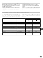
• Do not wear loose fitting clothing such as scarf,
etc and long hair should be tied up and keep away
from the moving parts.
CAUTION! Never bypass any safety switch.
Transportation and handling
• Do not move the machine while it is under op-
eration.
• Unplug the machine, remove the bowl (2) and all
attachments (whisk, flat beater or dough hook)
when moving the machine.
• Hold the base of the machine (1) when moving to
have better support.
• With at least 2 people or using trolley for assis-
tance to move the machine due to heavy weight.
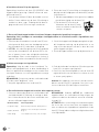
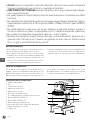
Special safety features
Attention: This machine has the following 3 safety switches. The machine only be started with all the safety
switches are at the proper positions.
• Bowl position safety switch: The machine can be
started up once the bowl is positioned at the cor-
rect position.
• Bowl guard (5) safety switch: The machine can
only be started up once the bowl guard (5) is in
the closed position.
• Bowl lift up handle (9) safety switch: The machine
can only be started up once the bowl lift up han-
dle (9) is located in the upwards position.
Do not wear loose fitting clothing such as scarf, etc
and long hair should be tied up and keep away from
the moving parts
Operation
To avoid serious personal injury:
• DO NOT operate the machine without reading the
instruction manual.
• ALWAYS STOP the machine by pressing RED
“O” button (8) and unplug from electrical power
supply before cleaning, maintenance, repair or
changing any attachments.
• ALWAYS keep hands, hair and loose clothing
away from the moving parts.

7
EN
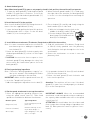
a) About the bowl guard
Note: When bowl guard (5) is open or not properly closed in lock position, the machine will not operate.
1. To open the bowl guard (5), hold the bowl guard
handle (11) and rotate it clockwise. To close the
bowl guard (5), hold the bowl guard handle (11)
and rotate it anti-clockwise.
2. When the bowl guard handle (11) is lined up at
the right side of the machine, the bowl guard (5)
is in the is in the rocked position and ready for
operation.
b) Install the bowl (2) to the machine
Note: Install the bowl (2) BEFORE fixing the attach-
ments. Use the supplied bowl (2) only.
1. Lower the bowl by pulling the bowl lift-up lever
(9) downwards until it stops. So that the bowl
cradle (12) is in a lower position.
2. Place the bowl (2) carefully and slowly using the
bowl handles (4) at 2 sides and
i) With the locking pin into the hole at the
middle of the bowl cradle (12) and
ii) Secure the bowl (2) by pull each
bowl clamp (3) forward until the
bowl (2) is locked tight.
c) Install different attachments (Flat beater, Dough hook or Whisk) to the machine
Note: It is more convenient and easier to install the
attachments prior to adding the ingredients
into the bowl (2).
1. Rotate the bowl guard (5) clockwise gently with
the bowl guard handle (6), so that it is in the open
position.
2. CAUTION! Use excessive force to open or close
the bowl guard (5) may damage the safety lock
micro switch. Be careful when open or close the
bowl guard (5).
3. Slide the attachments (Flat beater, Dough hook
or Whisk) slowly upwards onto the planetary
shaft fitting the shaft pin through the slot in the
attachments.
4. Rotate the attachments to secure it onto the
planetary shaft.
d) Pouring and mixing ingredients
Note: Follow the “Mixing ingredients capacity” ta-
ble in this manual. Overloading will lead to
overflow or damage to the machine.
IMPORTANT: Make sure the speed control lever (6)
is set at the “dough hook” position.
1.
Add all the appropriate ingredients into the bowl (2).
2. Lift upwards the bowl lift lever (9) until the bowl
(2) locks into the position.
3. Rotate the bowl guard (5) anti-clockwise and
locks into the position.
Attention: The machine will not start if the bowl
guard (5) is open / not closed properly or the bowl
(2) is at the lower position.
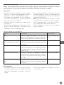
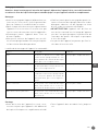
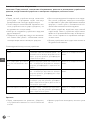
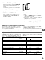
e) Set the speed, attachment & start up the machine
1. Select the appropriate speed by lifting or low-
ering the speed control lever (6). Three fixed
speeds are available for different attachments:
Rotation speed Type of ingredient
Dough hook (Low)
Heavy: Mixing pizza, bread,
pasta and
Flat beater (Medium)
Medium: 2nd stage of mix
-
ing for donut dough, etc.
Whisk (High) Light: Whipping cream, egg
whites, meringue.
IMPORTANT: ALWAYS follow the recommended
attachment used and speed setting according to
the capacity table and indication next to the speed
control lever (6).
ATTENTION: Be careful about the risk of dust and
flour escape when slitting of bags of ingredient into
bowl (2). Wear protective mask or glasses if nec-
essary.

8
EN
2. After that, press the GREEN “I” button (7) to
switch ON the machine. Press RED “O” button
(8) to STOP the machine.
The machine will rotate in clockwise direction
for item 222843 whereas and anti-clockwise
direction for 222836.
3. CAUTION! ALWAYS STOP the machine BEFORE
changing speeds. Failure to do so may damage
the internal gear construction.
4.
To change the speed during the operation:
a)
Press the RED “O” button (8) to STOP the ma-
chine.
b) Unplug the machine and change the attach-
ment. [See ==> part c)].
c)
Change the speed by raising or lowering the speed
control lever (6) with the correct attachment.
d) Press the GREEN “I” button (7) to restart the
machine.
RESET the Hi-limiter (thermal cut-out)
Please note that the RESET button (10) is located
at the rear of the machine in order to prevent
overheated.
• Unplug the machine from the electrical power
outlet first.
• Let the machine to cool down completely.
• Press the RESET button (10) of the Hi-limiter
(thermal cut-out)
• Then, plug into the electrical power outlet and
start up the machine again.
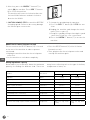
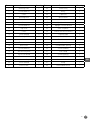
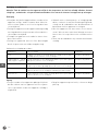
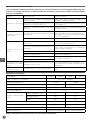
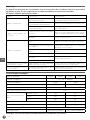
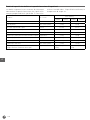
Mixing ingredients capacity
Below table is just a reference about the maximum
quantity for making the different food. There are
many factors affecting such as the type of the flour,
temperature of water, etc.
Product Attachment
Max. quantity
222836 222966 222843 222973
Egg white Whisk 1,0 kg 1,5 kg
Mashed potato Flat beater 2,0 kg 2,5 kg
Meringue (Qty of water) Whisk 1,5 litre 2,0 litre
Waffle or pancake batter Flat beater 2,5 litres 3,0 litre
Whipped cream Whisk 3,5 litres 4,0 litre
Pizza dough (Medium, 50% water) Dough hook 2,0 kg 2,5 kg
Pizza dough (Thick, 60% water) Dough hook 2,5 kg 3,0 kg
Sponge cake Whisk 1,5 kg 2,0 kg
Pie Dough Flat beater 2,0 kg 2,5 kg
Bread or Roll Dough (Light/ Medium, 60% water) Dough hook Water 1,5 kg/ Flour
2,5 kg
Water 3,0 kg/ Flour
5,0kg

9
EN
Cleaning and Maintenance
Attention: Always unplug the appliance from the electrical power outlet and let it cool down completely
before cleaning, maintenance, repair & storage.
Cleaning
• Always remove all the attachments before easy
cleaning, otherwise it will become stuck on the
shaft and difficult to remove later.
• Clean the machine and its attachments thor-
oughly after each use and ensure all food resi-
dues are removed.
• Never immerse the appliance in water or other
liquids.
• Clean the surface with a slightly damp cloth or
sponge with some mild soap solution.
• Never use abrasive sponges, detergents, steel
wool or metallic utensils to clean the interior or
exterior parts of the appliance.
• DO NOT wash the appliance with water or water-
jet. Washing with water can cause leakage and
increase the risk of electric shock.
• No any parts or attachments are dishwasher
safe.
Recommended cleaning procedure:
Parts How to clean Frequency
Bowl Using a sponge or damp cloth with
mild soap and water, rinse, sanitize
and dry thoroughly.
Clean after each use
Attachments (Dough hook, beater
and whisk)
Hand wash using mild soap and wa-
ter, rinse, sanitize and dry thoroughly.
Clean after each use
Bowl guard Hand wash using a sponge or damp
cloth with mild soap and water, rinse,
sanitize and dry thoroughly.
Clean after each use
Outer surface Wipe with a clean damp cloth using
soap and water, rinse, sanitize and
dry. Do not use water jet.
Twice a week
Planetary Shaft Wipe with a clean damp cloth using
soap and water, rinse, sanitize and
dry.
Clean after each use
Storage
• Before storage, always make sure the appliance
has already been disconnected from the electri-
cal outlet and cooled down completely.
• Store the appliance in a cool, clean and dry place.

10
EN
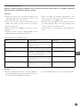
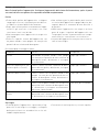
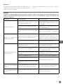
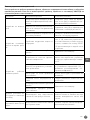
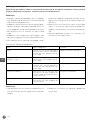
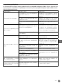
Troubleshooting
If the machine does not function properly, please check the below table for the solution. If you are still una-
ble to solve the problem, please contact the supplier/service provider. DO NOT repair yourself.
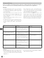
Problems Possible causes Possible solution
Machine do not start run
-
ning
Bowl guard (5) is not in properly closed
position.
Rotate the bowl guard (5) to the right
until fully closed properly.
Bowl (2) is not raised to the proper loca
-
tion.
Raise the bowl (2) to the correct position
by using the level (9).
The power plug is not connected properly. Check to make sure the power plug is
connected properly.
Machine stops during op
-
eration
Internal overload activates to prevent
overheat.
Press RED, “O” button (8), unplug the
machine, leave for cook down complete-
ly, press RESET button (10) at the back.
Damage or broken transmission belt Check with the supplier
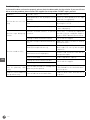
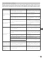
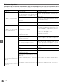
Machine sound too noisy
Machine is not placed on a horizontal sur
-
face.
Adjust the surface or move to another
horizontal surface.
Bowl (2) is not placed correctly.
Make sure the bowl (2) is placed into the
bowl cradle (12) correctly with the guid
-
ed pins (3).
Attachments not fitted properly.
Remove and install the attachments
into position again.
Bowl is overloaded. Reduce ingredients capacity.
Damaged or worn transmission belt.
Check with the supplier.
Planetary gear needs lack of lubricant.
Attachments cannot install
onto the planetary shaft
easily
Lack of lubricant and / or cleaning of the
planetary shaft required.
Wipe planetary shaft with a clean damp
cloth and lubricate the shaft with miner
-
al oil or grease.
Bowl lift / lower handle (9)
not operation easily
Lack of lubricant on the bowl slides.
Lubricate bowl slides with mineral oil
or grease.

11
EN
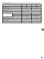
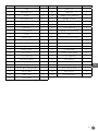
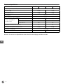
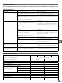
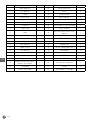
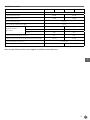
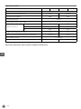
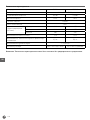
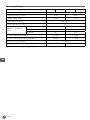
Technical specification
Item no. 222836 222966 222843 222973
Operating voltage and frequency 220 – 240 V~ 50/60Hz
Rated input power 600W 1100W
Net weight (approx.) 53kg 78kg
Protection class Class I
Waterproof protection class IP21
Rotation speed (r.p.m.)
Dough hook 148 197
Flat beater 244 317
Whisk 480 462
Maximum bowl capacity 10L 20L
Maximum amount flour mixing 2,5 kg 5,0 kg
Max noise level < 70 dB (A)
Outer dimension 480 x 400 x (H) 630mm 560 x 500 x (H) 880mm
Remark: Technical specification is subjected to change without prior notification.

12
EN
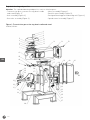
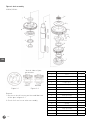
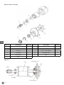
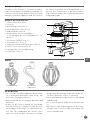
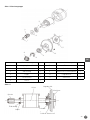
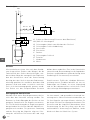
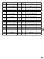
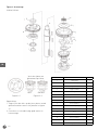
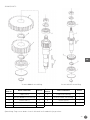
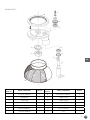
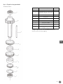
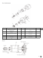
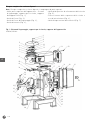
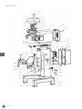
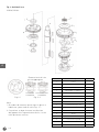
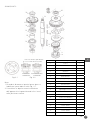
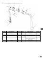
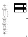
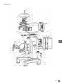
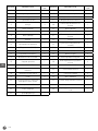
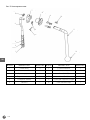
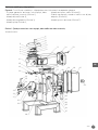
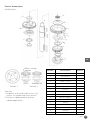
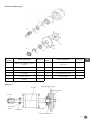
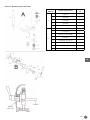
Exploded drawing and part list
Attention: The exploded drawing and part list consists of below parts:
- Transmission gear system at the top, bowl cradle
and stand (Figure 1);
- Axle assembly (Figure 2);
- Gear axle assembly (Figure 3);
- Motor assembly (Figure 4);
- Bowl lift up assembly (Figure 5);
-
Bowl guard turning plate and mixing axle (Figure 6);
- Speed control assembly (Figure 7)
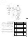
Figure 1: Transmission gear at the top, bowl cradle and stand
222836/222966:
1
41
25
40
39
33
32
31
30
29
28
27
26
25
24
23
22
42
36 38
37
35
34
2
3
4
5
6
7
8
9
10
11
12
13 14 15
16
17 18
19 20 21

13
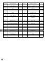
EN
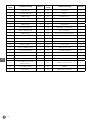
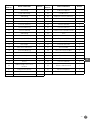
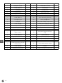
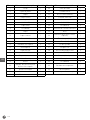
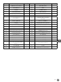
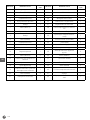
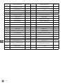
Part no. Part name Quantity Part no. Part name Quantity
1 Bearing cover 1 22 Timer relay 1
2 Screw (M6X16) 4 23 Relay 2
3 Cover 1 24 Capacitor 1
4 Bearing 6202 1 25 Microswitch 3
5 Center cover 1 26 Cable joint 1
6 Cover 2 27 Upright column 1
7 Screw (M5X16) 1 28 Upright column board 1
8 Top cover 1 29 Arm complete 1
9 Cover 1 30 Sleeve (for microswitch) 1
10 Screw (M5X8) 5 31 Cap nut (M8) 2
11 Bearing 6001 1 32 Nut (M8) 4
12 Cover 1 33 Bowl’s screw 2
13 Power switch 1 34 Fixed handle 2
14 Rear cover 1 35 Fixed handle spring 2
15 Screw (M6X35) 4 36 Screw (M8X60) 2
16 Anti mouse plate 1 37 Flat clamp 2
17 Electrical board 1 38 Screw (M6X16) 6
18 Transformer 1 39 Screw (M4X8) 2
19 Electric box sealing strips 1 40 Microswitch rack 2
20 Screw (M5X8) 4 41 Body 1
21 Electric box 1 42 Overloaded switch 1

14
EN
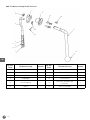
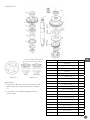
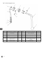
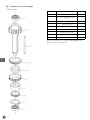
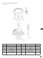
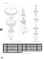
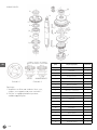
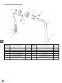
222843/222973:
5
6
7
8
9
10
11
12
13
14 15
16
17
8
21
45
20
22
23
24
30
31
32
3334
35
36
37
40
41
42
43
44
1
2
3
4
38
39
8
25
26
27
2829
44
1918

15
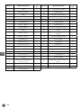
EN
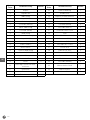
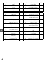
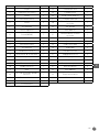
Part no. Part name Quantity Part no. Part name Quantity
1 Body 1 24 Cable joint 1
2 Bearing cover 1 25 Capacitor 1
3 Cover 2 26 Copper screw (M5X12) 1
4 Bearing (6003) 1 27 Upright column 1
5 Cover 3 28 Upright column board 1
6 Screw (M6X45) 1 29 Screw (M4X8) 2
7 Top cover 1 30 Screw (M6X16) 6
8 Screw (M5X8) 7 31 Upright column board 1
9 Cover 1 32 Arm 1
10 Center cover 1 33 Sleeve (for microswitch) 1
11 Bearing (6201) 2 34 Cap nut (M8) 2
12 Screw (M6X14) 4 35 Nut (M8) 2
13 Spring washer 6 4 36 Bowl’s screw 2
14 Power switch 1 37 Fixed handle 2
15 Rear cover 1 38 Fixed handle spring 2
16 Screw (M6X35) 4 39 Screw (M8X60) 2
17 Anti mouse plate 1 40 Plastic block 1
18 Electrical board 1 41 Flat clamp 2
19 Relay 2 42 Screw (M8X25) 4
20 Electric box sealing strips 1 43 Microswitch rack 1
21 Electric box 1 44 Microswitch 2
22 Timer relay 1 45 Overload switch 1
23 Transformer 1

16
EN
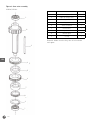
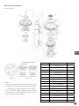
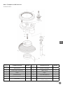
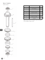
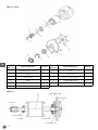
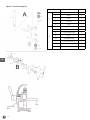
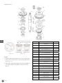
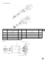
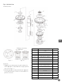
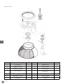
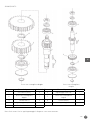
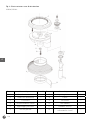
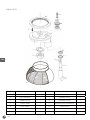
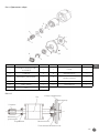
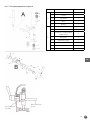
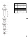
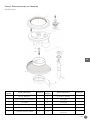
Figure 2: Axle assembly
222836/222966:
1
2
3
4
5
6
7
8
9
10
11
12
13
14
15
16
Vertical sides of jaws
on another.
RIGHT
WRONG
Figure 2-1 Figure 2-2
Remark:
1. Be sure to install correct position and lubricate
all the pins in figure 2-1.
2. Check if oil seal occur after reassembly.
Part no. Part name Quantity
1 Cover 1
2 Oil seal 1
3 Bearing (6204) 1
4 Coupler gear 1
5 bearing 1
6 Central axle 1
7 Coupler 1
8 Bearing 1
9 Small gear ring 1
10 Divider ring 1
11 Actuator 1
12 Spring 1
13 Roller 1
14 Large gear ring 1
15 Cover 1
16 Bearing (6001) 1

17
EN
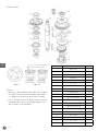
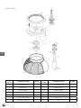
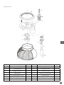
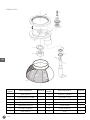
222843/222973:
9
8
7
6
4
3
2
5
1
20
16
10
11
12
13
15
14
17
18
19
Vertical sides of jaws
must face on another.
RIGHT
WRONG
Figure 2-1 Figure 2-2
Remark:
1. Be sure to install correct position and lubricate
all the pins in figure 2-1.
2. Check if oil seal occur after reassembly.
Part no. Part name Quantity
1 Cover 1
2 Roller 1
3 Spring 1
4 Actuator 1
5 Gear ring 1
6 Divider ring 1
7 Upper gear 1
8 Bearing ring 1
9 Clutch ring 1
10 Bearing ring 1
11 Lower gear 1
12 Ring 1
13 Bearing (6205) 1
14 Oil seal (30X45X10) 1
15 Stand-off 1
16 Central axle 1
17 Key (6X14) 1
18 Key (5X35) 1
19 Key (6X30) 1
20 Bearing (6003) 1

18
EN
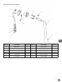
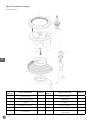
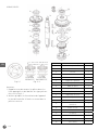
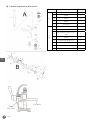
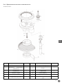
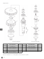
Figure 3: Gear axle assembly
222836/222966:
1
2
3
4
5
6
7
8
9
1
Part no. Part name Quantity
1 Bearing (6001) 2
2 High speed gear axle 1
3 Key (5X58) 1
4 Top gear 1
5 Small stand-off 1
6 Gear (lower) 1
7 Large stand-off 1
8 Bottom gear 1
9 Circlip 1
Remark: Make sure the keys are all inserted to
each gear.

19
EN
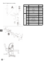
222843/222973:
1
2
3
1
5
5
4
6
Dual gear axle
1
7
8
9
5
1
Single gear axle
Part no. Part name Quantity Part no. Part name Quantity
1 Bearing (6201) 4 6 Lower gear 1
2 Dual geared axle 1 7 Single geared axle 1
3 Key (5X11) 2 8 Key (5X14) 1
4 Upper gear 1 9 Gear 1
5 Circlip 3
Remark: Make sure the keys are all inserted to each gear.

20
EN
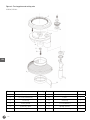
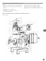
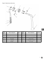
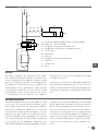
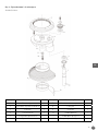
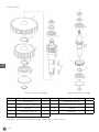
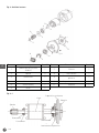
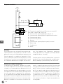
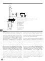
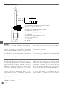
Figure 4: Motor assembly
1
2
3
4
5
6
7
8
9
4
10
11
Part no. Part name Quantity Part no. Part name Quantity
1 Stop ring (222843 only) 1 7 Rotor 1
2 Spiral 2 8 Switch 1
3 Oil seal 1 9 Plastic switch plate 1
4 Bearing 1 10 Bearing cover 1
5 Key (4x22) 1 11 Fan 1
6 Axle 1
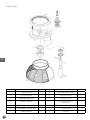
Figure 4-1
Axle
Bearing
Oil seal
Bearing cover
Switch plastic
Switch
Spiral
Fan
Strona się ładuje...
Strona się ładuje...
Strona się ładuje...
Strona się ładuje...
Strona się ładuje...
Strona się ładuje...
Strona się ładuje...
Strona się ładuje...
Strona się ładuje...
Strona się ładuje...
Strona się ładuje...
Strona się ładuje...
Strona się ładuje...
Strona się ładuje...
Strona się ładuje...
Strona się ładuje...
Strona się ładuje...
Strona się ładuje...
Strona się ładuje...
Strona się ładuje...
Strona się ładuje...
Strona się ładuje...
Strona się ładuje...
Strona się ładuje...
Strona się ładuje...
Strona się ładuje...
Strona się ładuje...
Strona się ładuje...
Strona się ładuje...
Strona się ładuje...
Strona się ładuje...
Strona się ładuje...
Strona się ładuje...
Strona się ładuje...
Strona się ładuje...
Strona się ładuje...
Strona się ładuje...
Strona się ładuje...
Strona się ładuje...
Strona się ładuje...
Strona się ładuje...
Strona się ładuje...
Strona się ładuje...
Strona się ładuje...
Strona się ładuje...
Strona się ładuje...
Strona się ładuje...
Strona się ładuje...
Strona się ładuje...
Strona się ładuje...
Strona się ładuje...
Strona się ładuje...
Strona się ładuje...
Strona się ładuje...
Strona się ładuje...
Strona się ładuje...
Strona się ładuje...
Strona się ładuje...
Strona się ładuje...
Strona się ładuje...
Strona się ładuje...
Strona się ładuje...
Strona się ładuje...
Strona się ładuje...
Strona się ładuje...
Strona się ładuje...
Strona się ładuje...
Strona się ładuje...
Strona się ładuje...
Strona się ładuje...
Strona się ładuje...
Strona się ładuje...
Strona się ładuje...
Strona się ładuje...
Strona się ładuje...
Strona się ładuje...
Strona się ładuje...
Strona się ładuje...
Strona się ładuje...
Strona się ładuje...
Strona się ładuje...
Strona się ładuje...
Strona się ładuje...
Strona się ładuje...
Strona się ładuje...
Strona się ładuje...
Strona się ładuje...
Strona się ładuje...
Strona się ładuje...
Strona się ładuje...
Strona się ładuje...
Strona się ładuje...
Strona się ładuje...
Strona się ładuje...
Strona się ładuje...
Strona się ładuje...
Strona się ładuje...
Strona się ładuje...
Strona się ładuje...
Strona się ładuje...
Strona się ładuje...
Strona się ładuje...
Strona się ładuje...
Strona się ładuje...
Strona się ładuje...
Strona się ładuje...
Strona się ładuje...
Strona się ładuje...
Strona się ładuje...
Strona się ładuje...
Strona się ładuje...
Strona się ładuje...
Strona się ładuje...
Strona się ładuje...
Strona się ładuje...
Strona się ładuje...
Strona się ładuje...
Strona się ładuje...
Strona się ładuje...
Strona się ładuje...
Strona się ładuje...
Strona się ładuje...
Strona się ładuje...
Strona się ładuje...
Strona się ładuje...
Strona się ładuje...
Strona się ładuje...
Strona się ładuje...
Strona się ładuje...
Strona się ładuje...
Strona się ładuje...
Strona się ładuje...
Strona się ładuje...
Strona się ładuje...
Strona się ładuje...
Strona się ładuje...
Strona się ładuje...
Strona się ładuje...
Strona się ładuje...
Strona się ładuje...
Strona się ładuje...
Strona się ładuje...
Strona się ładuje...
Strona się ładuje...
Strona się ładuje...
Strona się ładuje...
Strona się ładuje...
Strona się ładuje...
Strona się ładuje...
Strona się ładuje...
Strona się ładuje...
Strona się ładuje...
Strona się ładuje...
Strona się ładuje...
Strona się ładuje...
Strona się ładuje...
Strona się ładuje...
Strona się ładuje...
Strona się ładuje...
Strona się ładuje...
Strona się ładuje...
Strona się ładuje...
Strona się ładuje...
Strona się ładuje...
Strona się ładuje...
Strona się ładuje...
Strona się ładuje...
Strona się ładuje...
Strona się ładuje...
Strona się ładuje...
Strona się ładuje...
Strona się ładuje...
Strona się ładuje...
Strona się ładuje...
Strona się ładuje...
Strona się ładuje...
Strona się ładuje...
Strona się ładuje...
Strona się ładuje...
Strona się ładuje...
Strona się ładuje...
Strona się ładuje...
Strona się ładuje...
Strona się ładuje...
Strona się ładuje...
Strona się ładuje...
Strona się ładuje...
Strona się ładuje...
Strona się ładuje...
Strona się ładuje...
Strona się ładuje...
Strona się ładuje...
Strona się ładuje...
Strona się ładuje...
Strona się ładuje...
Strona się ładuje...
Strona się ładuje...
Strona się ładuje...
Strona się ładuje...
Strona się ładuje...
-
 1
1
-
 2
2
-
 3
3
-
 4
4
-
 5
5
-
 6
6
-
 7
7
-
 8
8
-
 9
9
-
 10
10
-
 11
11
-
 12
12
-
 13
13
-
 14
14
-
 15
15
-
 16
16
-
 17
17
-
 18
18
-
 19
19
-
 20
20
-
 21
21
-
 22
22
-
 23
23
-
 24
24
-
 25
25
-
 26
26
-
 27
27
-
 28
28
-
 29
29
-
 30
30
-
 31
31
-
 32
32
-
 33
33
-
 34
34
-
 35
35
-
 36
36
-
 37
37
-
 38
38
-
 39
39
-
 40
40
-
 41
41
-
 42
42
-
 43
43
-
 44
44
-
 45
45
-
 46
46
-
 47
47
-
 48
48
-
 49
49
-
 50
50
-
 51
51
-
 52
52
-
 53
53
-
 54
54
-
 55
55
-
 56
56
-
 57
57
-
 58
58
-
 59
59
-
 60
60
-
 61
61
-
 62
62
-
 63
63
-
 64
64
-
 65
65
-
 66
66
-
 67
67
-
 68
68
-
 69
69
-
 70
70
-
 71
71
-
 72
72
-
 73
73
-
 74
74
-
 75
75
-
 76
76
-
 77
77
-
 78
78
-
 79
79
-
 80
80
-
 81
81
-
 82
82
-
 83
83
-
 84
84
-
 85
85
-
 86
86
-
 87
87
-
 88
88
-
 89
89
-
 90
90
-
 91
91
-
 92
92
-
 93
93
-
 94
94
-
 95
95
-
 96
96
-
 97
97
-
 98
98
-
 99
99
-
 100
100
-
 101
101
-
 102
102
-
 103
103
-
 104
104
-
 105
105
-
 106
106
-
 107
107
-
 108
108
-
 109
109
-
 110
110
-
 111
111
-
 112
112
-
 113
113
-
 114
114
-
 115
115
-
 116
116
-
 117
117
-
 118
118
-
 119
119
-
 120
120
-
 121
121
-
 122
122
-
 123
123
-
 124
124
-
 125
125
-
 126
126
-
 127
127
-
 128
128
-
 129
129
-
 130
130
-
 131
131
-
 132
132
-
 133
133
-
 134
134
-
 135
135
-
 136
136
-
 137
137
-
 138
138
-
 139
139
-
 140
140
-
 141
141
-
 142
142
-
 143
143
-
 144
144
-
 145
145
-
 146
146
-
 147
147
-
 148
148
-
 149
149
-
 150
150
-
 151
151
-
 152
152
-
 153
153
-
 154
154
-
 155
155
-
 156
156
-
 157
157
-
 158
158
-
 159
159
-
 160
160
-
 161
161
-
 162
162
-
 163
163
-
 164
164
-
 165
165
-
 166
166
-
 167
167
-
 168
168
-
 169
169
-
 170
170
-
 171
171
-
 172
172
-
 173
173
-
 174
174
-
 175
175
-
 176
176
-
 177
177
-
 178
178
-
 179
179
-
 180
180
-
 181
181
-
 182
182
-
 183
183
-
 184
184
-
 185
185
-
 186
186
-
 187
187
-
 188
188
-
 189
189
-
 190
190
-
 191
191
-
 192
192
-
 193
193
-
 194
194
-
 195
195
-
 196
196
-
 197
197
-
 198
198
-
 199
199
-
 200
200
-
 201
201
-
 202
202
-
 203
203
-
 204
204
-
 205
205
-
 206
206
-
 207
207
-
 208
208
-
 209
209
-
 210
210
-
 211
211
-
 212
212
-
 213
213
-
 214
214
-
 215
215
-
 216
216
-
 217
217
-
 218
218
-
 219
219
-
 220
220


Hendi 222836 Instrukcja obsługi
- Typ
- Instrukcja obsługi
- Niniejsza instrukcja jest również odpowiednia dla
w innych językach
- italiano: Hendi 222836 Manuale utente
- Deutsch: Hendi 222836 Benutzerhandbuch
- français: Hendi 222836 Manuel utilisateur
- English: Hendi 222836 User manual
- русский: Hendi 222836 Руководство пользователя
- Nederlands: Hendi 222836 Handleiding
- română: Hendi 222836 Manual de utilizare
Powiązane artykuły
Inne dokumenty
-
Kenwood KM240 Prospero Stand Mixer Instrukcja obsługi
-
Kenwood KM240 series Instrukcja obsługi
-
Kenwood KHH301WH Instrukcja obsługi
-
Kenwood KMX750AB Instrukcja obsługi
-
Kenwood Multione KHH30 Instructions Manual
-
Kenwood HM680 Instrukcja obsługi
-
ELDOM IK2901 IDEAL Instrukcja obsługi
-
Goobay 58531 Double Monitor Mount Instrukcja obsługi
-
-
Lund 67641 Instrukcja obsługi