
WATER SOFTENER
ZMIĘKCZACZ DO WODY
User manual
Instrukcja obsługi
You should read this user manual carefully before
using the appliance.
Przed uruchomieniem urządzenia należy koniecznie
dokładnie przeczytać niniejszą instrukcję obsługi.
You should read this user manual carefully before
using the appliance.
Przed uruchomieniem urządzenia należy koniecznie
dokładnie przeczytać niniejszą instrukcję obsługi.
Item: 230442
230459

2
EN
Keep this manual with the appliance.
Zachowaj instrukcję urządzenia.
For indoor use only.
Do użytku wewnątrz pomieszczeń.

3
EN
INDEX
1. IMPORTANT SAFETY REGULATIONS ..............................................................................................................4
2. HOW YOUR WATER SOFTENER WORKS .........................................................................................................5
3. CONTENTS .......................................................................................................................................................6
4. PREPARATION FOR INSTALLATION ...............................................................................................................6
5. INSTALLATION ................................................................................................................................................6
6. BEFORE FIRST SWITCHON............................................................................................................................8
7. OPERATING CYCLES OF THE DEVICE .............................................................................................................9
8. USAGE ............................................................................................................................................................11
9. CLEANING AND MAINTENANCE ..................................................................................................................16
10. TROUBLESHOOTING ...................................................................................................................................18
11. SPECIFICATION DATA ..................................................................................................................................19
12. WARRANTY ..................................................................................................................................................19
13. DISCARDING & ENVIRONMENT .................................................................................................................19

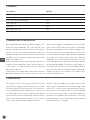
Dear Customer,
Thank you for purchasing this Hendi appliance. Before using the appliance for the first time, please read
this manual carefully, paying particular attention to the safety regulations outlined below.
1. IMPORTANT SAFETY REGULATIONS
• This appliance is intended for commercial use only and must not be used for
household use.
• The appliance must only be used for the purpose for which it was intended and
designed. The manufacturer is not liable for any damage caused by incorrect oper-
ation and improper use.
• Keep the appliance and electrical plug away from water and any other liquids. In
the event that the appliance should fall into water, immediately remove plug from
the socket and do not use until the appliance has been checked by a certified tech-
nician. Failure to follow these instructions could cause a risk to lives.
• Never attempt to open the casing of the appliance yourself.
• Do not insert any objects in the casing of the appliance.
• Do not touch the plug with wet or damp hands.
• Danger of electric shock! Do not attempt to repair the appliance yourself. In case
of malfunctions, repairs are to be conducted by qualified personnel only.
• Never use a damaged appliance! Disconnect the appliance from the electrical
outlet and contact the retailer if it is damaged.
• Warning! Do not immerse the electrical parts of the appliance in water or other
liquids. Never hold the appliance under running water.
• Regularly check the power plug and cord for any damage. If the power plug or
power cord is damaged, it must be replaced by a service agent or similarly qualified
persons in order to avoid danger or injury.
• Make sure the cord does not come in contact with sharp or hot objects and keep it
away from open fire. To pull the plug out of the socket, always pull on the plug and
not on the cord.
• Ensure that the cord (or extension cord) is positioned so that it will not cause a
trip hazard.
• Always keep an eye on the appliance when in use.
• Warning! As long as the plug is in the socket the appliance is connected to the
power source.
• Turn off the appliance before pulling the plug out of the socket.
• Never carry the appliance by the cord.
4
EN

5
EN
• Do not use any extra devices that are not supplied along with the appliance.
• Only connect the appliance to an electrical outlet with the voltage and frequency
mentioned on the appliance label.
• Connect the power plug to an easily accessible electrical outlet so that in case of
emergency the appliance can be unplugged immediately. To completely switch off
the appliance pull the power plug out of the electrical outlet.
• Always turn the appliance off before disconnecting the plug.
•Never use accessories other than those recommended by the manufacturer. Fail-
ure to do so could pose a safety risk to the user and could damage the appliance.
Only use original parts and accessories.
• This appliance is not intended for use by persons (including children) with reduced
physical, sensory or mental capabilities, or lack of experience and knowledge.
• This appliance must not be used by children under any circumstances.
• Keep the appliance and its cord out of reach of children.
• Always disconnect the appliance from the mains if it is left unattended or is not in
use, and before assembly, disassembly or cleaning.
• Never leave the appliance unattended during use.
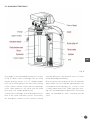
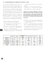
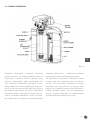
2. HOW YOUR WATER SOFTENER WORKS
Hard water flows to your household with a mains
pipe. It reaches the softener and flows through a
deposit of ion exchange resin which softens water.
At that time ion exchange process occurs, in the
course of which calcium and magnesium ions re-
sponsible for the hardness of water are captured by
the ion exchange resin and replaced with sodium
ions that dissolve well in water. Successively, sof-
tened water is delivered to the installation system
in your household.
A device programmed individually for your wa-
ter measures the quantity of water which flows
through. As soon as the exchange capacity of the
resin is reached, the device automatically (230459)
or semi-automatically (230442) carries out re-
generation of the resin with pre-prepared brine
(salt dissolved in water, stored in a brine tank). In
the course of regeneration, the device will draw a
programmed quantity of brine to the tank with ion
exchange resin. As a result, reverse-cycle ion ex-
change will occur.
The ion exchange resin will be “charged” with
sodium ions from salt, as well as will release the
previously captured ions of calcium and magne-
sium that, together with the rest of brine, will be
drained to sewage. After the regeneration process
is done, the device regains its ion exchange capa-
bilities and can soften water further. The process
of ion exchange allows to utilize the water softener
for a long period, whereas the regeneration of ion
exchange resin can be done multiple times, thanks
to which the expensive resin does not have to be
replaced. The only thing to be done is to refill salt
in the tank.

6
EN
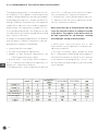
3. CONTENTS
Description Quantity
Softener body 1 unit
100 - 240 VAC voltage transformer 1 unit
2.5” wrench for the head flange 1 pc.
3/4” connector 2 pcs
3/4” seal 2 pcs
Worm drive hose clip 1 pc.
Non-collapsible hose 1 running metre
4. PREPARATION FOR INSTALLATION
After unpacking of the device, a power supply, a 2.5”
wrench for the head flange, 3/4” seals and 3/4” con-
nectors shall be taken out of the brine tank. Only the
special recesses in the housing shall be used to lift
and move the device around. The device shall not be
lifted by its electric cables or water hoses due to da
-
mage that might occur.
Before installing, ensure that water mains pressure
is above 1.5 bar and below 6.0 bar. Shall the pressu-
re be higher, a reducing valve shall be installed
upstream the device.
A location as close as possible to the water inlet of a
building shall be chosen (a water meter in case of
mains water supply or a hydrophore in case of own
water source/inlet) and in the vicinity of drainage.
Moreover, permanent electric power supply is ne
-
cessary, therefore a socket must be near. The surfa-
ce of installation must be stable and must withstand
the weight of the device filled with water. Ambient
temperature in the selected installation area shall
never drop below 5°C, otherwise the device may be
permanently damaged. The devices shall not be in
-
stalled in rooms with excessive air humidity. What is
more, the selected area shall be large enough to gu-
arantee free access to the device, as it requires pe-
riodical refilling of salt.
5. INSTALLATION
The connectors of the control head are marked as IN (inlet)
and OUT (outlet), looking from the front of the control head: IN
(inlet) on the right, OUT (outlet) on the left. The seals and con-
nectors provided shall be placed/fixed onto the connectors of
the control head. The water softener shall be connected to the
system with flexible hoses (not provided). A mechanical filter
shall be installed upstream the softener, of at least 50 mi-
crons, in order to protect the device against impurities.
A by-pass can be executed by means of regular valves, as indi-
cated in Fig. B. A turbine must be installed in a nipple fixed
onto the “OUT” connector of the control head. Before installa-
tion, make sure that the turbine rotates freely (e.g., by blowing
air into the water outlet). The device shall be installed by me-
ans of materials intended for water installations. In case of any
problems or doubts, contact a qualified installation company
or an authorized service company.

7
EN
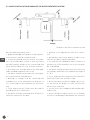
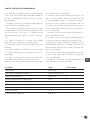
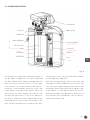
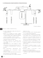
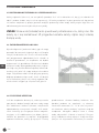
5.1. DIAGRAM OF THE DEVICE
Fig. B
An example of recommended installation is shown
in Fig. B. Water outlet to drainage from the head
may be done by means of a 1/2” flexible garden
hose. An overflow elbow on the side of the housing
of the softener shall be connected to the drainage
in the same manner as the outlet from the head
(e.g., with a 1/2” flexible garden hose).
Connections to drainage shall be done below their
level in the water treatment system. Particularly
the emergency overflow of the softener housing
shall be observed – any potential excess of water
will be drained gravitationally.
After all connections are done, fill the salt tank with
4kg of tablet salt. Salt shall be replenished as the
consumption thereof progresses, so that its level
is always above water level. Table 2 presents aver-
age salt consumption per regeneration. Exclusively
tablet salt intended for water softening shall be
used.

8
EN
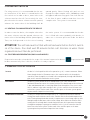
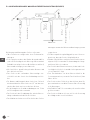
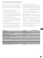
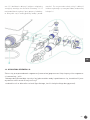
5.2. SAMPLE INSTALLATION DIAGRAM OF THE WATER TREATMENT SYSTEM
Diagram of the water treatment system
When installing and using the device:
• proper knowledge shall be possessed or profes-
sional services shall be commissioned
• it shall be ensured that the surface of installa-
tion is level and stable, as well as that the surface
will withstand the weight of the system filled with
water and salt tablets (in case of water softener)
• all connections shall be done in line with appli-
cable standards and provisions of law
• the device shall be connected to the existing wa-
ter installation with a flexible hose
• drainage to sewage shall be connected with
a flexible hose of the minimum hose diameter of
1/2”, of the length of the maximum of 6 m horizon-
tally
• solely and exclusively Teflon shall be used for
threaded seal-less connections
• the device shall be connected after all water in-
stallation connections are done
• perform resin regeneration after first connec-
tion
• periodically check water quality in order to en-
sure that the device operates properly
• use only the salt intended for water softeners, of
the purity of 99.5% minimum; use of fine salt pow-
der is prohibited
• the device shall be used in rooms of no excessive
air humidity and within the temperature range of
5 - 38°C
• use a reducing valve upstream the controller’s
water inlet if pressure exceeds 6.0 bar
• do not transport the device holding it by its hos-
es, the injector, the by-pass or other sensitive ele-
ments of the controller
• use the accessories and parts delivered by a dis-
tributor only
• protect the device against the access of children,
since they can damage or deregulate the controller.
100-240 VAC

9
EN
6. BEFORE FIRST SWITCHON
For safety reasons, it is recommended that the wa-
ter installation of the device is vented before the
first switch-on. In order to do so, water inlet to the
softener must be shut off. Consecutively, the sam-
pler valve after the water softener must be opened,
whereas the mains valve of the building shall be
opened gently. Water flowing will push air out
through the open sampler valve. A bubbling sound
will appear and water may gush. One shall wait un-
til the flow of water stabilizes and then close the
sampler valve. The system is now vented.
6.1. VENTING. FILLING WATER INTO THE DEVICE
In order to vent the device, the sampler valve after
the water softener must be opened, whereas the
mains valve of the building shall be opened gently.
Then, one shall proceed as in the case of venting
the entire system. It is recommended that the de-
vice is filled with water gradually, with breaks, in
order not to increase pressure inside the device
abruptly.
ATTENTION! The salt tank must be filled with salt and water before the first switch-
on of the device. One shall wait 30 minutes before salt dissolves in water. Resin
regeneration must then be performed.
6.2. FIRST RESIN REGENERATION (ONLY 230459 MODEL)
Regeneration must be activated with the usage of the manual regeneration button. Regeneration will
be done automatically. After it finishes, the device is ready to operate.
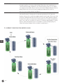
7. OPERATING CYCLES OF THE DEVICE
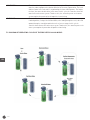
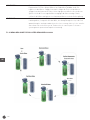
In serve the device is in the position of the first operation cycle, i.e. water treatment. Water
flows though the device. Raw water enters the container with resin through the
controller, flows through the resin and is directed upwards, through a distribution
pipe, to the controller and further to the system.
BACKWASH
The device is in the position of the second operation cycle - anti-current rinse
(backwash). Raw water enters the container with the filter bed through an inlet valve and
is directed downwards with a central pipe. Water flows through the resin, rinses it and
fluffs it, and then is directed to sewage. In this cycle the controller shuts off water inlet
to the water system. Thanks to which the controller protects the water system against
the penetration of impurities from rinsing.
BRINE DRAW SLOW RINSE T
he device in the position of third operation cycle - regeneration with brine and slow
rinsing. Raw water with brine enters to the container with the filter bed through an inlet
valve. Flowing through the bed in the tank, it regenerates its ion exchange capacity. After
flowing through the bed, water is directed to sewage. After all brine in the brine tank is
used up, the ion exchange bed is rinsed slowly with water, which guarantees thorough
rinsing brine and proper regeneration conditions. In this cycle the controller shuts off
water inlet to the water system. Thanks to which the controller protects the water
system against the penetration of impurities from rinsing.

10
EN
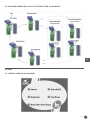
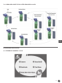
BRINE REFILL The device is in the position of fourth operation cycle - filling the salt tank with
water in order to prepare the solution of brine for the next regeneration. The level
of brine (water in the salt tank) is regulated by the time of filling water. The longer
the time, the more salt dissolves in the water. In this cycle the controller shuts off
water inlet to the water system. Thanks to this, the controller protects the water
system against the penetration of impurities from rinsing.
FAST RINSE
The device is in the position of fifth operation cycle - fast rinsing of the resin to remove any
remaining of brine, setting of the filter bed. Water, after flowing through the resin, is directed
upwards through a central pipe and further to the release to sewage. In this cycle the
controller shuts off water inlet to the water system. Thanks to this, the controller protects the
water system against the penetration of impurities from rinsing.
7.1. DIAGRAM OF OPERATING CYCLES OF THE DEVICE FOR 230442 MODEL

11
EN
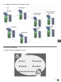
7.2. DIAOGRAM OPERATING CYCLES OF THE DEVICE FOR 230459 MODEL
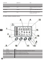
8. USAGE
8.1. CONTROL PANEL IN 230442 MODEL

12
EN
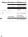
Mode Operation cycle Description
Inserve First water treatment
Backwash Second anti-current rinse
Brine & Slow Rinse Third regeneration with brine and slow
rinsing
Brine Refill Fourth filling the salt tank with water
Fast Rinse Fifth fast rinsing of the resin
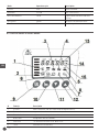
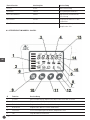
8.2.
CONTROL PANEL IN
230459 MODEL
# Funkcja Description
1 In serve water treatment, indicates water flow through the device;
2 Back wash regeneration reverse rinse of the resin;
3 Brine & slow rinse regeneration drawing of brine solution;
4 Brine refill filling water into the salt tank;
5 Fast rinse co-current rinse of the resin, brine rinse
6 clock indicates the current time;

13
EN
# Funkcja Description
7 key informs that all buttons are locked, in order to unlock the buttons simultaneously
press and hold for 5 seconds the up and down buttons. The keypad lock will be
automatically activated after 1 minute of inactivity;
8 settings change mode informs about controller settings change mode activated, in order to deactivate it
press button [10] (regeneration);
9 Enter entering settings change mode, settings change and confirmation
10 manual regeneration instant regeneration button, press in the service cycle to activate regeneration,
or move to another regeneration phase
11 down moving to next option
12 up moving to previous option
13 capital letter D (day) informs that the digital indication is in days
15 capital letter M informs that the digital indication is in minutes Colour strips are lit on the left
side of the display during water treatment. The number of current operation
cycle (description below) and the time remaining are displayed during
regeneration
14 capital letter H informs that the digital indication is in hours
symbol m3/gal/L informs that the digital indication is in cubic meters (1 cubic metre = 1000 litres)/
gallons/litres
8.2.2. FUNCTIONS OF BUTTONS IN PROGRAMMING MODA (230459 ONLY)
After the programming mode is entered into, the
following functions are assigned to buttons:
• Enter [9]: this button is used to activate and
confirm (after setting) the changed value. After
activation, the active value (currently changed)
blinks alongside the regulation symbol [8]. Now
this value can be changed. After the set value is
confirmed with enter [9], the regulation symbol
[8] will stop blinking, whereas the controller will
confirm the change with a short sound signal;
• Regeneration [10]: leaving the programming
mode or changing values and moving to the pre-
vious mode of the controller;
• Down [11] changing the type of parameter to be
programmed or reducing the active value;
• Up [12] changing the type of parameter to be
programmed or increasing the active value
NOTE: Operation cycles time 2-5 is always pre-programmed adequately to the type
and quantity of resin in the container and the size of brine tank. The quantity of
treated water was determined on the basis of the results of water examination de
-
livered by You or average values. A potential correction of these parameters shall
be consulted with the delivered of the device.
In the event of a power supply failure, the controller is equipped with a feature to
store the programmed parameters (including the current time) for 7 days.

14
EN
8.2.3. PROGRAMMING OF THE CONTROL HEAD (230459 MODEL)
The programming mode is activated with the en-
ter [9] button. If the keypad is locked and the key
symbol is displayed, buttons must be unlocked be-
forehand by pressing for 5 seconds the down [11]
and up [12] buttons simultaneously. The regulation
symbol [8] lit indicates active mode of program-
ming settings. The regeneration symbol [10] clos-
es the programming mode. The mode will also be
closed automatically and the keypad will be locked
after 1 minute of inactivity.
A change of the displayed parameter can be done
with the down [11] button. Parameters to be pro-
grammed, the sequence of displaying:
• Current time (24-hour mode)
• The time of initiating the regeneration
• Number of days between regenerations eg.
1-02D (regeneration every 2 days)
• (2) Back wash - time of back wash in minutes.
E.G., 2 - 10M time of the 2nd cycle of operation is 10
minutes (m - indication in minutes)
• (3) Regeneration - time of regeneration and slow
rinse. E.G., 3 - 60M time of the 3nd cycle of opera-
tion is 60 minutes (m - indication in minutes)
• (4) Brine refill - time of filling the brine tank. E.G.,
4 - 05M time of the 4th cycle of operation is 5 min-
utes (m - indication in minutes)
Note: excessive time of filing the brine tank may
cause the overflow of water to sewage or outside
of the device. The supplier of the device shall not
be held responsible for any damages resulting
from improper setting of this parameter.
• (5) Fast rinse - time of fast rinse. E.G., 5 - 10M
time of the 5th cycle of operation is 10 minutes (m -
indication in minutes)
• The type of external signal send by the head.
B-01 – a permanent signal during entire regenera-
tion (from the moment of leaving “in serv” position
to the moment to returning thereto. “In serv” – sig-
nal only when the head changes its position (head’s
servo working).
1 German degree =
1 French degree =

15
EN
SAMPLE CONTROLLER PROGRAMMING:
If the keypad lock symbol is present on the display,
it has to be unlocked by pressing and holding up
the up [11] and down [12] button, until the key sym-
bol disappears.
1. In order to activate the setting change mode, the
Enter [9] button shall be pressed.
2. The [8] and [6] symbols will be lit in the settings
change mode. It will inform that the display shows
the current time. The colon (”:”) symbol will be
blinking between the indicator of hour and min-
utes.
3. In order to activate the current time change
mode, the enter [9] button shall be pressed.
The indication of time and the [8] symbol will start
blinking.
4. In order to adjust the indication of hours, the up
[11] and [12] down buttons must be pressed corre-
spondingly.
5. In order to confirm the setting selected, the en-
ter [9] button shall be pressed. The selected
indication will be accepted and the controller will
go to the minutes setting mode.
6. In order to adjust the indication of minutes, the
up [11] and [12] down buttons must be pressed
correspondingly. In order to confirm the setting se-
lected, the enter [9] button shall be pressed. The
controller will confirm changing the time with a
short sound signal and will return to the parame-
ters setting mode.
7. In order to move to another option, the down [11]
button shall be pressed.
8. In order to activate the mode of changing anoth-
er option, the enter [9] button shall be pressed.
The indication of time and the [8] symbol will start
blinking. With the down [11] and Up [12] button, the
desired value shall be chosen and confirmed with
the enter [9] button.
The controller will confirm changing the time with
a short sound signal and will return to the param-
eters setting mode.
9. In order to activate the setting change mode, the
enter [10] button shall be pressed.
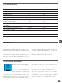
Parameter Scope Unit of change
Current time 00:00-23:59 1
Regeneration type/operation mode A-01, A-02, A-03, A-04 -
Regeneration start time 00:00-23:59 1
Number of days between regenerations 0-99 1
Time of back rinse 0 – 99 1
Time of brine draw and slow rinse 0 – 99 1
Time of water refill in water tank 0 – 99 1
Time of fast rinse 0 – 99 1
Type of external signal sent b-01, b-02 -

16
EN
9. CLEANING AND MAINTENANCE
9.1. CONTROLLING THE LEVEL OF SALT AND REFILLING THEREOF
The quantity of salt in the salt tank shall be checked regularly (recommended once per week), so that it
never runs out. Table 2 presents average salt consumption per regeneration. Salt shall be replenished as
the consumption thereof progresses, so that its level is always above water level. (Water shall not be visible).
Exclusively tablet salt intended for water softening shall be used.
ATTENTION! Salty water (brine) may cause eye, skin and wounds irritation. Do not
touch or otherwise contact it. In case of contact, wash brine with tap water.
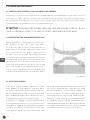
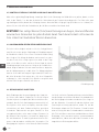
9.2. PREVENTING THE AGGLOMERATION OF SALT
High air humidity or a wrong type of salt may cause
the formation of large salt chunks (salt depos-
its) in the salt tank. The process may protrude the
preparation of the proper amount of brine and,
as a result, prevent the proper regeneration of
the device. As a result, water will not be softened.
In case of a suspicion that a salt deposit was formed,
one may knock on the walls of the salt tank or pour
hot water over the salt deposit to break it. A salt
chunk may also be broken into pieces with a long
object (e.g., a pipe). If salt agglomerated excessive-
ly as a result of bad quality thereof, the brine tank
shall be rinsed and fi lled with salt of proper quality.
Salt deposit
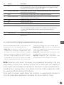
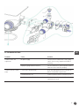
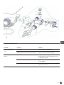
9.3. INJECTOR CLEANING
If the device is penetrated by impurities as sand,
small pebbles or other deposits, they may block
the injector (an element of the softener responsi-
ble for sucking brine). If the softener is protected
with a sedimentation pre-fi lter, whereas the salt is
of good quality, the injector should not clog.
If, however, it is clogged, it shall be cleaned. Fig. E
shows a diagram of the injector. The elements most
vulnerable to clogging are marked with numbers
12 and 14. In order to clean the injector, water inlet
to the device shall be shut off. Successively, cold
water tap shall be opened to release pressure from
the system. Mounting bolts shall be unscrewed
(the location thereof is marked with number 16)
with a screwdriver. The injector shall then be dis-
connected from the control head. Mind the seals.
Elements 12 and 14 may be unscrewed gently with
a screwdriver. All parts can be cleaned with water
and then blown through. After drying, they shall be
assembled again and the injector can be installed
in a manner reverse to the instructions above.

17
EN
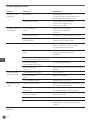
10. TROUBLESHOOTING
Problem Cause Solution
The device does not
regenerate
No power supply Check electrical connections - fuses, plug,
switch. If necessary, regenerate the device
manually
Improperly programmed controller Set the controller or contact a professional in
order to set the controller properly
The device delivers hard
water
Lack of salt in the brine tank Refill salt and regenerate the resin with the
button of immediate regeneration
Contaminated injector Contact a professional or clean the injector
Insufficient water refill of the brine tank Check the time of brine tank refill and
regenerate the resin

18
EN
Problem Cause Solution
Pressure drop Deposits of iron in the softener Clean the device and resin.
Increase the frequency of regeneration and /
or duration of the back rinse
Clogged water installation Check if impurities from water did not clog
the water installation upstream the device
Controller’s inlet contaminated with
impurities remaining from installation works
Remove impurities and clean the controller
Contaminated pre-cleaning filter cartridge Clean the cartridge or replace
Air in the system Check the installation and verify if brine is
present in the tank
Too much water in the
brine tank
Clogged injector Clean the injector
Foreign bodies in the brine valve Replace the brine valve
Power supply interrupted Check the electrical connections
The device does not suck
the brine
Too low pressure in the water mains Increase the pressure of water at the inlet to
the water treatment system, to the minimum
of 1.8 bar
Clogged brine supply hose to the controller Check the brine supply hose and remove any
impurities protruding the flow
Leak from the brine supply hose Replace the brine supply hose to the
controller
Damaged injector Replace the injector
Foreign bodies in the valve Check the inside of the valve, remove any
impurities, check the operation of valve in
different regeneration positions
Constant leak to sewage Power supply interrupted
during regeneration
Check the electrical connections

19
EN
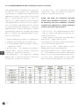
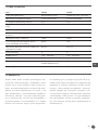
11. SPECIFICATION DATA
Code 230442 230459
Regeneration methods semi-automatically automatically (timing)
Dimensions [mm] 195x360x(H)x510 206x380x(H)480
Rated flow [m3/h] 0,3 0,3
Average consumption of salt per regeneration [kg] 0,5 0,5
Regeneration tany [kg] 8 8
Maximum water flow [l/min] 5 5
Effectiveness at 10°dH [l] 1200 1200
Protection against access of children - Automatic
keypad lock
None Yes
Ion exchanger tank’s dimensions [cale] Ø7x13 Ø7x13
Ion exchanger content [l] 4 4
Voltage [V]
100 - 240 VAC 100 - 240 VAC
Power [W] 18 18
Electric control panel None (only led indicators) Tak
Weight [kg] 8,0 7,7
12. WARRANTY
Any defect affecting the functionality of the ap-
pliance which becomes apparent within one year
after purchase will be repaired by free repair or re-
placement provided the appliance has been used
and maintained in accordance with the instruc-
tions and has not been abused or misused in any
way. Your statutory rights are not affected. If the
appliance is claimed under warranty, state where
and when it was purchased and include proof of
purchase (e.g. receipt). In line with our policy of
continuous product development we reserve the
right to change the product, packaging and docu-
mentation specifications without notice.
13. DISCARDING & ENVIRONMENT
When decommissioning the applian-
ce, the product must not be disposed
of with other household waste. In-
stead, it is your responsibility to
dispose to your waste equipment by
handing it over to a designated collection point. Failure
to follow this rule may be penalized in accordance with
applicable regulations on waste disposal. The separate
collection and recycling of your waste equipment at the
time of disposal will help conserve natural resources
and ensure that it is recycled in a manner that protects
human health and the environment. For more informa-
tion about where you can drop off your waste for recyc-
ling, please contact your local waste collection compa-
ny. The manufacturers and importers do not take
responsibility for recycling, treatment and ecological
disposal, either directly or through a public system.

20
EN
Strona się ładuje...
Strona się ładuje...
Strona się ładuje...
Strona się ładuje...
Strona się ładuje...
Strona się ładuje...
Strona się ładuje...
Strona się ładuje...
Strona się ładuje...
Strona się ładuje...
Strona się ładuje...
Strona się ładuje...
Strona się ładuje...
Strona się ładuje...
Strona się ładuje...
Strona się ładuje...
Strona się ładuje...
Strona się ładuje...
Strona się ładuje...
Strona się ładuje...
Strona się ładuje...
Strona się ładuje...
Strona się ładuje...
Strona się ładuje...
Strona się ładuje...
Strona się ładuje...
Strona się ładuje...
Strona się ładuje...
Strona się ładuje...
Strona się ładuje...
Strona się ładuje...
Strona się ładuje...
Strona się ładuje...
Strona się ładuje...
Strona się ładuje...
Strona się ładuje...
Strona się ładuje...
Strona się ładuje...
-
 1
1
-
 2
2
-
 3
3
-
 4
4
-
 5
5
-
 6
6
-
 7
7
-
 8
8
-
 9
9
-
 10
10
-
 11
11
-
 12
12
-
 13
13
-
 14
14
-
 15
15
-
 16
16
-
 17
17
-
 18
18
-
 19
19
-
 20
20
-
 21
21
-
 22
22
-
 23
23
-
 24
24
-
 25
25
-
 26
26
-
 27
27
-
 28
28
-
 29
29
-
 30
30
-
 31
31
-
 32
32
-
 33
33
-
 34
34
-
 35
35
-
 36
36
-
 37
37
-
 38
38
-
 39
39
-
 40
40
-
 41
41
-
 42
42
-
 43
43
-
 44
44
-
 45
45
-
 46
46
-
 47
47
-
 48
48
-
 49
49
-
 50
50
-
 51
51
-
 52
52
-
 53
53
-
 54
54
-
 55
55
-
 56
56
-
 57
57
-
 58
58


Hendi 299265 Instrukcja obsługi
- Typ
- Instrukcja obsługi
- Niniejsza instrukcja jest również odpowiednia dla
w innych językach
- Deutsch: Hendi 299265 Benutzerhandbuch
- English: Hendi 299265 User manual
Powiązane artykuły
Inne dokumenty
-
Pentair SIATA V132-SFE Instrukcja obsługi
-
EcoWater ESM9CE+ Instructions Manual
-
Bartscher 109901 Instrukcja obsługi
-
Electrolux ESF5542LOW Instrukcja obsługi
-
Electrolux ESF8635ROX Instrukcja obsługi
-
EcoWater Comfort series Instructions Manual
-
Samsung DW60A6082BB Instrukcja obsługi
-
-
 Kratki MSK Instrukcja obsługi
-
Kärcher ABS WSO SB-WASH Instrukcja obsługi
