AAT NVIP-6DN7000C-1P Instrukcja obsługi
- Kategoria
- Kamery ochrony
- Typ
- Instrukcja obsługi

U ser’s manual
( short )
NVIP-6DN7000C-1P

NVIP-6DN7000C-1P User’s manual (short form) ver.1.0
All rights reserved © AAT Holding S.A.
2
NVIP-6DN7000C-1P User’s manual (short form) ver.1.0
IMPORTANT SAFEGUARDS AND WARNINGS
EMC (2004/108/EC) and LVD (2006/95/EC ) Directives
CE Marking
Our products are manufactured to comply with requirements of the following directives and
national regulations implementing the directives:
Electromagnetic compatibility EMC 2004/108/EC.
Low voltage LVD 2006/95/EC with further amendment. The Directive applies to electrical
equipment designed for use with a voltage rating of between 50VAC and 1000VAC as well
as 75VDC and 1500VDC.
WEEE Directive 2012/19/UE
Information on Disposal for Users of Waste Electrical and Electronic Equipment
This appliance is marked according to the European 1000VAC Directive on Waste Electrical and
Electronic Equipment (2012/19/UE) and further amendments. By ensuring this product is
disposed of correctly, you will help to prevent potential negative consequences for the
environment and human health, which could otherwise be caused by inappropriate waste
handling of this product.
The symbol on the product, or the documents accompanying the product, indicates that this appliance
may not be treated as household waste. It shall be handed over to the applicable collection point for
used up electrical and electronic equipment for recycling purpose. For more information about
recycling of this product, please contact your local authorities, your household waste disposal service
or the shop where you purchased the product.
RoHS Directive 2011/65/UE
Out of concern for human health protection and friendly environment, we assure that our products
falling under RoHS Directive regulations, regarding the restriction of the use of hazardous
substances in electrical and electronic equipment, have been designed and manufactured in
compliance with the above mentioned regulations. Simultaneously, we claim that our
products have been tested and do not contain hazardous substances whose exceeding limits
could have negative impact on human health or natural environment
Information
The device, as a part of professional CCTV system used for surveillance and control, is not designed
for self installation in households by individuals without technical knowledge.
Excluding of responsibility in case of damaging data on a disk or other devices:
The manufacturer does not bear any responsibility in case of damaging or losing data on a disk or other
devices during device operation.
WARNING!
PRIOR TO UNDERTAKING ANY ACTION THAT IS NOT DESCRIBED FOR THE GIVEN
PRODUCT IN USER’S MANUAL AND OTHER DOCUMENTS DELIVERED WITH THE
PRODUCT, OR IF IT DOES NOT ARISE FROM THE USUAL APPLICATION OF THE
PRODUCT, MANUFACTURER MUST BE CONTACTED UNDER THE RIGOR OF EXCLUDING
THE MANUFACTURER’S RESPONSIBILITY FOR THE RESULTS OF SUCH AN ACTION.

NVIP-6DN7000C-1P User’s manual (short form) ver.1.0
All rights reserved © AAT Holding S.A.
3
NVIP-6DN7000C-1P User’s manual (short form) ver.1.0
IMPORTANT SAFEGUARDS AND WARNINGS
WARNING!
THE KNOWLEDGE OF THIS MANUAL IS AN INDESPENSIBLE CONDITION OF A PROPER
DEVICE OPERATION. YOU ARE KINDLY REQUSTED TO FAMILIRIZE YOURSELF WITH
THE MANUAL PRIOR TO INSTALLATION AND FURTHER DEVICE OPERATION.
WARNING!
USER IS NOT ALLOWED TO DISASSEMBLE THE CASING AS THERE ARE NO
USER-SERVICEABLE PARTS INSIDE THIS UNIT. ONLY AUTHORIZED SERVICE
PERSONNEL MAY OPEN THE UNIT
INSTALLATION AND SERVICING SHOULD ONLY BE DONE BY QUALIFIED SERVICE
PERSONNEL AND SHOULD CONFORM TO ALL LOCAL REGULATIONS
1. Prior to undertaking any action please consult the following manual and read all the safety and
operating instructions before starting the device.
2. Please keep this manual for the lifespan of the device in case referring to the contents of this manual
is necessary;
3. All the safety precautions referred to in this manual should be strictly followed, as they have a direct
influence on user’s safety and durability and reliability of the device;
4. All actions conducted by the servicemen and users must be accomplished in accordance with the
user’s manual;
5. The device should be disconnected from power sources during maintenance procedures;
6. Usage of additional devices and components neither provided nor recommended by the producer is
forbidden;
7. You are not allowed to use the camera in high humidity environment (i.e. close to swimming pools,
bath tubs, damp basements);
8. Mounting the device in places where proper ventilation cannot be provided (e. g. closed lockers etc.)
is not recommended since it may lead to heat build-up and damaging the device itself as a
consequence;
9. Mounting the camera on unstable surface or using not recommended mounts is forbidden.
Improperly mounted camera may cause a fatal accident or may be seriously damaged itself. The
camera must be mounted by qualified personnel with proper authorization, in accordance with this
user’s manual.
10. Device should be supplied only from a power sources whose parameters are in accordance with
those specified by the producer in the camera technical datasheet. Therefore, it is forbidden to
supply the camera from a power sources with unknown parameters, unstable or not meeting
producer’s requirements;
Due to the product being constantly enhanced and optimized, certain parameters and functions
described in the manual in question may change without further notice.
The most current version of this manual (short), and the full version of the manual can be found at
www.novuscctv.com/en

NVIP-6DN7000C-1P User’s manual (short form) ver.1.0
All rights reserved © AAT Holding S.A.
4
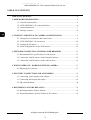
NVIP-6DN7000C-1P User’s manual (short form) ver.1.0
TABLE OF CONTENTS.................................................................................................4
1. FOREWORD INFORMATION..................................................................................5
1.1. General Characteristics.....................................................................................5
1.2. NVIP-6DN7000C-1P tech specification .........................................................6
1.3. Camera dimension ...........................................................................................7
1.4. Package contents..............................................................................................8
2. START-UP AND INITIAL IP CAMERA CONFIGURATION ................................9
2.1. Description of connectors and control tools ......................................................9
2.2. NVIP-6DN7000C-1P lens mount .................................................................10
2.3. Starting the IP camera ....................................................................................11
2.4. Initial configuration via the Web browser.......................................................12
3. NETWORK CONNECTION UTILIZING WEB BROSWER ...............................13
3.1. Recommended PC specification for web browser............................................13
3.2. Connection with IP camera via the Internet Explorer.......................................13
3.3. Connection with IP camera via the other browser............................................15
4. WWW INTERFACE - WORKING WITH IP CAMERA .......................................17
4.1. Displaying live pictures...................................................................................17
5. ELECTRIC CONNECTORS AND ACCESORIES ...............................................19
5.1. Connecting power supply to the camera. ........................................................19
5.1. Connecting alarm input and output..................................................................19
5.2. SD card installation ........................................................................................20
6. RESTORING FACTORY DEFAULTS ..................................................................21
6.1. Restoring software factory defaults .................................................................21
6.2. Restoring hardware factory defaults in IP cameras .........................................21
TABLE OF CONTENTS

NVIP-6DN7000C-1P User’s manual (short form) ver.1.0
All rights reserved © AAT Holding S.A.
5
NVIP-6DN7000C-1P User’s manual (short form) ver.1.0
1. FOREWORD INFORMATION
1.1. General Characteristics
Sensor resolution: 6.0 megapixels
Mechanical IR cut filter
IR operation capability
Min. Illumination from 0,0009 lx/F=1.2
Wide Dynamic Range (WDR) for enhanced image quality in diverse light conditions
Digital Slow Shutter (DSS)
Digital Noise Reduction (DNR)
Privacy zones: 5
1 Alarm input and 1 output
Compression: H.264, M-JPEG
Max video processing resolution: 3072 x 2048
Quadruple streaming: compression, resolution, speed and quality defined individually for each
video stream
RTP/RTSP protocol support for video transmission
Pre & post-alarm functions
Hardware motion detection
Built-in webserver: camera configuration through the website
MicroSD/SDHC/SDXC card support
Wide range of responses to alarm events: e-mail with attachment, saving file on FTP server,
triggering alarm output, saving file on SD/SDHC/SDXC card, HTTP notification
Network protocol support: HTTP, TCP/IP, IPv4/v6, UDP, HTTPS, Multicast, FTP, DHCP,
DDNS, NTP, RTSP, RTP, UPnP, SNMP, QoS
Software: NMS (NOVUS MANAGEMENT SYSTEM) for video recording, live monitoring,
playback and remote IP devices administration
Power supply: 12VDC, PoE (Power over Ethernet)
FOREWORD INFORMATION

NVIP-6DN7000C-1P User’s manual (short form) ver.1.0
All rights reserved © AAT Holding S.A.
6
NVIP-6DN7000C-1P User’s manual (short form) ver.1.0
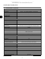
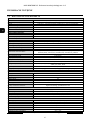
1.2. NVIP-6DN7000C-1P specification
FOREWORD INFORMATION
IMAGE
Image Sensor 6 MPX CMOS sensor 1/1.8” SONY Exmor R STARVIS
Number of Effective Pixels 3072 (H) x 2048 (V)
Min. Illumination 0.02 lx/F1.2 - color mode (DSS), 0.0009 lx/F1.2 - B/W mode (DSS)
Electronic Shutter auto/manual: 1/1 s ~ 1/10000 s
Digital Slow Shutter (DSS) up to 1 s
Wide Dynamic Range (WDR) yes
Digital Noise Reduction (DNR) 2D, 3D
COMPATIBLE LENSES
Mount Type CS
Iris Mode D
DAY/NIGHT
Switching Type mechanical IR cut filter
Switching Mode auto, manual, time, external, smart
Switching Level Adjustment yes
Switching Schedule yes
Visible Light Sensor yes
NETWORK
Stream Resolution
3072x2048, 1920x1080 (Full HD), 1280x1024 (SXGA), 1280x720 (HD), 1024x768 (XGA),
800x600 (SVGA), 720x576 (D1), 640x480 (VGA), 352x288 (CIF), 320x240
Frame Rate 30 fps for 3072x2048, 60 fps for 1920x1080 (Full HD) and lower resolutions
Multistreaming Mode 4 streams
Video/Audio Compression H.264, MJPEG/G.711, G.726, AAC, LPCM
Number of Simultaneous Connections max. 4
Bandwidth 45 Mb/s in total
Network Protocols Support
HTTP, TCP/IP, IPv4/v6, UDP, HTTPS, Multicast, FTP, DHCP, DDNS, NTP, RTSP, RTP, UPnP,
SNMP, QoS, PPPoE, SMTP
ONVIF Protocol Support Profile S (ONVIF 2.6)
Camera Configuration from Internet Explorer browser, languages: Polish, English, Russian, and others
Compatible Software NMS
OTHER FUNCTIONS
Privacy Zones 5
Motion Detection yes
Region of interest (ROI) 4
Audio Detection yes
Image Processing 90˚ image rotation, 180˚ image rotation, sharpening, mirror effect
Prealarm/Postalarm up to 3 s or 20 frames/up to 9999 s or 20 frames
System Reaction to Alarm Events
e-mail with attachment, saving file on FTP server, saving file on SD card, saving file on
NAS server, alarm output activation, HTTP notification
INTERFACES
Video Output BNC, 1.0 Vp-p, 75 Ohm - maintenance only
Audio Input/Output 1 x Jack (3.5 mm)/1 x Jack (3.5 mm)
Alarm Input/Output 1 (NO/NC)/1 relay type
Network Interface 1 x Ethernet - RJ-45 interface, 10/100/1000 Mbit/s
Memory Card Slot microSD
INSTALLATION PARAMETERS
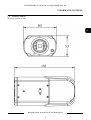
Dimensions (mm) 80 (W) x 53 (H) x 150 (L)
Weight 0.4 kg
Enclosure aluminium, white
Power Supply PoE, 12 VDC
Power Consumption 8.5 W
Operating Temperature -10°C ~ 50°C
Operating temperature with housing -40°C ~ 50°C

NVIP-6DN7000C-1P User’s manual (short form) ver.1.0
All rights reserved © AAT Holding S.A.
7
NVIP-6DN7000C-1P User’s manual (short form) ver.1.0
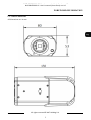
FOREWORD INFORMATION
1.3. Camera dimensions
All dimensions are in mm

NVIP-6DN7000C-1P User’s manual (short form) ver.1.0
All rights reserved © AAT Holding S.A.
8
NVIP-6DN7000C-1P User’s manual (short form) ver.1.0
1.4. Package contents
After you open the package make sure that the following elements are inside:
IP camera
230 VAC / 12 VDC power supply
Accessories bag
Short version of user’s manual
CD containing manual and software
If any of this elements has been damaged during transport, pack all the elements back into the original
box and contact your supplier for further assistance.
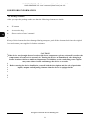
CAUTION!
If the device was brought from a location with lower temperature, please wait until it reaches the
temperature of location it is currently in. Turning the device on immediately after bringing it
from a location with lower ambient temperature is forbidden, as the condensing water vapour
may cause short-circuits and damage the device as a result.
Before starting the device familiarize yourself with the description and the role of particular
inputs, outputs and adjusting elements that the device is equipped with.
1.4. Package contents
After you open the package make sure that the following elements are inside:
IP camera
Accessories bag
Short version of user’s manual
If any of this elements has been damaged during transport, pack all the elements back into the original
box and contact your supplier for further assistance.
CAUTION!
If the device was brought from a location with lower temperature, please wait until it reaches the
temperature of location it is currently in. Turning the device on immediately after bringing it
from a location with lower ambient temperature is forbidden, as the condensing water vapour
may cause short-circuits and damage the device as a result.
Before starting the device familiarize yourself with the description and the role of particular
inputs, outputs and adjusting elements that the device is equipped with.
FOREWORD INFORMATION

NVIP-6DN7000C-1P User’s manual (short form) ver.1.0
All rights reserved © AAT Holding S.A.
9
NVIP-6DN7000C-1P User’s manual (short form) ver.1.0
2. START-UP AND INITIAL IP CAMERA CONFIGURATION
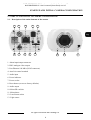
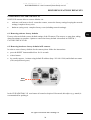
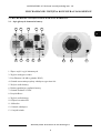
2.1. Description of the main elements of the camera
1. Alarm input/output connector
2. BNC analogue video output
3. Port Ethernet 100 Mb/s (RJ-45 connector)
4. Auto Iris control terminal
5. Audio input
6. Power indicator
7. Power socket
8. Reset button (reverts to factory defaults)
9. Audio output
10. MicroSD card slot
11. Microphone
12. Lens mount socket
13. Light sensor
START-UP AND INITIAL CAMERA CONFIGURATION
1 2 3 4 5
7 8 6 9
10
11 13 12

NVIP-6DN7000C-1P User’s manual (short form) ver.1.0
All rights reserved © AAT Holding S.A.
10
NVIP-6DN7000C-1P User’s manual (short form) ver.1.0
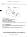
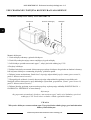
2.2. NVIP-6DN7000C-1P lens mount
Lens Mount:
1. Remove the protecting cap.
2. Remove the sensor protective foil located under the cap
3. Attach the C/CS lens adapter if necessary.
4. Attach the lens to the camera by turning it clockwise.
5. Connect the lens plug to the auto iris connector on the side of the camera. If you are using a lens with
manual iris - skip this step.
6. Reset the mechanism of "Back focus" using the appropriate option in the camera menu (see page 18,
position 5. Focusing function buttons)
7. Adjust the area of view and sharpness of the image using the appropriate controls on the lens. Then
you can use the precise sharpening option, pressing the "PushAF" button (see page 18, position 5.
Focusing function buttons)
8. Complete the correction of drive level of the lens iris using the option SYSTEM -> IRIS
ADJUSTMENT in the camera menu.
Information:
To mount C type lens you should use additional C/CS adapter (not included)
Warning
Use lens with a C-mount without the appropriate adapter ring may cause damage the camera
and /or lens.
START-UP AND INITIAL CAMERA CONFIGURATION
IP camera C/CS lens adapter Lens

NVIP-6DN7000C-1P User’s manual (short form) ver.1.0
All rights reserved © AAT Holding S.A.
11
NVIP-6DN7000C-1P User’s manual (short form) ver.1.0
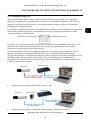
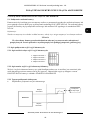
2.3. Starting the IP camera
To run NOVUS IP camera you have to connect ethernet cable between camera and network switch
with PoE support (IEEE 802.3af).
You can also power it directly via power supply adapter with parameters compatible with camera
power supply specification.
After connecting power supply power indicator (green LED) should light on, also the green LED on the
RJ45 connector, indicating a successful connection to a network switch, will be lit. If the connection is
successfully established, orange LED blinks with a frequency proportional to the quantity of data flow.
Initialization process takes about 30 seconds. You can then proceed to connect to the camera via web
browser. If connection isn’t established (the network cable is disconnected) green and orange LEDs
aren't active, solid orange light means that network connection is ok but camera doesn't receive or send
any data, with possible PC network settings error.
The recommended way to start an IP camera and perform its configuration is a connection directly to
the network switch which is not connected to other devices. To obtain further information about
network configuration parameters (IP address, gateway, network mask, etc.) please contact your
network administrator.
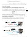
Connection utilising network switch with PoE support
Connection utilising external power supply and network switch
START-UP AND INITIAL CAMERA CONFIGURATION
Computer IP camera
Power supply and data
transmission
Data transmission
PoE Network switch
IP camera
Data transmission
Data transmission
Network switch
Computer
Power supply
Orange LED Green LED

NVIP-6DN7000C-1P User’s manual (short form) ver.1.0
All rights reserved © AAT Holding S.A.
12
NVIP-6DN7000C-1P User’s manual (short form) ver.1.0
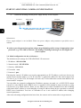
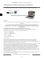
Connection utilising external power supply directly to the computer
Information:
Power supply adapter is not included. Please use power adapter with parameters specified in user‘s
manual.
Caution:
In order to provide protection against voltage surges/lightning strikes, usage of appropriate surge
protectors (e.g. NVS-110E) is advised. Any damages resulting from surges are not eligible for
service repairs.
2.4. Initial configuration via the web browser
The default network settings for NVIP-6DN7000C-1P camera are:
1. IP address - 192.168.1.200
2. Network mask - 255.255.255.0
3. Gateway - 192.168.1.1
4. User name - root
5. Password - pass
Knowing the camera’s IP address you need to appropriately set PC IP address, so the two devices can
operate in one network subnet ( e.g. for IP 192.168.1.1, appropriate address for the camera ranges from
192.168.1.2 to 192.168.1.254, for example 192.168.1.60). It is not allowed to set the same addresses for
camera and PC computer
You can either set a network configuration (IP address, gateway, net mask, etc.) of NOVUS IP camera
yourself or select DHCP mode (DHCP server is required in this method in target network) by using
web browser or by NMS software. When you use DHCP server check IP address lease and its linking
with camera MAC address to avoid changing or losing IP address during device operation or network/
DHCP server breakdown. You have to remember to use a new camera IP address after changing
network parameters.
After network setting configuration has been done, the camera can be connected to a target network.
START-UP AND INITIAL CAMERA CONFIGURATION
IP camera
Data transmission - cross over cable
Computer
Power supply

NVIP-6DN7000C-1P User’s manual (short form) ver.1.0
All rights reserved © AAT Holding S.A.
13
NVIP-6DN7000C-1P User’s manual (short form) ver.1.0
3. NETWORK CONNECTION UTILIZING WEB BROSWER
3.1. Recommended PC specification for web browser connections
Requirements below apply to connection with an IP camera, assuming smooth image display in
3072x2048 for 30 fps.
1. CPU Intel Core i3 3 GHz or newer
2. RAM memory min. 4 GB
3. VGA card NVidia GeForce with 512 MB of RAM memory, or equivalent
4. OS Windows 7 / 8 / 8.1 / 10
5. Network card 100/1000 Mb/s
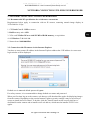
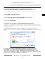
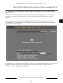
3.2. Connection with IP camera via the Internet Explorer
You have to enter camera IP address in the Internet Explorer address bar. If IP address is correct user
login window will be displayed:
Default user is root and default password is pass.
For safety reasons, it is recommended to change default user name and password.
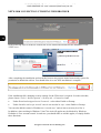
When you first time log on to the camera, web browser will download the applet for displaying images
from the camera. Depending on the current Internet Explorer security settings it may be necessary to
accept an install ActiveX control. To do this, click the "Install" button on the security info bar, to
download from the camera and to install install.cab add-on, which runs the installer NVIP Viewer
applet.
NETWORK CONNECTION UTILIZING WEB BROWSER

NVIP-6DN7000C-1P User’s manual (short form) ver.1.0
All rights reserved © AAT Holding S.A.
14
NVIP-6DN7000C-1P User’s manual (short form) ver.1.0
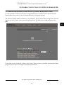
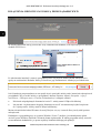
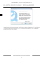
In the following steps is needed to confirm the will to install add-on and start the installation of the
NVIPViewer:
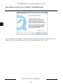
After completing the installation and restart the browser may appear monit from security system for
permission to launch the add-on. You should allow it to run. Now installation is complete:
If the installation fails, changing security settings for the IE browser is required. In order to do that,
please choose: Tools > Internet options > Security tab > Custom level and:
Under Download unsigned ActiveX controls - select either Enable or Prompt
Under Initialize and script ActiveX controls not marked as safe - select Enable or Prompt
You can also add the camera’s IP address to “trusted zone” and set lowest security level for it.
In addition, when working in Windows Vista/7 the ActiveX applet may be blocked by Windows
Defender or User account control. In such case you should allow to run this applet, or simply disable
these functions.
NETWORK CONNECTION UTILIZING WEB BROWSER

NVIP-6DN7000C-1P User’s manual (short form) ver.1.0
All rights reserved © AAT Holding S.A.
15
NVIP-6DN7000C-1P User’s manual (short form) ver.1.0
3.3. Connection with IP camera via other browser eg. Chrome, Mozilla Firefox, Safari )
It is also possible to connect to the camera using Mozilla Firefox, but this browser doesn't offer full
functionality of the camera, so the recommended browser is Internet Explorer.
The first run of the IP camera in browser is very similar to the IE version. After you type the correct IP
address you have to write correct username and password. The default user is root and password is
pass.
Next, blank screen is displayed, without video stream. Then you have to install the missing Quick Time
plug-in from site: http://www.apple.com/quicktime/download/
NETWORK CONNECTION UTILIZING WEB BROWSER

NVIP-6DN7000C-1P User’s manual (short form) ver.1.0
All rights reserved © AAT Holding S.A.
16
NVIP-6DN7000C-1P User’s manual (short form) ver.1.0
After downloading and running it, a window depicting installation of particular components is then
displayed. After proper installation pictures from the camera should become visible
NETWORK CONNECTION UTILIZING WEB BROWSER

NVIP-6DN7000C-1P User’s manual (short form) ver.1.0
All rights reserved © AAT Holding S.A.
17
NVIP-6DN7000C-1P User’s manual (short form) ver.1.0
4. WWW INTERFACE - WORKING WITH IP CAMERA
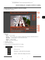
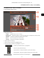
4.1. Displaying live pictures
1. Main tabs
Home — live view page
System — camera settings (IP, recording, sending alarm messages, motion detection etc.)
Streaming — stream settings for video and audio streams
Camera — picture settings
Logout - log off the current user
2. Language selection.
3. Video format selection.
4. Settings and functions buttons while "live" viewing:
- Video size in web browser
- Full screen view
- Microphone - enable audio from microphone
- Speaker - enable audio sending to the camera
WWW INTERFACE - WORKING WITH IP CAMERA
1.
2.
3.
4.
5.
6.

NVIP-6DN7000C-1P User’s manual (short form) ver.1.0
All rights reserved © AAT Holding S.A.
18
NVIP-6DN7000C-1P User’s manual (short form) ver.1.0
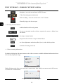
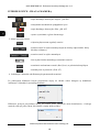
5. Focusing function buttons:
6. Video streaming information.
By double-clicking the left mouse button on the video screen are available additional information about
the currently displayed image:
Right-clicking on the video screen activate a context menu from which you can turn on the full screen,
or set the size of video buffer:
WWW INTERFACE - WORKING WITH IP CAMERA
- Snapshot - saves the current frame in JPEG format
- Video Streaming pause/play button
- Web recording - saves the current video in AVI format
- Manually trigger the alarm output
- enables/disables the focusing menu
- focuses on automatic mode on objects, respectively: nearer or farther from
the camera
- focusing in manual mode
- drop-down list to choose a step for manual focus
- set focus adjustment mechanism (Back focus) in the default position
- automatic focusing (Push AF)

NVIP-6DN7000C-1P User’s manual (short form) ver.1.0
All rights reserved © AAT Holding S.A.
19
NVIP-6DN7000C-1P User’s manual (short form) ver.1.0
5. ELECTRIC CONNECTORS AND ACCESORIES
5.1. Connecting power supply to the camera.
The camera can be supplied by using RJ45 network socket or external power supply. To run IP camera
you have to connect ethernet cable between camera and network switch with PoE support (IEEE
802.3af). You can also use a power injector compatible with IEEE 802.3af standard.
Information:
Power supply adaptor is not included. Please use power adapter with parameters specified in user’s
manual.
Warning
In order to provide protection against voltage surges/lightning strikes, usage of appropriate surge
protectors is advised. Any damages resulting from surges are not eligible for service repairs.
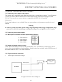
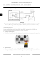
5.2. Connecting alarm inputs/outputs.
5.2.1 Description of terminals of alarm input/output connector:
5.2.2 Input and output connector states:
Alarm inputs and outputs cameras are fully customizable, ie. it is possible to set as the active state of
both: a short circuit condition or break condition. Suitable options are available in the SYSTEM menu of
the camera in the EVENTS -> APPLICATION tab.
5.2.3 Typical electrical connections
Alarm input connections example
ELECTRIC CONNECTORS AND ACCESORIES
1 - Alarm output +
2 - Alarm output -
3 - Alarm intput +
4 - Alarm intput -
Alarm intput -
IP Camera
Alarm intput +
Switch or sensor
contact

NVIP-6DN7000C-1P User’s manual (short form) ver.1.0
All rights reserved © AAT Holding S.A.
20
NVIP-6DN7000C-1P User’s manual (short form) ver.1.0
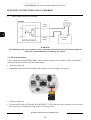
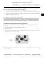
Alarm output connections example
WARNING
Not following to the correct polarity when connecting external devices to the alarm output can
cause the system malfunction or damage the camera.
5.3. SD card installation
Camera supports microSD/SDHC/SDXC cards with their capacity up to 64GB. In order to install the
card properly, please follow the instructions below:
Turn the camera off
Mount SD card in the socket located at the camera’s rear, according to the picture:
Turn the camera on
Format the SD card in STORAGE MANAGEMENT -> SD CARD tab. In the same tab, you can verify
the correctness of installation of the card by verifying its size.
ELECTRIC CONNECTORS AND ACCESORIES
IP Camera
Alarm
output +
Siren power
supply
Siren
Alarm output SSR relay
Alarm
output -
+ -
Strona się ładuje...
Strona się ładuje...
Strona się ładuje...
Strona się ładuje...
Strona się ładuje...
Strona się ładuje...
Strona się ładuje...
Strona się ładuje...
Strona się ładuje...
Strona się ładuje...
Strona się ładuje...
Strona się ładuje...
Strona się ładuje...
Strona się ładuje...
Strona się ładuje...
Strona się ładuje...
Strona się ładuje...
Strona się ładuje...
Strona się ładuje...
Strona się ładuje...
Strona się ładuje...
Strona się ładuje...
Strona się ładuje...
Strona się ładuje...
-
 1
1
-
 2
2
-
 3
3
-
 4
4
-
 5
5
-
 6
6
-
 7
7
-
 8
8
-
 9
9
-
 10
10
-
 11
11
-
 12
12
-
 13
13
-
 14
14
-
 15
15
-
 16
16
-
 17
17
-
 18
18
-
 19
19
-
 20
20
-
 21
21
-
 22
22
-
 23
23
-
 24
24
-
 25
25
-
 26
26
-
 27
27
-
 28
28
-
 29
29
-
 30
30
-
 31
31
-
 32
32
-
 33
33
-
 34
34
-
 35
35
-
 36
36
-
 37
37
-
 38
38
-
 39
39
-
 40
40
-
 41
41
-
 42
42
-
 43
43
-
 44
44


AAT NVIP-6DN7000C-1P Instrukcja obsługi
- Kategoria
- Kamery ochrony
- Typ
- Instrukcja obsługi
w innych językach
- English: AAT NVIP-6DN7000C-1P User manual
Powiązane artykuły
-
Novus NVIP-6DN3618V/IR-1P Instrukcja obsługi
-
-
-
-
-
-
-
-
-