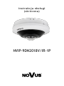
AAT NVIP-9DN2018V/IR-1P Instrukcja obsługi
- Kategoria
- Kamery ochrony
- Typ
- Instrukcja obsługi

User’s ma n ua l
(s h o rt form )
NVIP-9DN2018V/IR-1P

NVIP-9DN2018V/IR-1P - User’s manual (short) ver 1.1
All rights reserved © AAT Holding S.A.
2
IMPORTANT SAFEGUARDS AND WARNINGS
INFORMATION
EMC (2014/30/UE) and LVD (2014/35/UE) Directives
CE Marking
Our products are manufactured to comply with the requirements of the following directives and
national regulations implementing the directives:
- Electromagnetic compatibility EMC 2014/30/UE.
- Low voltage LVD 2014/35/EC with further amendment. The Directive applies to electrical
equipment designed for use with a voltage rating of between 50VAC and 1000VAC as well as
75VDC and 1500VDC.
WEEE Directive 2012/19/UE
Information on Disposal for Users of Waste Electrical and Electronic Equipment
This appliance is marked according to the European Directive on Waste Electrical and
Electronic Equipment (2012/19/UE) and further amendments. By ensuring this product is
disposed of correctly, you will help to prevent potential negative consequences for the
environment and human health, which could otherwise be caused by inappropriate waste
handling of this product.
The symbol on the product, or the documents accompanying the product, indicates that this appliance may
not be treated as household waste. It shall be handed over to the applicable collection point for used up
electrical and electronic equipment for recycling purpose. For more information about recycling of this
product, please contact your local authorities, your household waste disposal service or the shop where you
purchased the product.
RoHS Directive 2011/65/UE
Information concerning the restriction of use of hazardous substances in electrical electronic
equipment.
Out of concern for human health protection and friendly environment, we assure that our
products falling under RoHS Directive regulations, regarding the restriction of the use of
hazardous substances in electrical and electronic equipment, have been designed and
manufactured in compliance with the above mentioned regulations. Simultaneously, we
claim that our products have been tested and do not contain hazardous substances whose
exceeding limits could have negative impact on human health or natural environment.
Information
The device, as a part of professional CCTV system used for surveillance and control, is not designed for self
installation in households by individuals without technical knowledge.
Excluding of responsibility in case of damaging data on a disk or other devices:
The manufacturer does not bear any responsibility in case of damaging or losing data on a disk or other
devices during device operation.
WARNING!
PRIOR TO UNDERTAKING ANY ACTION THAT IS NOT DESCRIBED FOR THE GIVEN PRODUCT
IN USER’S MANUAL AND OTHER DOCUMENTS DELIVERED WITH THE PRODUCT, OR IF IT
DOES NOT ARISE FROM THE USUAL APPLICATION OF THE PRODUCT, MANUFACTURER
MUST BE CONTACTED UNDER THE RIGOR OF EXCLUDING THE MANUFACTURER’S
RESPONSIBILITY FOR THE RESULTS OF SUCH AN ACTION.

NVIP-9DN2018V/IR-1P - User’s manual (short) ver 1.1
All rights reserved © AAT Holding S.A.
3
IMPORTANT SAFEGUARDS AND WARNINGS
WARNING!
THE KNOWLEDGE OF THIS MANUAL IS AN INDESPENSIBLE CONDITION OF A PROPER DEVICE
OPERATION. YOU ARE KINDLY REQUSTED TO FAMILIRIZE YOURSELF WITH THE MANUAL
PRIOR TO INSTALLATION AND FURTHER DEVICE OPERATION.
WARNING!
USER IS NOT ALLOWED TO DISASSEMBLE THE CASING AS THERE ARE NO USER-
SERVICEABLE PARTS INSIDE THIS UNIT. ONLY AUTHORIZED SERVICE PERSONNEL MAY OPEN
THE UNIT.
INSTALLATION AND SERVICING SHOULD ONLY BE DONE BY QUALIFIED SERVICE PERSONNEL
AND SHOULD CONFORM TO ALL LOCAL REGULATIONS.
IMPORTANT SAFEGUARDS AND WARNINGS
1. Prior to undertaking any action please consult the following manual and read all the safety and operating
instructions before starting the device.
2. Please keep this manual for the lifespan of the device in case referring to the contents of this manual is
necessary;
3. All the safety precautions referred to in this manual should be strictly followed, as they have a direct
influence on user’s safety and durability and reliability of the device;
4. All actions conducted by the servicemen and users must be accomplished in accordance with the user’s
manual;
5. The device should be disconnected from power sources during maintenance procedures;
6. Usage of additional devices and components neither provided nor recommended by the producer is forbidden;
7. Mounting the device in places where proper ventilation cannot be provided (e. g. closed lockers etc.) is not
recommended since it may lead to heat build-up and damaging the device itself as a consequence;
8. Mounting the camera on unstable surface or using not recommended mounts is forbidden. Improperly
mounted camera may cause a fatal accident or may be seriously damaged itself. The camera must be mounted
by qualified personnel with proper authorization, in accordance with this user’s manual.
9. Device should be supplied only from a power sources whose parameters are in accordance with those
specified by the producer in the camera technical datasheet. Therefore, it is forbidden to supply the camera
from a power sources with unknown parameters, unstable or not meeting producer’s requirements;
10. Signal cables (conducting TV or / and telemetric signal) should be placed in a way excluding the possibility
of damaging them by accident. Special attention must be paid to cables getting from the camera and
connecting the power supply;
11. To avoid equipment damage, whole TV circuit should be equipped with properly made discharge-, overload-
and lightning protection devices. Usage of separating transformers is advised;
12. Electric installation supplying the device should be designed to meet the specifications given by the producer
in such a way that overloading is impossible;
13. User cannot repair or upgrade the equipment himself. All maintenance actions and repairs should be
conducted only by qualified service personnel;
14. Unplug the camera from the power source immediately and contact the proper maintenance department
when the following occurs:
• Damages to the power cord or to the plug itself;
• Liquids getting inside the device or exposure to strong mechanical shock;
• Device behaves in a way not described in the manual and all adjustments approved by the
manufacturer and possible to apply by user himself, seem not to have any effect;
• Camera or its casing is damaged;
• Atypical behaviour of the camera components can be seen (heard).
15. In necessity of repairs attention to using only original replacement parts (with their parameters in
accordance with those specified by the producer) should be paid. Non-licensed service and non-genuine
replacement parts may cause fire or electrocution.

NVIP-9DN2018V/IR-1P - User’s manual (short) ver 1.1
All rights reserved © AAT Holding S.A.
4
TABLE OF CONTENTS ..................................................................................................... 4
1. FOREWORD INFORMATION ................................................................................... ..5
1.1. General characteristics ......................................................................................... 5
1.2. Technical specification .................................................................................... ...6
1.3. Camera dimension ........................................................................................... ...7
1.4. Package contents ............................................................................................... ...7
2. START-UP AND INITIAL IP CAMERA CONFIGURATION ................................. 8
2.1. Description of connectors .................................................................................... 8
2.2. Power supply connection ..................................................................................... 9
2.3. Connecting ethernet cable ................................................................................... 9
2.4. Camera mounting .............................................................................................. 10
2.5. Starting the camera ............................................................................................ 11
2.6. Initial configuration via web browser ................................................................ 12
2.7. Security recommendations for network architecture and configuration............ 13
3. NETWORK CONNECTION UTILIZING WEB BROSWER ................................ 14
3.1. Recommended PC specification for web browser ............................................. 14
3.2. Connection with IP camera via web browser ..................................................... 14
4. USING AND CONFIGURING ..................................................................................... 16
4.1. Remote Preview Interface. ................................................................................. 16
5. ELECTRIC CONNECTORS ...................................................................................... 18
5.1. Connecting of the alarm input. ........................................................................... 18
5.2. Connecting of the alarm output .......................................................................... 18
6. RESTORING FACTORY DEFAULTS ..................................................................... 18
6.1. Software factory reset ......................................................................................... 18
6.1. Hardware factory reset ...................................................................................... 18
7. INSTALLING SD CARD ............................................................................................ 19
TABLE OF CONTENTS

NVIP-9DN2018V/IR-1P - User’s manual (short) ver 1.1
All rights reserved © AAT Holding S.A.
5
1. FOREWORD INFORMATION
1.1. General Characteristics
• Sensor resolution: 12 megapixels
• Mechanical IR cut filter, IR operation capability
• Min. Illumination from 0 lx with IR LED on
• Wide Dynamic Range (WDR) for enhanced image quality in diverse light conditions
• Digital Noise Reduction (DNR)
• Lens with remote focal and focus control, f=2.0/F=2.4
• Built-in LED illuminator: 3 pcs LED
• Compression of video stream: H.264/H265
• Max video processing resolution: 3000x3000
• Multi streaming: three independently configurable streams
• Stream parameters: compression, resolution, speed and quality defined individually for each
video stream
• RTP/RTSP protocol support for video transmission
• Two-way audio transmission
• Compression of audio stream: G.711, G.726, ADPCM
• Alarm input and output
• Hardware motion detection
• Hardware sabotage detection (lens shade)
• Built-in webserver: camera configuration through the website
• Wide range of responses to alarm events: e-mail with attachment, saving file on FTP server,
activation of alarm output, recording on SD card
• Four privacy zones
• Eight definable Region of Interest
• Power supply: 12VDC, PoE (Power over Ethernet 802.3af)
As the product is constantly improved and optimized, some of the parameters and functions described
in the attached manual may have changed.
Please read the latest short form user manual found at www.novuscctv.com/en
The website www.novuscctv.com/en also contains the full version of the user manual.
Information!
The manufacturer reserves the right to printing errors and technical specifications changes
without prior notice.
FOREWORD INFORMATION

NVIP-9DN2018V/IR-1P - User’s manual (short) ver 1.1
All rights reserved © AAT Holding S.A.
6
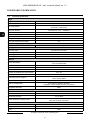
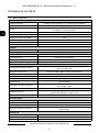
1.2. Technical specification
FOREWORD INFORMATION
Image
Image Sensor 12 MPX CMOS sensor 1/1.7” SONY Exmor R STARVIS
Number of Eecve Pixels 4072 (H) x 3046 (V)
Min. Illuminaon
0.04 lx/F2.4 - color mode,
0 lx (IR on) - B/W mode
Electronic Shuer auto/manual: 1/5 s ~ 1/20000 s
Digital Slow Shuer (DSS) up to 1/5 s
Wide Dynamic Range (WDR) yes
Digital Noise Reducon (DNR) 2D, 3D
Defog Funcon (F-DNR) yes
Back Light Compensaon (BLC) yes
Lens
Lens Type sheye, f=2.0 mm/F2.4
Day/Night
Switching Type mechanical IR cut lter
Switching Mode auto, manual
Switching Delay 1 ~ 36 s
Visible Light Sensor yes
Network
Stream Resoluon
3000 x 3000, 2560 x 2560, 2160 x 2160, 1520 x 1520, 1080 x 1080,
720 x 720, 480 x 480
Frame Rate 30 fps for 3000 x 3000 and lower resoluons
Mulstreaming Mode 3 streams
Video/Audio Compression H.264, H.265/G.711, G.726, ADPCM
Number of Simultaneous Connecons max. 10
Bandwidth 40 Mb/s in total
Network Protocols Support
HTTP, TCP/IP, IPv4, HTTPS, FTP, DHCP, DNS, DDNS, NTP, RTSP, RTP,
UPnP, PPPoE, SMTP
ONVIF Protocol Support Prole S
Camera Conguraon
from Internet Explorer browser
languages: Polish, English, Russian, and others
Compable Soware NMS
Other funcons
Privacy Zones 4
Moon Detecon yes
Prealarm/Postalarm -/up to 300 s
System Reacon to Alarm Events
e-mail with aachment, saving le on FTP server, saving le on SD
card, alarm output acvaon
IR LED
LED Number 3
Range 10 m
Angle 120°

NVIP-9DN2018V/IR-1P - User’s manual (short) ver 1.1
All rights reserved © AAT Holding S.A.
7
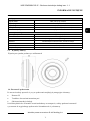
FOREWORD INFORMATION
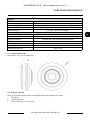
1.3. Camera dimensions
Dimensions are given in millimeters
1.4. Package contents
After you open the package make sure that the following elements are inside:
• IP camera
• Accessories bag
• Short version of user’s manual
Interfaces
Video Output BNC, 1.0 Vp-p, 75 Ohm
Audio Input/Output built-in microphone/-
Alarm Input/Output 1 (NO/NC)/1
Network Interface 1 x Ethernet - RJ-45 interface, 10/100 Mbit/s
Memory Card Slot microSD - capacity up to 128GB
Installaon parameters
Dimensions (mm) 120 (Ф) x 55 (H)
Weight 0.45 kg
Degree of Protecon IP 66 (details in the user’s manual on page 10)
Enclosure vandalproof aluminium, white
Power Supply PoE, 12 VDC
Power Consumpon 7 W, 11 W (IR on)
Operang Temperature -30°C ~ 55°C

NVIP-9DN2018V/IR-1P - User’s manual (short) ver 1.1
All rights reserved © AAT Holding S.A.
8
CAUTION!
If the device was brought from a location with lower temperature, please wait until it reaches the
temperature of location it is currently in. Turning the device on immediately after bringing it
from a location with lower ambient temperature is forbidden, as the condensing water vapour
may cause short-circuits and damage the device as a result.
Before starting the device familiarize yourself with the description and the role of particular
inputs, outputs and adjusting elements that the device is equipped with.
2. START-UP AND INITIAL CAMERA CONFIGURATION
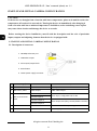
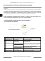
2.1. Description of connectors
START-UP AND INITIAL CAMERA CONFIGURATION
Nr Connector Type/Color Funcon Descripon
1 RJ45 socket, white Port Ethernet 100Mbps Ethernet connector
2
BNC socket, white Video output CVBS video output
3
ARK screw terminal
block
1. Alarm input A
Alarm input, congurable: NC or NO
2. Alarm input B
3. Alarm output A
Alarm output, NO (relay, 12VDC/24VAC 0.3A max)
4. Alarm output B
4 - RESET buon Buon to restore factory sengs
5 DC2,5/5,5 socket Power connector Power supply, 12VDC ± 10%
1. 100 Mbps Ethernet port
2. CVBS video output
3. Alarm input/output block
4. Reset buon
5. 12VDC power supply connector

NVIP-9DN2018V/IR-1P - User’s manual (short) ver 1.1
All rights reserved © AAT Holding S.A.
9
START-UP AND INITIAL IP CAMERA CONFIGURATION
2.2. Power supply connection
When powering the camcorder from an external 12VDC power supply, make sure it has the correct
settings and that the power supply connector has the correct polarity. Using an incorrect power supply
may result in malfunction or damage.
The camera can also be powered via an RJ45 network connector, using PoE (IEEE 802.3af)
technology. Please, use a network switch or an IEEE 802.3af compliant PoE power supply to power
the camera through the PoE.
CAUTION!
It is forbidden to use – as the camera power source – PoE equipment (adapters, etc.) not compatible with
IEEE 802.3af standard (items called “passive PoE power supply”). Damages that results from the usage
of improper power supply source are not covered by the warranty.
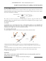
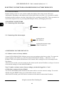
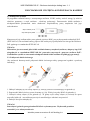
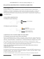
2.3. Connecting ethernet cable
To maintain tightness of ethernet cable connection, please follow instruction below:
1. Unscrew the nut (b) from the connector cover (a), mount the sealing ring on the socket (c)
2. Route the network cable through the components (a) and (b). Plug the RJ-45 connector into the
socket (c)
3. Screw the connector cover (a) on the socket (c). Inside the upper part of the connector cover (a)
push in to the stop the seal of the cable (d) - the seal is cut to insert on the network cable.
4. Tighten up to the stop nut (b)
WARNING!
Other connectors and sockets, outside of the RJ-45 socket, are not hermetically sealed. User
should seal this connector by himself.
b a
b
a
c
d
Center pin +12V
GND

NVIP-9DN2018V/IR-1P - User’s manual (short) ver 1.1
All rights reserved © AAT Holding S.A.
10
START-UP AND INITIAL IP CAMERA CONFIGURATION
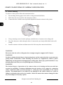
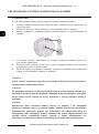
2.4. Camera mounting
To mount a camera please follow the instructions below:
Put mounting drawing paper to the wall or ceiling and mark drill holes.
Drill holes for screws and for video and power cables.
Connect the base with the camera position adjustment element as shown in the picture
Using mounting screws from the package, attach the base of camera to the ceiling/wall
Put video and power cables through a base of camera and a previously drilled hole in the wall/
ceiling.
Push the camera to the base and then turn to the left to snap the camera into the base
WARNING!
Please note that the wall or ceiling must have enough strength to support the IP Camera.
WARNING!
In order to obtain declared degree of protection please seal the camera bracket to prevent water
getting inside. Furthermore, when installing the bracket on rough/uneven surfaces, please
additionally seal the junction with appropriate sealing mass. Please pay special attention to any
mounting holes and if they are a loop-through ones, seal them too.
WARNING!
The declared degree of protection of the camera relates to its housing and does not take into
account the possibility of moisture infiltration into the interior of the camera by connecting
cables. Connection cables protection through i.e. sealing up is the responsibility of the camera
installer. The manufacturer is not liable for any damages to the camera caused as a result of
failing in performing that activity by installer, which also means that camera damaged in that
way is not subject to warranty repairs.

NVIP-9DN2018V/IR-1P - User’s manual (short) ver 1.1
All rights reserved © AAT Holding S.A.
11
START-UP AND INITIAL CAMERA CONFIGURATION
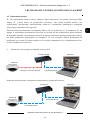
2.5. Starting the IP camera
To run NOVUS IP camera you have to connect ethernet cable between camera and network switch.
To power it up you can connect it directly via power supply adapter with parameters compatible with
camera power supply specification, or camera can be powered with PoE (IEEE 802.3af ) compatible
switch.
After connecting power supply it takes about 30 seconds to start camera. Then You can proceed to
connect to the camera via web browser.
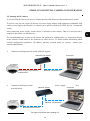
The recommended way to start an IP camera and perform its configuration is a connection directly
to the network switch which is not connected to other devices. To obtain further information about
network configuration parameters (IP address, gateway, network mask, etc.) please contact your
network administrator.
• Connection utilising network switch with PoE support
• Connection utilising external
power supply and
network switch
Network transmission
Network transmission
Network switch
Computer
IP camera
Computer
IP camera
Power supply and network
transmission
Network transmission
Network PoE switch

NVIP-9DN2018V/IR-1P - User’s manual (short) ver 1.1
All rights reserved © AAT Holding S.A.
12
START-UP AND INITIAL CAMERA CONFIGURATION
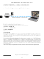
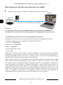
• Connection utilising external power supply directly to the computer
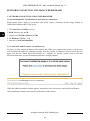
2.6. Initial configuration via the web browser
The default network settings for NVIP-9DN2018V/IR-1P camera are:
1. IP address= 192.168.1.200
2. Network mask - 255.255.255.0
3. Gateway - 192.168.1.1
4. User name - root
5. Password - pass
Knowing the camera’s IP address you need to appropriately set PC IP address, so the two devices can
operate in one network subnet ( e.g. for IP 192.168.1.1, appropriate address for the camera ranges from
192.168.1.2 to 192.168.1.254, for example 192.168.1.60). It is not allowed to set the same addresses for
camera and PC computer
You can either set a network configuration (IP address, gateway, net mask, etc.) of NOVUS IP camera
yourself or select DHCP mode (DHCP server is required in this method in target network) by using
web browser or by NMS software. When you use DHCP server check IP address lease and its linking
with camera MAC address to avoid changing or losing IP address during device operation or network/
DHCP server breakdown. You have to remember to use a new camera IP address after changing
network parameters.
After network setting configuration has been done, the camera can be connected to a target network.
Network transmission - cross over cable
Computer
IP Camera

NVIP-9DN2018V/IR-1P - User’s manual (short) ver 1.1
All rights reserved © AAT Holding S.A.
13
START-UP AND INITIAL CAMERA CONFIGURATION
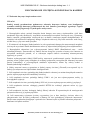
2.7. Security recommendations for network architecture and configuration
WARNING!
Below are shown security recommendations for network architecture and configuration
of CCTV systems that are connected to the Internet to reduce the risk
of unauthorized interference with the system by a third party.
1. Absolutely change the default passwords and user names (if the device gives this possibility) of
all applied network devices (recorders, cameras, routers, network switches, etc.) to the
severely complexity password. Use lowercase and uppercase letters, numbers, and special characters
if there is such possibility.
2. Depending on the available functionality in the order to restrict access to the used network devices at
the administrator account level, it is recommended to configure the users accounts accordingly.
3. Do not use DMZ function (Demilitarized zone) in your router. Using that function you open the
access to recorder system from the Internet on all ports, which gives possibility for an unauthorized
interference with the system.
Instead of DMZ use port forwarding redirect only the ports which are necessary for the performance
of the connection (detailed information about ports of communication in different models of recorders,
cameras, etc. can be found in the operating instructions).
4. Use routers with firewall function and make sure it is enabled and properly configured.
5. It is recommended to change the default network communication port numbers of used devices
if there is such possibility.
6. If used network devices has a UPnP feature and it is not used, turn it off.
7. If used network devices has a P2P feature and it is not used, turn it off.
8. If used network devices support HTTPS protocol for connection, it is recommended to use it.
9. If used network devices support IP filtering for authorized connections function, it is recommended
to use it.
10. If used recorder has two network interfaces it is recommended to use both of them to physically
separate network for cameras and network for Internet connection. The only device in the system,
accessible from Internet will be recorder - there will be no physically access directly to any camera.

NVIP-9DN2018V/IR-1P - User’s manual (short) ver 1.1
All rights reserved © AAT Holding S.A.
14
NETWORK CONNECTION UTILIZING WEB BROWSER
3. NETWORK CONNECTION USING WEB BROSWER
3.1. Recommended PC specification for web browser connections
Requirements below apply to connection with an IP camera, assuming smooth image display in
3000x3000 resolution and 30 fps speed.
1. CPU Intel Core i3 3GHz or newer
2. RAM Memory min. 4 GB
3. Graphic card NVIDIA GeForce 1 GHz
4. OS Windows VISTA / 7 / 8
5. Network card 10/100/1000 Mb/s
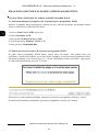
3.2. Connection with IP camera via web browser
You have to enter camera IP address in the address bar. When you connect to the camera, web browser
will download the applet for displaying images from the camera. In Internet Explorer before the first
logon you need to install "SurveillancePlugin.exe” addition. To do this, please click on the link
"Download" and when you get the download window, click "Run" button.
When the addition installer window appears, temporarily close the browser and click "Install" button.
After installation, launch a web browser and connect to the camera.

NVIP-9DN2018V/IR-1P - User’s manual (short) ver 1.1
All rights reserved © AAT Holding S.A.
15
If the installation fails, changing security settings for the IE browser is required. In order to do that,
please choose: Tools > Internet options > Security tab > Custom level and:
• Under Download unsigned ActiveX controls - select either Enable or Prompt
• Under Initialize and script ActiveX controls not marked as safe - select Enable or Prompt
You can also add the camera’s IP address to “trusted zone” and set lowest security level for it.
In addition, when working in Windows Vista/7/8 the ActiveX applet may be blocked by Windows
Defender or User account control. In such case you should allow to run this applet, or simply disable
these functions.
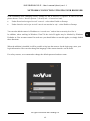
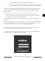
When the addition is installed it will be possible to log into the camera. On the login page, enter your
login information. Here can also change the language of the camera interface can be maid.
For safety reasons, we recommend to change the default password and user name.
NETWORK CONNECTION UTILIZING WEB BROWSER

NVIP-9DN2018V/IR-1P - User’s manual (short) ver 1.1
All rights reserved © AAT Holding S.A.
16
USING AND CONFIGURING
4. USING AND CONFIGURING
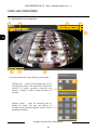
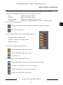
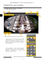
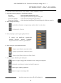
4.1. The Remote Preview Interface
1. Icon that enables the image display options panel:
USING AND CONFIGURING
8. 6. 7.
"Mount type" - icons for determining the way of
mounting the camera. The right choice affects the
selection of image geometry correction and
allows to display it with as little distortion as
possible
"Display mode" - icons for choosing how to
display the image. The type and number of
available display options depends on the chosen
installation location.
4.
5.
3.
1. 2.

NVIP-9DN2018V/IR-1P - User’s manual (short) ver 1.1
All rights reserved © AAT Holding S.A.
17
2. The selection buttons to select the stream to be displayed in the Remote Preview window.
3. Buttons for selecting the operating mode and configure the camera:
Live - enables preview live stream
Playback - displays the playback panel
Remote Setting - displays the configuration panel camera
Local Setting - displays the configuration panel of paths to snapshots folders
4. Icon to access to the camera:
5. Icon to enable/disable panel to set the image parameters:
6. Icons for selecting the operating mode
7. Icons icons that control additional functions
USING AND CONFIGURING
The panel is able to adjust the hue,
brightness, contrast, color saturation and
sharpness (clarity).
- enables the display of the video stream
- disables the display of the video stream
- sets full screen
- enables and disables the record a video stream on your computer
- performs a screenshot and saves on your computer
- enables and disables the volume control options
- enables and disables audio transmission
- displays information about the logged in user and the version of the applet
- logout from the camera

NVIP-9DN2018V/IR-1P - User’s manual (short) ver 1.1
All rights reserved © AAT Holding S.A.
18
ELECTRIC CONNECTORS AND RESTORING FACTORY DEFAULTS
8. Live Preview window.
Double-clicking on the live view window enables the display of the image on the full screen.
Additionally, depending on the display mode selected previously (see point 1), it is possible to modify
the display method: rotation, selection of the field of view, zooming (virtual PTZ). These operations are
carried out using the mouse, by pressing and holding the left key and dragging the mouse.
5. ELECTRIC CONNECTORS
5.1. Connecting of the alarm input.
5.1. Connecting of the alarm output.
6. RESTORING FACTORY DEFAULTS
6.1. Software restore to factory defaults
Camera NVIP-9DN2018V/IR-1P allows you to reset your settings to the factory values. To restore the
camera settings to the default, go to the "Load Default" tab (Remote Setting -> Advanced -> Load
Default). Then select options and functions of the camera whose settings are to be reset and press the
"Save" button.
After about 30 seconds, you can reconnect to the camera (at the current IP address, as long as it was not
reset network settings or on the default IP address).
Note: To make a software restore factory settings, you must be logged in as "root".
6.2 Hardware restore to factory defaults
You can use the RESET button located on the camera cable to reset the camera's settings. To reset the
defaults using the RESET button, press and hold for about 5 seconds.
After about 30 seconds, you will be able to reconnect to the camera at the default IP address.
Trigger contact
signaling device
Max. load 0.3A
signaling device power supply
12VDC or 24VAC max.

NVIP-9DN2018V/IR-1P - User’s manual (short) ver 1.1
All rights reserved © AAT Holding S.A.
19
ELECTRIC CONNECTORS AND RESTORING FACTORY DEFAULTS
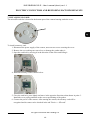
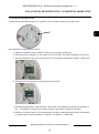
7. INSTALLING SD CARD
The microSD card slot is located in the bottom part of the camera housing under the cover:
To install a memory card:
1. Disconnect the power supply of the camera, unscrew two screws securing the cover
2. Remove the cover taking care not to lose or damage the gasket under it
3. Open the card lock by moving it in the direction of the arrow and lifting it
4. Install the memory card as shown below:
5. Close the card lock, press lightly and move in the opposite direction to that shown in point. 3.
Install the cover paying attention to the correct positioning of the gasket.
6. Connect the power of the camera. After starting the camera, the memory card will be
recognized and its status can be checked in the tab "Device -> SD card"

26.09.2018 TF, MK v1.1
AAT Holding S.A.
431 Pulawska St., 02-801 Warsaw, Poland
tel.: +4822 546 07 00, fax: +4822 546 07 59
www.novuscctv.com
Strona jest ładowana ...
Strona jest ładowana ...
Strona jest ładowana ...
Strona jest ładowana ...
Strona jest ładowana ...
Strona jest ładowana ...
Strona jest ładowana ...
Strona jest ładowana ...
Strona jest ładowana ...
Strona jest ładowana ...
Strona jest ładowana ...
Strona jest ładowana ...
Strona jest ładowana ...
Strona jest ładowana ...
Strona jest ładowana ...
Strona jest ładowana ...
Strona jest ładowana ...
Strona jest ładowana ...
Strona jest ładowana ...
Strona jest ładowana ...
-
 1
1
-
 2
2
-
 3
3
-
 4
4
-
 5
5
-
 6
6
-
 7
7
-
 8
8
-
 9
9
-
 10
10
-
 11
11
-
 12
12
-
 13
13
-
 14
14
-
 15
15
-
 16
16
-
 17
17
-
 18
18
-
 19
19
-
 20
20
-
 21
21
-
 22
22
-
 23
23
-
 24
24
-
 25
25
-
 26
26
-
 27
27
-
 28
28
-
 29
29
-
 30
30
-
 31
31
-
 32
32
-
 33
33
-
 34
34
-
 35
35
-
 36
36
-
 37
37
-
 38
38
-
 39
39
-
 40
40


AAT NVIP-9DN2018V/IR-1P Instrukcja obsługi
- Kategoria
- Kamery ochrony
- Typ
- Instrukcja obsługi
w innych językach
- English: AAT NVIP-9DN2018V/IR-1P User manual
Powiązane dokumenty
-
Novus NVIP-4V-8002M Instrukcja obsługi
-
-
-
-
-
-
-
-
-