

0 | Page
LA GARD SERIES 700
System User Guide
For Models 701-705

dormakaba USA Inc. System User Guide 7040.1121 Rev E2 10/22 | 1
Table of Contents
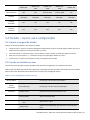
1 Introduction .............................................................................................. 6
1.1 Approved Standards ................................................................................................................... 6
1.2 Electrical Precautions ................................................................................................................ 7
1.3 Tools ............................................................................................................................................. 7
2 Typical System Layout (Single & Multi) ............................................... 8
2.1 Safe Lock Hardware ................................................................................................................... 9
2.2 System Components .................................................................................................................. 9
2.2.1 Keypad .......................................................................................................................................................... 9
2.2.2 Multiplexer .................................................................................................................................................. 9
2.2.3 Safe Lock ..................................................................................................................................................... 9
2.2.4 AC Adapter ................................................................................................................................................. 9
2.2.5 Battery Box................................................................................................................................................. 9
2.2.6 Alarm Box .................................................................................................................................................... 9
2.2.7 Reset Box................................................................................................................................................... 10
2.2.8 Fob .............................................................................................................................................................. 10
2.2.9 Power Considerations ............................................................................................................................ 10
2.3 Getting Started ......................................................................................................................... 11
3 How to Use the System ......................................................................... 11
3.1 Keypad Model Definitions ......................................................................................................... 11
3.2 Keypad – Layout, Usage, and Settings .................................................................................. 14
3.2.1 Keypad Layout & General Usage ...........................................................................................................14
3.2.2 Using a Display Keypad – Menu Settings............................................................................................14
3.2.3 Using a Non-Display Keypad - # Commands .....................................................................................16
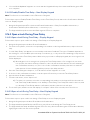
3.3 System Functions ..................................................................................................................... 16
3.3.1 System Info (Display Only) ..................................................................................................................... 17
3.3.2 Backlight Mode ........................................................................................................................................ 18
3.3.2.1 Backlight Mode – Display Keypad ....................................................................................................................18
3.3.2.2 Backlight Mode – 702 Keypad (Non-Display) ...............................................................................................18
3.3.3 Buzzer Mode ............................................................................................................................................. 18
3.3.3.1 Buzzer Mode – Display Keypad .........................................................................................................................18
3.3.3.2 Buzzer Mode – Non-Display Keypad ............................................................................................................... 19
3.3.4 Combination Length ................................................................................................................................19

dormakaba USA Inc. System User Guide 7040.1121 Rev E2 10/22 | 2
3.3.4.1 Combo Length – Display Keypad ..................................................................................................................... 19
3.3.4.2 Combo Length – Non-Display Keypad............................................................................................................ 19
3.3.5 Force Change Combination ...................................................................................................................19
3.3.5.1 Force Change Combination – Display Keypad ............................................................................................. 20
3.3.5.2 Force Change Combination – Non-Display Keypad ................................................................................... 20
3.3.6 User Mode ................................................................................................................................................. 20
3.3.6.1 User Mode – Display Keypad............................................................................................................................ 20
3.3.6.2 User Mode – Non-Display Keypad ................................................................................................................... 21
3.3.7 Credential Mode (703B, 704B, and 705 Models Only) ..................................................................... 21
3.3.8 Duress Mode (Silent Alarm) .................................................................................................................. 21
3.3.8.1 Duress Mode – Display Keypad ........................................................................................................................ 21
3.3.8.2 Duress Mode – Non-Display Keypad ............................................................................................................. 22
3.3.9 Input Signal ............................................................................................................................................... 22
3.3.9.1 Input Signal – Display Keypad ......................................................................................................................... 22
3.3.9.2 Input Signal – Non-Display Keypad ............................................................................................................... 23
3.4 Users .......................................................................................................................................... 23
3.4.1 Lock User Types........................................................................................................................................ 23
3.4.1.1 Master ................................................................................................................................................................... 23
3.4.1.2 Manager ............................................................................................................................................................... 24
3.4.1.3 Standard Users ................................................................................................................................................... 24
3.4.2 User Privileges .......................................................................................................................................... 24
3.4.2.1 User Privileges – Access Lock........................................................................................................................... 24
3.4.2.2 User Privileges – Audit Lock ............................................................................................................................ 25
3.4.2.3 User Privileges – Time Delay Override with Combination ......................................................................... 25
3.4.2.4 User Privileges – Time Delay Override with Fob Credential ..................................................................... 25
3.4.3 Assigning User IDs and Privileges ........................................................................................................ 28
3.4.3.1 Add User – Display Keypad .............................................................................................................................. 28
3.4.3.2 Add User – Non-Display Keypad ..................................................................................................................... 29
3.4.4 Edit User .................................................................................................................................................... 29
3.4.4.1 Edit User – Display Keypad .............................................................................................................................. 29
3.4.4.2 Edit User – Non-Display Keypad..................................................................................................................... 30
3.4.5 Delete User ................................................................................................................................................ 31
3.4.5.1 Delete User – Display Keypad ........................................................................................................................... 31
3.4.5.2 Delete User – Non-Display Keypad ................................................................................................................. 31
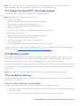
3.5 Install (Electronically Pair) a Lock and Keypad .................................................................... 31
3.5.1 Install (Electronically Pair) Lock and OLED Display Keypad .......................................................... 31
3.5.2 Install (Electronically Pair) Lock and non-Display Keypad ............................................................ 32
3.5.2.1 Standard Install Process ................................................................................................................................... 32

dormakaba USA Inc. System User Guide 7040.1121 Rev E2 10/22 | 3
3.5.2.2 Install with a Preconfigured User ................................................................................................................... 33
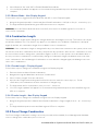
3.6 Open a Lock .............................................................................................................................. 34
3.6.3 Open a Lock – Display Keypad ............................................................................................................. 34
3.6.4 Open a Lock – Non-Display Keypad .................................................................................................... 34
3.6.5 Open a Lock – Remote Disable ............................................................................................................. 34
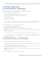
3.7 Change Combination ............................................................................................................... 35
3.7.1 Change Combination – Display Keypad .............................................................................................. 35
3.7.2 Change Combination – Non-Display Keypad .................................................................................... 35
3.8 Reinstall Keypad ...................................................................................................................... 36
3.9 Change Time/Date/DST ......................................................................................................... 36
3.9.1 Change Time/Date/DST – Display Keypad ....................................................................................... 36
3.9.2 Change Time/Date/DST – Non-Display Keypad .............................................................................. 37
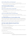
3.10 Battery Levels......................................................................................................................... 37
3.10.1 Low Battery Warning ........................................................................................................................... 37
3.10.1.1 Low Battery Warning – Display Keypad ...................................................................................................... 37
3.10.1.2 Low Battery Warning – Non-Display Keypad ............................................................................................ 38
3.10.2 Critical Low Battery Warning ............................................................................................................ 38
3.10.2.1 Critical Low Battery Warning – Display Keypad ....................................................................................... 38
3.10.2.2 Critical Low Battery Warning – Non-Display Keypad ............................................................................. 38
3.10.3 Replacing Batteries in Critical Low Battery State ........................................................................ 38
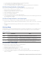
3.11 View Audits (Display Keypad Only) ..................................................................................... 38
3.12 Wrong Try Penalty .................................................................................................................. 39
3.13 Locks ........................................................................................................................................ 39
3.13.1 Physical Installation of a Lock ............................................................................................................. 39
3.13.2 Uninstall (Electronically Un-pair) a Lock .......................................................................................... 39
3.13.2.1 Uninstall a Lock – Display Keypad ................................................................................................................. 39
3.13.2.2 Uninstall a Lock – Non-Display Keypad ....................................................................................................... 40
3.13.3 Reset a Lock ........................................................................................................................................... 40
3.13.3.1 Master Reset – Display Keypad ..................................................................................................................... 40
3.13.3.2 Master Reset – Non-Display Keypad ............................................................................................................ 41
3.13.3.3 Mechanical Reset............................................................................................................................................... 41
3.14 Time Delay ............................................................................................................................... 41
3.14.1 Enable/Disable Time Delay ...................................................................................................................41
3.14.1.1 Enable/Disable Time Delay – Display Keypad .............................................................................................. 41
3.14.1.2 Time Delay Count Mode – Display Keypad .................................................................................................. 42
3.14.1.3 Enable/Disable Time Delay – Non-Display Keypad ................................................................................... 43
3.14.2 Open a Lock During Time Delay .......................................................................................................... 43

dormakaba USA Inc. System User Guide 7040.1121 Rev E2 10/22 | 4
3.14.2.1 Open a Lock During Time Delay – Display Keypad .................................................................................... 43
3.14.2.2 Open a Lock During Time Delay – Non-Display Keypad ........................................................................... 43
3.14.3 Cancel a Time Delay .............................................................................................................................. 44
3.14.3.1 Cancel a Time Delay – Display Keypad ......................................................................................................... 44
3.14.3.2 Cancel a Time Delay – Non-Display Keypad ............................................................................................... 44
3.14.4 Allow Time Delay Override .................................................................................................................. 44
3.14.4.1 Allow Time Delay Override – Display Keypad ............................................................................................ 44
3.14.4.2 Allow Time Delay Override – Non-Display Keypad .................................................................................. 45
3.14.5 Open Lock During Time Delay Using Override with Combo ......................................................... 45
3.14.5.1 Open Lock During Time Delay Using Override with Combo – Display Keypad .................................... 45
3.14.5.2 Open Lock During Time Delay Using Override with Combo – Non-Display Keypad ........................... 45
3.14.6 Open Lock During Time Delay Using Override with FOB .............................................................. 45
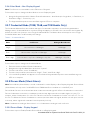
3.15 Auto Open................................................................................................................................ 47
3.15.1 Aspects of Auto Open ........................................................................................................................... 47
3.15.1.1 Auto Open Interactions with other features ............................................................................................... 48
3.15.1.2 Auto Open Feedback ........................................................................................................................................ 48
3.15.1.3 Auto Open Feedback with battery level low or critical............................................................................. 49
3.15.2 Configure Auto Open – Display Keypad ........................................................................................... 49
3.16 Assign Time Lock Schedules ................................................................................................. 50
(704 & 705 Models Only) .............................................................................................................. 50
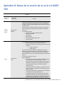
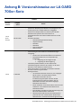
3.17 Time/Date Rules in LA GARD 700 Series Locks ................................................................. 50
3.18 FOB Identification Feedback................................................................................................. 52
3.18.1 FOB Credential Feedback .................................................................................................................... 52
3.18.2 FOB Low Battery and Critical Indicator .......................................................................................... 52
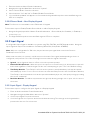
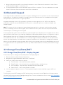
4 System Security ..................................................................................... 52
4.1 Data Encryption ........................................................................................................................ 52
4.2 Initial Combination Handling .................................................................................................. 53
5 LA GARD Software ............................................................................... 53
5.1 Adding a User with LA GARD Software ................................................................................. 53
5.2 Install a User into the Keypad ................................................................................................. 54
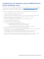
5.3 Firmware Update ..................................................................................................................... 54
5.4 Retrieve Audits ......................................................................................................................... 56
5.5 Add Time Lock Schedules using LA GARD Software (704 & 705 Models Only) ................ 57
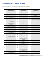
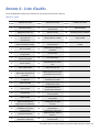
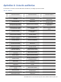
Appendix A: List of Audits ....................................................................... 58
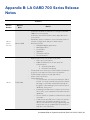
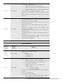
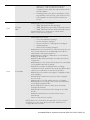
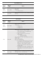
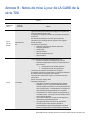
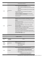
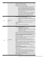
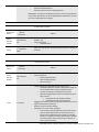
Appendix B: LA GARD 700 Series Release Notes ................................. 59

dormakaba USA Inc. System User Guide 7040.1121 Rev E2 10/22 | 5
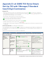
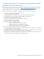
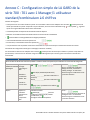
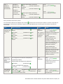
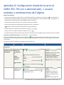
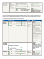
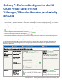
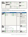
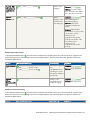
Appendix C: LA GARD 700 Series Simple Set-Up: 701 with 1
Manager/1 Standard User/6 Digit Combination .................................. 64
Appendix D: LA GARD 700 Series Simple Set-Up: 702 with 1
Manager/1 Standard User/6 Digit Combination .................................. 68

dormakaba USA Inc. System User Guide 7040.1121 Rev E2 10/22 | 6
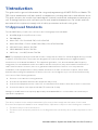
1 Introduction
This guide outlines general information for using and programming LA GARD 700 Series Models 701-
705 electric combination safe locks and all its components, including accessories and software client.
This guide assumes the installer has knowledge of electrical, mechanical, and computer concepts, as
well as having familiarity with safe lock systems and associated components. For reliable and safe
operation of the equipment, comply with all safety precautions outlined in this guide.
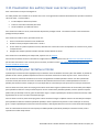
1.1 Approved Standards
The LA GARD family of safe locks conform to the following approved standards:
• UL 2058 (High Security Electronic Locks)
• EN 1300:2018
• Model: 705 – FCC ID: 2ASNP-705, IC ID: 24793-705
• Model: DKLG70X – FCC ID: 2ASNP-DKLG70X, IC ID: 24793-DKLG70X
• VDS 2395 Class 2, Models: 701-704
• SBSC 3880:2015, Models: 701-704
• CNPP A2p – Level B/E, Models: 701-704
Note: This equipment has been tested and found to comply with the limits for a Class B digital device, pursuant
to part 15 of the FCC Rules. These limits are designed to provide reasonable protection against harmful
interference in a residential installation. This equipment generates, uses, and can radiate radio frequency
energy and, if not installed and used in accordance with the instructions, may cause harmful interference to
radio communications. However, there is no guarantee that interference will not occur in a particular
installation. If this equipment does cause harmful interference to radio or television reception, which can be
determined by turning the equipment off and on, the user is encouraged to try to correct the interference by
one or more of the following measures:
• Reorient or relocate the receiving antenna
• Increase the separation between the equipment and receiver
• Connect the equipment into an outlet on a circuit different from that to which the receiver is connected
• Consult the dealer or an experienced radio/TV technician for help
Changes or modifications not expressly approved by dormakaba USA Inc. could void the user's authority to
operate the equipment.
This device contains license-exempt transmitter(s)/receiver(s) that comply with Innovation, Science and
Economic Development Canada’s license-exempt RSS(s). Operation is subject to the following two conditions:
1. This device may not cause interference.
2. This device must accept any interference, including interference that may cause undesired operation of the
device.

dormakaba USA Inc. System User Guide 7040.1121 Rev E2 10/22 | 7
L’émetteur/récepteur exempt de licence contenu dans le présent appareil est conforme aux CNR d’Innovation,
Sciences et Développement économique Canada applicables aux appareils radio exempts de licence.
L’exploitation est autorisée aux deux conditions suivantes :
1. L’appareil ne doit pas produire de brouillage.
2. L’appareil doit accepter tout brouillage radioélectrique subi, même si le brouillage est susceptible d’en
compromettre le fonctionnement.
CET APPAREIL EST CONFORME À LA NORME RSS INDUSTRIE CANADA EXEMPT DE LICENCE. Son
fonctionnement est soumis aux deux conditions suivantes:(1) Cet appareil ne doit pas provoquer
d’interférenceset(2) Cet appareil doit accepter toute interférence, y compris les interferences pouvant causer
un mauvais fonctionnement du dispositif. Cet appareil numérique de la classe [B] respecte toutes les exigences
du Réglement sur le matériel brouilleur du Canada.
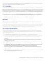
1.2 Electrical Precautions
Ensure alkaline batteries (where applicable) are new and in good condition; leaking batteries can cause damage
to components and can also cause serious bodily harm. Do not apply power (where applicable) before
completing all steps of the installation; doing so may damage the components. Ensure all power supplies are
plugged into grounded electrical receptacles that comply with local building code(s). When AC mains power is
required the power supply shall be installed in accordance with NFPA 70 and any applicable electrical codes.
1.3 Tools
dormakaba USA Inc. recommends having the following tools on hand to install LA GARD safe locks and their
components:
• Digital voltmeter
• Wire cutters and needle nose pliers
• Set of screwdrivers
• Drill and drill bits
• Automatic saw (band saw, hand saw)
• US or Metric taps
• File or equivalent tool
• All installation/hardware documentation for quick reference

dormakaba USA Inc. System User Guide 7040.1121 Rev E2 10/22 | 8
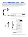
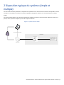
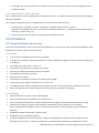
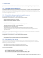
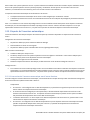
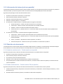
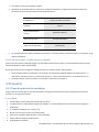
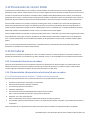
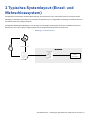
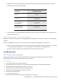
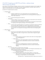
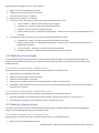
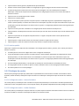
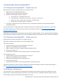
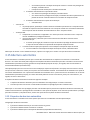
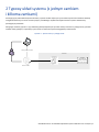
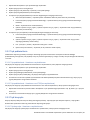
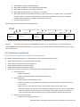
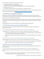
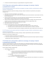
2 Typical System Layout (Single & Multi)
The following sub-sections review safe lock system components with related diagrams. Refer to each product’s
individual documentation for more detailed information on hardware installation and proper device usage.
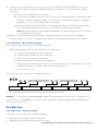
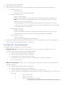
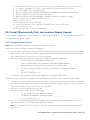
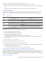
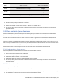
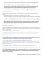
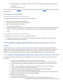
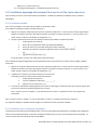
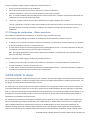
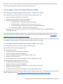
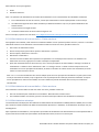
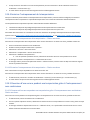
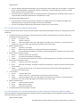
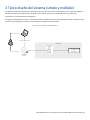
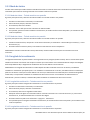
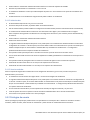
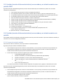
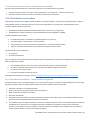
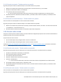
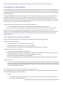
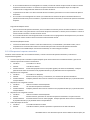
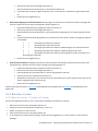
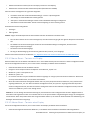
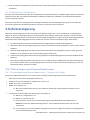
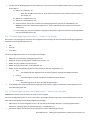
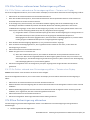
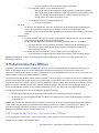
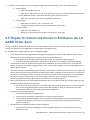
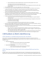
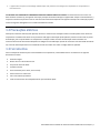
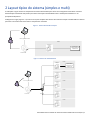
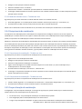
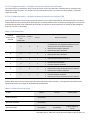
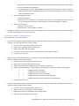
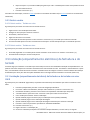
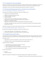
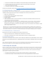
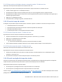
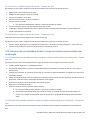
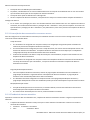
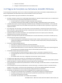
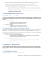
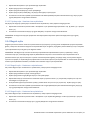
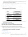
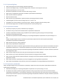
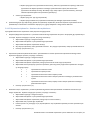
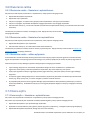
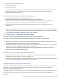
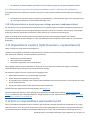
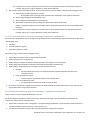
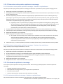
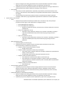
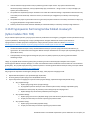
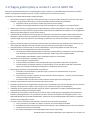
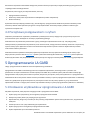
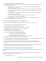
The following diagrams (Figures 1 and 2) show completed system layouts for both single and multi-lock
systems. Please note that your system may not include all components shown.
Figure 1 – Single Lock System
Battery box, alarm
box, or AC adaptor
LA G AR D Prg m C able
LA G AR D Key pad
Swingbolt Safe Lock
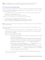
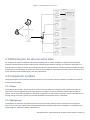
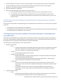
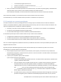
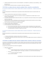
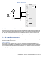
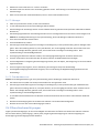
Figure 2 – Multi-Lock System
Battery box, alarm
box, or AC adaptor
LA G ARD Prg m Cable
LA G ARD Key pad
Lock #1
Multiplexor
Swingbol t Safe Lo ck
Swingbol t Safe Lo ck
Swingbol t Safe Lo ck
Swingbol t Safe Lo ck
Swingbol t Safe Lo ck

dormakaba USA Inc. System User Guide 7040.1121 Rev E2 10/22 | 9
2.1 Safe Lock Hardware
The LA GARD System components have been tested as compatible with the LA GARD system and should not
be substituted. Consult each component’s individual documentation for proper mounting, connectivity, and
installation. The safe itself must be appropriate for the lock hardware to provide maximum security; certain
makes and models of safes may not be appropriate for this LA GARD safe lock system. If unsure, consult with
dormakaba USA Inc. Sales or Support for further information.
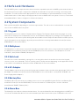
2.2 System Components
Each system may differ depending on customer requirements. The sub-sections outlined below cover the full
suite of the LA GARD safe lock system.
2.2.1 Keypad
The Keypad comes in two varieties: Display and non-Display. The Display variant shows messages on screen
while the non-Display version implements a series of LED flashes and beeps for messages. The Keypad is the
user interface for the entire system. All Keypads are available in both Tamper Evident and Serviceable options,
which will impact how the keypad is physically mounted. Refer to the Keypad Installation Guide (Document
#7033.0322) for more information.
2.2.2 Multiplexer
The Multiplexer is used in multi-lock systems and allows multiple safe locks to connect with the Keypad. Refer to
the Multiplexer Installation Guide (Document #7038.0521) for more information. The Multiplexer is not UL
evaluated. (Item/Order # 704033, “Multiplexer”)
2.2.3 Safe Lock
The safe lock is either a dead bolt, a spring bolt, or a swing bolt, that locks and unlocks when the Keypad
receives correct user credentials. This lock system comes in many varieties depending on the application. Refer
to the Safe Lock Installation Guide (Document # 7034.1121) for more information.
2.2.4 AC Adapter
The AC Adapter can be used to power the System where batteries alone would not be appropriate. Refer to the
AC Adapter Installation Guide (Document # 7037.0320) for more information. (Item/Order # 701107, “AC-
Power Supply Multi-Adapter”)
2.2.5 Battery Box
The Battery Box can serve as the secondary power source to the LA GARD System. Refer to the Battery Box
Installation Guide (Document #7035.0421) for more information. The Battery Box is not UL evaluated.
(Item/Order # 704055, “Battery Box”)
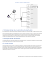
2.2.6 Alarm Box
The Alarm Box is a hard-wired external alarm device. If used, the Alarm Box must be plugged into the BAT port
of Lock #1. The Alarm Box allows for a remote disable input that can block the open command to the lock if

dormakaba USA Inc. System User Guide 7040.1121 Rev E2 10/22 | 10
asserted. Refer to the Alarm Box Installation Guide (Document #7036.0320) for more information. The Alarm
Box is not UL evaluated. (Item/Order # 704045, “Alarm Box”)
2.2.7 Reset Box
The Reset Box offers the capability to remove users and reset the Master Combination. To reset the lock, the
lock must be disconnected from any power source (AC Power or Battery) and powered from the Reset Box only.
The Reset Box must be connected to the BAT port on the back of the LA GARD safe lock. The Reset Box has a
green LED that will light when the reset function is performed. If a lock is already reset, applying the Reset Box
will not light the LED.
The Reset Box will only work in conjunction with LA GARD safe locks with a BAT port (will not work with older
model LG BASIC Series locks). Refer to the Reset Box User Guide (Document #7039.0521) for more
information. The Reset Box is not UL evaluated. (Item/Order # 704065, “Reset Box”)
2.2.8 Fob
The fob is used as a secondary Bluetooth® credential to user’s combination. The fob can be enrolled at the
Model 705 Keypad and assigned to a user.
For UL 2058 compliance, the fob credential was not evaluated by UL. However, if a fob credential is employed,
it’s required to be accompanied by a user combination to open a lock. The fob cannot be used as sole means to
operate and open the lock. (Item/Order # 890165, “FOB (Bluetooth Enabled Credential)”)
2.2.9 Power Considerations
The system common power across all components. As long as 9V DC power is supplied to the system, the
system will work as intended. It is unnecessary to apply multiple sources of power to some or all components.
Some considerations to follow:
• The standard-profile Keypad models require two 9V batteries can be inserted into the tray.
• The low-profile Keypad models require a Battery Box or Power Adapter accessory is required for power.
These keypads include an emergency battery connection to apply power from outside of the safe
container.
• A LA GARD 700 Series Battery Box accessory is available to be attached inside the secure container to
grant power to the system.
• A LA GARD 700 Series Alarm Box can be connected to the primary lock to provide power to the system.
This Alarm Box must be physically located in the secure side of the container.
• A LA GARD 700 Series AC/DC Power Adapter accessory can be used to apply line power to the system.
The power adapter can be connected to any lock’s BAT port in a multi-lock configuration.
• In multi-lock installations while using a Multiplexer, it is strongly recommended that the AC/DC Power
Adapter be used.
• When resetting a lock via the LA GARD Series 700 Reset Box, a 9V battery must be inserted into the Reset
Box to apply power for the short duration usage.

dormakaba USA Inc. System User Guide 7040.1121 Rev E2 10/22 | 11
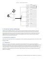
2.3 Getting Started
This section outlines typical use of a System with a single or multi-lock/single or multi-user setup with
references to various sections found through this document.
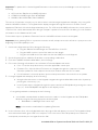
Follow these steps to get started implementing a System:
1. Identifying System Requirements
a. Identify Required System Components – Review Section 2.2 “System Components” for
installation procedures regarding each component of a System. For single lock Systems, the use
of a Multiplexer is not required.
b. Identify Required System Functions – Review Section 3.3 “System Functions” for an overview of
how each user is authorized to use the system.
c. Identify Required User Types and Privileges – Read Section 3.4.1 “Lock User Types” and 3.4.2
“User Privileges” for an overview how each user is authorized to use the system.
2. Configure the System
a. Install (Electronically Pair) Lock(s) – Read Section 3.5 “Install (Electronically Pair) a Lock and
Keypad” for instructions on performing this step.
b. Add Users – Read Section 3.4.3 “Assigning User IDs and Privileges” for instructions on adding all
non-Master users.
c. Change Master User Combination – Read Section 3.7 ”Change Combination” for instructions in
changing the Combination for the Master User.
3. Customize the System
a. For Keypad Models 702-705, Set Date and Time – Read Section 3.9 “Change Time/Date/DST”
for instructions on setting or re-setting the Time.
b. Configure other System Functions – Instructions for configuring custom options are provided in
Section 3.3 “System Functions”.
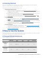
3 How to Use the System
This section outlines how to use the installed system and how to execute specified functions. Please note that
your installation may not include everything outlined in this section.
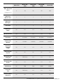
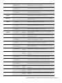
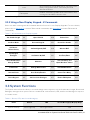
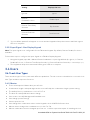
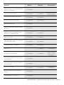
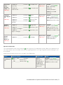
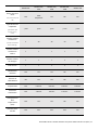
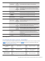
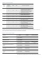
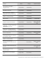
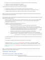
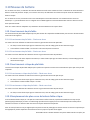
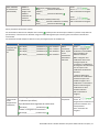
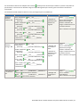
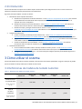
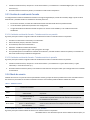
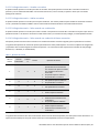
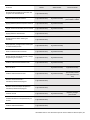
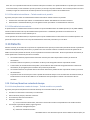
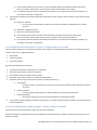
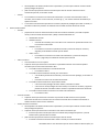
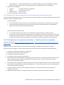
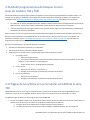
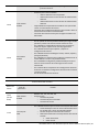
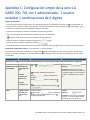
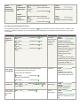
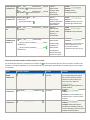
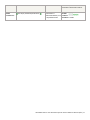
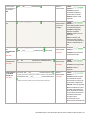
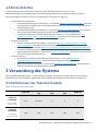
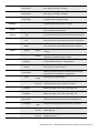
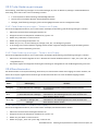
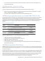
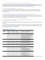
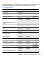
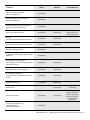
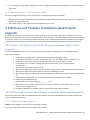
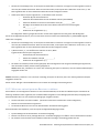
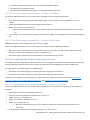
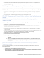
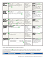
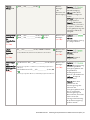
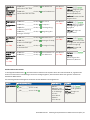
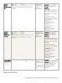
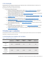
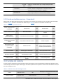
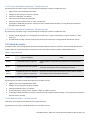
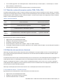
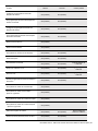
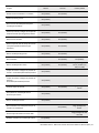
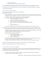
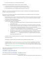
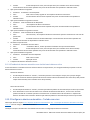
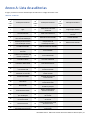
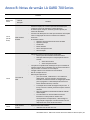
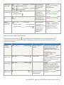
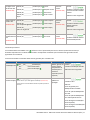
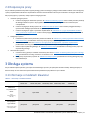
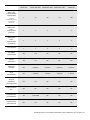
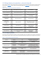
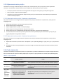
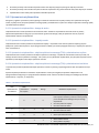
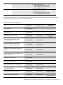
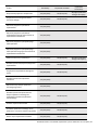
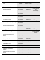
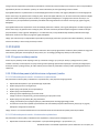
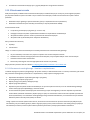
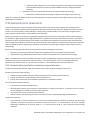
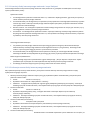
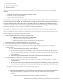
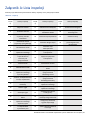
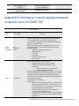
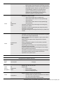
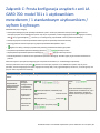
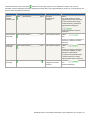
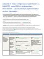
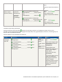
3.1 Keypad Model Definitions
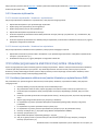
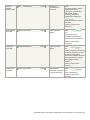
Table 1 – Keypad Model Definitions
Model 701 Model 702,
702D
Model 703,
703B
Model 704,
704B Model 705
OLED Display
Keypad
(1.28”, Monochrome,
128 x 64)
No 702D only Yes Yes Yes
Compatible
Lock Types
⸸(Swing Bolt, Dead
Bolt, Spring Bolt)
⸸All ⸸All ⸸All ⸸All ⸸All

dormakaba USA Inc. System User Guide 7040.1121 Rev E2 10/22 | 12
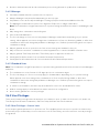
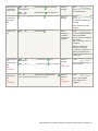
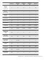
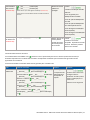
Model 701 Model 702,
702D
Model 703,
703B
Model 704,
704B Model 705
Max. # of Total
Users
(includes Master and
Manager users)
3 30 30 50 100
Max. # of
Master Users 1 1 1 1 1
Max. # of
Managers 1 1 1 2 2
# of Locks 1 1 2 5 5
Dual-User
Mode No Yes Yes Yes Yes
Reset Function Yes Yes Yes Yes Yes
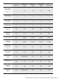
Time Delay No 0-99 Min. 0-99 Min. 0-99 Min. 0-99 Min.
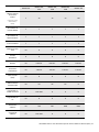
Confirmation
Window No 1-60 Min. 1-60 Min. 1-60 Min. 1-60 Min.
Time Delay
Override
(TDO)
No Yes Yes Yes Yes
TDO with BLE
Key fob No No No No Yes
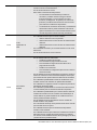
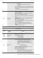
Programmable
at Keypad Yes 702D Only Yes Yes Yes
Programmable
by PC No Yes Yes Yes Yes
Audit Events No 500 500 2000 6000
View Audit
Trail No 702D Only Yes Yes Yes
Downloadable
Audit Trail No Yes Yes Yes Yes

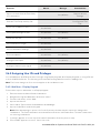
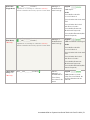
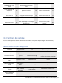
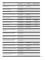
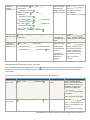
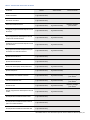
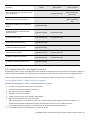
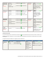
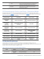
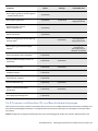
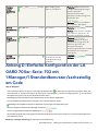
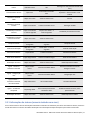
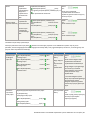
dormakaba USA Inc. System User Guide 7040.1121 Rev E2 10/22 | 13
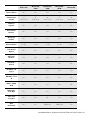
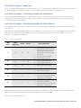
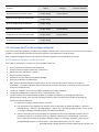
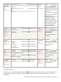
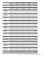
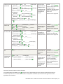
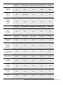
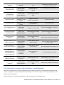
Model 701 Model 702,
702D
Model 703,
703B
Model 704,
704B Model 705
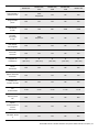
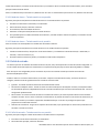
Duress Alarm No Yes Yes Yes Yes
Combination
Length
11
(2id + 6-9)
11
(2id + 6-9)
11
(2id + 6-9)
11
(2id + 6-9)
11
(2id + 6-9)
Back Lit
Keypad No Yes Yes Yes Yes
Bolt Switch
Option* No Yes Yes Yes Yes
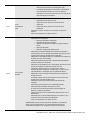
Wrong Try
Penalty Yes Yes Yes Yes Yes
Battery Power 2 x 9V 2 x 9V 2 x 9V 2 x 9V 2 x 9V
Low-Profile
Option No Yes Yes Yes No
AC Power
Option* Yes Yes Yes Yes Yes
VdS 2396 –
Class 2 Yes Yes Yes Yes No
UL 2058 – UL
Type 1 Yes Yes Yes Yes Yes
EN1300 – Level
B Yes Yes Yes Yes No
SBSC – 3880-
2015 Yes Yes Yes Yes No
CNPP q2p –
Level B/E Yes Yes Yes Yes No
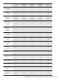
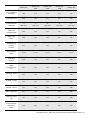
Time Lock
Schedule No No No Yes Yes
Dual
Credential No No 703B only 704B only Yes

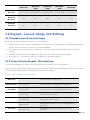
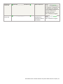
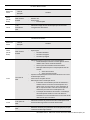
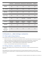
dormakaba USA Inc. System User Guide 7040.1121 Rev E2 10/22 | 14
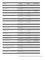
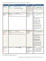
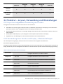
Model 701 Model 702,
702D
Model 703,
703B
Model 704,
704B Model 705
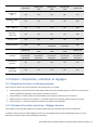
Warranty 2yr from DoM 2yr from DoM 2yr from DoM 2yr from DoM 2yr from DoM
Extended
Warranty* Yes Yes Yes Yes Yes
Updatable
Firmware Yes Yes Yes Yes Yes
*Sold separately
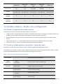
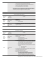
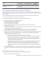
3.2 Keypad – Layout, Usage, and Settings
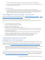
3.2.1 Keypad Layout & General Usage
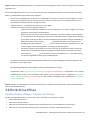
Below is a list of buttons and their functions on the Keypad:
• Number Pad – Can be used for entering User combinations, # commands (for non-Display Keypads) and
specific optional functions on screen (for Display Keypads)
• Pound Key (#) – Is used to return to a previous screen, or to wake up the Keypad without entering a
number
• Up and Down Arrows (˄˅) – Navigate through options with these (for Display Keypads)
• Return Key (←) – Confirms a selection or complete a command sequence
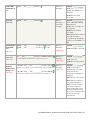
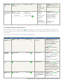
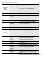
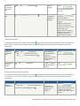
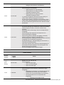
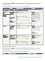
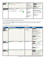
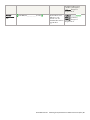
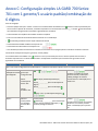
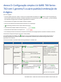
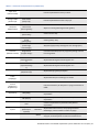
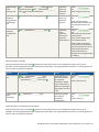
3.2.2 Using a Display Keypad – Menu Settings
To enter the Main Menu, press any non-numeric button followed by your user credentials.
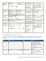
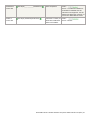
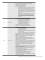
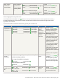
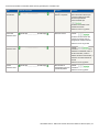
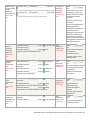
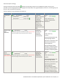
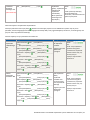
Below is a table outlining each Menu Setting and sub-setting within the Keypad display interface. Note that the
menu available changes based on the User Role and/or User Privileges.
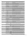
Table 2 – Menu Settings (Display Keypad)
Open Lock
Allows the User to open a lock.
Change combo New Combo
Allows the User to change their combination.
Time/Date Time Format
Choose between a 12 and 24HR time format.
Date Format
Change the date format.
Set Time Date
Change the time and date.
Observe DST
Select Enable/Disable to observe Daylight Saving
Time (DST).
Time Lock Assign Access
Designate a lock as 24/7 or assign one of two
schedules.

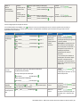
dormakaba USA Inc. System User Guide 7040.1121 Rev E2 10/22 | 15
View Access 1
View the access of schedule #1.
View Access 2
View the access of schedule #2.
View Holiday
View the assigned holidays.
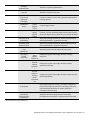
Audits*
Displays transactional data from a lock.
PC Link*
Connects the Keypad to a PC running the LA GARD
software client.
Users Add
Add a User based on their User ID.
Edit
Edit a User based on their User ID.
Delete
Delete a User based on their User ID.
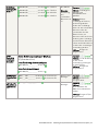
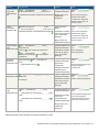
System Sys Info Keypad Displays Battery Status, Firmware version, Model
and Serial #s.
Lock Shows firmware versions, serial numbers, port & Lock
# and Open Count.
Backlight
Toggle the Backlight On and Off.
Buzzer
Toggle the Buzzer sound On and Off.
TD Cnt Mode
Set counting period to count up, down or not show
time in the periods.
Combination Combo
Length Determines the length of a combination.
Force
Change
Determines whether or not new Users will have to
change their combination after initial login (choose
Yes/No)
User Mode
Choose between Single, Dual and Dual + Mgr.
Cred Mode
Choose between Single, Dual and Dual + Mgr.
Duress Mode*
Enables/Disables Duress Mode (Silent Alarm).
Input Signal Disable
Open
Configures the Input Signal for Remote Disable
function.
Dly
Override
Configures the Input Signal for Time Delay Override
function.
Dual
Override
Configures the Input Signal for Dual User Override
function

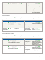
dormakaba USA Inc. System User Guide 7040.1121 Rev E2 10/22 | 16
Locks
Choose between Install, Uninstall, TL Schedule, Time
Delay configuration times, Time Delay Override
allowed and Reset.
FW Update
Enables a firmware update when connected to a PC
running the LA GARD software client.
*Not evaluated by UL
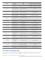
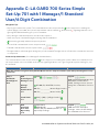
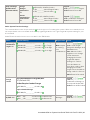
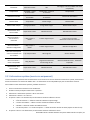
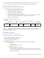
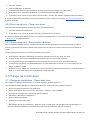
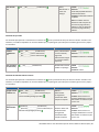
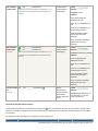
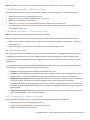
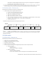
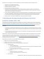
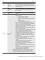
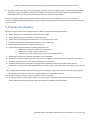
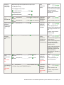
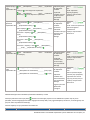
3.2.3 Using a Non-Display Keypad - # Commands
Below is a table outlining each # Command and their function for non-Display Keypads. For more details,
please refer to Appendix C (contains 701 model # commands) and Appendix D (contains 702 model #
commands).
Table 3 – # Commands (non-Display Keypad)
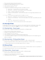
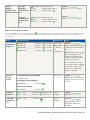
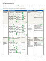
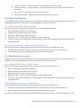
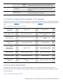
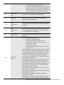
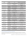
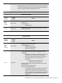
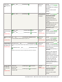
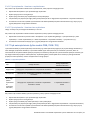
3.3 System Functions
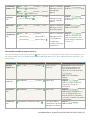
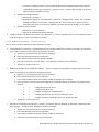
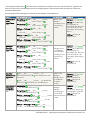
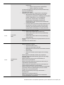
The System menu allows the User to view and change various aspects, such as Combination length, Buzzer and
Backlight, amongst other options. Below is a table that outlines Buzzer, LED, and Screen Messages in response
to certain events.
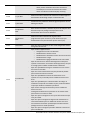
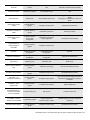
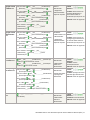
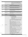
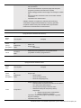
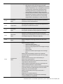
Table 4 – Buzzer, LED, and Screen Message(s)
Event Buzzer LED Screen Message(s) (Display Only)
System wakeup Short high beep Short green flash N/A
Set Combo Length #11 Open PC Link #30 Delete User #56
Set User Mode #12 Reinstall Keypad #32 Reset User Combo #57
Set Duress
(Silent Alarm) #14 Set Backlight On/Off #40 Observe DST #63
Input Signal
Configure #16 Set Buzzer On/Off #41 Set Time/Date #65
Force Combination
Change On/Off #17 Add User #50 Set Time Delay and
Open Windows Values #72
Install Lock #22 Change Own Combo #52 Set TDO Allowance #73
Uninstall Lock #23 User Enable/Disable #54 Cancel Time Delay #74
Reset Keypad #25 Set User Lock Privileges #55 Enable FW Update #99

dormakaba USA Inc. System User Guide 7040.1121 Rev E2 10/22 | 17
Event Buzzer LED Screen Message(s) (Display Only)
Key press Short beep Short green or red flash High beep + Green flash = Valid Key
Low Beep + Red flash = Invalid Key
Valid command
response 3 short high beeps 3 short green flashes Success
Invalid command
response 3 short low beeps 3 short red flashes Invalid Message
Wrong Try Penalty 2 short low beeps
- every 10 seconds
2 short red flashes –
every 10 seconds Wrong Try Penalty
Wrong Try Penalty
ends 2 short high beeps 2 short green flashes
Time Delay 1 low beep – every
10 seconds
1 red flash – every 10
seconds Time Delay
Confirm window 1 high beep –
every 10 seconds
1 green flash – every 10
seconds Confirmation Window
Low Battery 2 low beeps 2 red flashes Low Battery
Critical Low Battery 3 long low beeps 3 long red flashes Critical Low Battery
Master Reset 3 short high beeps 3 short green flashes Reset Success
Power On – No lock
connected
5 medium to low
beeps 5 medium red flashes No Lock Found
Turn Power Off and Connect
Power On – Bad
configuration
5 medium to low
beeps 5 medium red flashes Bad Config
Power On/Wake Up –
Lock Connected but
Not Installed
1 medium low
beep Solid red LED Lock Detected
Power On – Keypad
not compatible 1 long low beep Continuous alternate
flashing red and green
Wrong Keypad Model Cannot
Install
Master reset 3 short high
beeps 3 short green flashes Reset Success
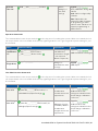
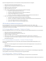
3.3.1 System Info (Display Only)
The System Info screen provides information related to the Keypad and safe locks connected to the System,
including Firmware version and Model number. Note: This information is only available to authorized users.
Follow these steps to navigate through the System Info menu:

dormakaba USA Inc. System User Guide 7040.1121 Rev E2 10/22 | 18
1. Enter and Authorized User ID and Combination.
2. Navigate through the Main Menu and select “System”.
3. Select “Sys Info” from the sub-menu.
4. Select between “Keypad” or “Lock”.
5. If “Keypad” is selected, the following information is available on screen:
• “Batt Status” – Displays battery level with a percentage
• “FW version” – Shows the current firmware version on the Keypad
• “Model” – Displays the Model # of the Keypad
• “S/N Part 1” and “S/N Part 2” – Shows the serial number of the Keypad (divided between two
screens)
6. If “Lock” is selected, the following information is available on screen:
• “FW version” – Displays the current firmware version on the safe lock
• “S/N Part 1” and “S/N Part 2” – Shows the serial number of the safe lock (divided between two
screens)
• “Port | Lock” – Represents the Port and Lock #s
• “Open Count” – Shows how many times the safe lock was opened
3.3.2 Backlight Mode
The Backlight illuminates whenever a key is pressed on the Keypad. By default, the Backlight setting is Off to
conserve battery power (if applicable). Note: This function is not available on the 701 series Keypad.
3.3.2.1 Backlight Mode – Display Keypad
Follow these steps to toggle the Backlight Mode On and Off on a Display Keypad:
1. Enter an Authorized User ID and Combination.
2. Navigate through the Main Menu and select “System”.
3. Select “Backlight” from the sub-menu.
4. Select between “On” and “Off” to Enable/Disable Backlight Mode.
5. “Success Mode updated” will appear on screen and the Keypad will beep three times and flash a green
LED once complete.
3.3.2.2 Backlight Mode – 702 Keypad (Non-Display)
Follow these steps to toggle the Backlight Mode On and Off on a 702 non-Display Keypad:
1. Using the Keypad, input #40 + Authorized User ID and Combination + Off (0) or On (1) + <return key> (←).
2. The Keypad will beep three times and flash a green LED once complete.
3.3.3 Buzzer Mode
The Buzzer provides sound to signal specific functional outcomes. The Buzzer Mode is active (on) by default. It
is recommended that the Buzzer is left on for Non-Display Keypads.
3.3.3.1 Buzzer Mode – Display Keypad
Follow these steps to toggle the Buzzer Mode On and Off on a Display Keypad:
1. Enter an Authorized User ID and Combination.
2. Navigate through the Main Menu and select “System”.
3. Select Buzzer from the sub-menu.
Strona się ładuje...
Strona się ładuje...
Strona się ładuje...
Strona się ładuje...
Strona się ładuje...
Strona się ładuje...
Strona się ładuje...
Strona się ładuje...
Strona się ładuje...
Strona się ładuje...
Strona się ładuje...
Strona się ładuje...
Strona się ładuje...
Strona się ładuje...
Strona się ładuje...
Strona się ładuje...
Strona się ładuje...
Strona się ładuje...
Strona się ładuje...
Strona się ładuje...
Strona się ładuje...
Strona się ładuje...
Strona się ładuje...
Strona się ładuje...
Strona się ładuje...
Strona się ładuje...
Strona się ładuje...
Strona się ładuje...
Strona się ładuje...
Strona się ładuje...
Strona się ładuje...
Strona się ładuje...
Strona się ładuje...
Strona się ładuje...
Strona się ładuje...
Strona się ładuje...
Strona się ładuje...
Strona się ładuje...
Strona się ładuje...
Strona się ładuje...
Strona się ładuje...
Strona się ładuje...
Strona się ładuje...
Strona się ładuje...
Strona się ładuje...
Strona się ładuje...
Strona się ładuje...
Strona się ładuje...
Strona się ładuje...
Strona się ładuje...
Strona się ładuje...
Strona się ładuje...
Strona się ładuje...
Strona się ładuje...
Strona się ładuje...
Strona się ładuje...
Strona się ładuje...
Strona się ładuje...
Strona się ładuje...
Strona się ładuje...
Strona się ładuje...
Strona się ładuje...
Strona się ładuje...
Strona się ładuje...
Strona się ładuje...
Strona się ładuje...
Strona się ładuje...
Strona się ładuje...
Strona się ładuje...
Strona się ładuje...
Strona się ładuje...
Strona się ładuje...
Strona się ładuje...
Strona się ładuje...
Strona się ładuje...
Strona się ładuje...
Strona się ładuje...
Strona się ładuje...
Strona się ładuje...
Strona się ładuje...
Strona się ładuje...
Strona się ładuje...
Strona się ładuje...
Strona się ładuje...
Strona się ładuje...
Strona się ładuje...
Strona się ładuje...
Strona się ładuje...
Strona się ładuje...
Strona się ładuje...
Strona się ładuje...
Strona się ładuje...
Strona się ładuje...
Strona się ładuje...
Strona się ładuje...
Strona się ładuje...
Strona się ładuje...
Strona się ładuje...
Strona się ładuje...
Strona się ładuje...
Strona się ładuje...
Strona się ładuje...
Strona się ładuje...
Strona się ładuje...
Strona się ładuje...
Strona się ładuje...
Strona się ładuje...
Strona się ładuje...
Strona się ładuje...
Strona się ładuje...
Strona się ładuje...
Strona się ładuje...
Strona się ładuje...
Strona się ładuje...
Strona się ładuje...
Strona się ładuje...
Strona się ładuje...
Strona się ładuje...
Strona się ładuje...
Strona się ładuje...
Strona się ładuje...
Strona się ładuje...
Strona się ładuje...
Strona się ładuje...
Strona się ładuje...
Strona się ładuje...
Strona się ładuje...
Strona się ładuje...
Strona się ładuje...
Strona się ładuje...
Strona się ładuje...
Strona się ładuje...
Strona się ładuje...
Strona się ładuje...
Strona się ładuje...
Strona się ładuje...
Strona się ładuje...
Strona się ładuje...
Strona się ładuje...
Strona się ładuje...
Strona się ładuje...
Strona się ładuje...
Strona się ładuje...
Strona się ładuje...
Strona się ładuje...
Strona się ładuje...
Strona się ładuje...
Strona się ładuje...
Strona się ładuje...
Strona się ładuje...
Strona się ładuje...
Strona się ładuje...
Strona się ładuje...
Strona się ładuje...
Strona się ładuje...
Strona się ładuje...
Strona się ładuje...
Strona się ładuje...
Strona się ładuje...
Strona się ładuje...
Strona się ładuje...
Strona się ładuje...
Strona się ładuje...
Strona się ładuje...
Strona się ładuje...
Strona się ładuje...
Strona się ładuje...
Strona się ładuje...
Strona się ładuje...
Strona się ładuje...
Strona się ładuje...
Strona się ładuje...
Strona się ładuje...
Strona się ładuje...
Strona się ładuje...
Strona się ładuje...
Strona się ładuje...
Strona się ładuje...
Strona się ładuje...
Strona się ładuje...
Strona się ładuje...
Strona się ładuje...
Strona się ładuje...
Strona się ładuje...
Strona się ładuje...
Strona się ładuje...
Strona się ładuje...
Strona się ładuje...
Strona się ładuje...
Strona się ładuje...
Strona się ładuje...
Strona się ładuje...
Strona się ładuje...
Strona się ładuje...
Strona się ładuje...
Strona się ładuje...
Strona się ładuje...
Strona się ładuje...
Strona się ładuje...
Strona się ładuje...
Strona się ładuje...
Strona się ładuje...
Strona się ładuje...
Strona się ładuje...
Strona się ładuje...
Strona się ładuje...
Strona się ładuje...
Strona się ładuje...
Strona się ładuje...
Strona się ładuje...
Strona się ładuje...
Strona się ładuje...
Strona się ładuje...
Strona się ładuje...
Strona się ładuje...
Strona się ładuje...
Strona się ładuje...
Strona się ładuje...
Strona się ładuje...
Strona się ładuje...
Strona się ładuje...
Strona się ładuje...
Strona się ładuje...
Strona się ładuje...
Strona się ładuje...
Strona się ładuje...
Strona się ładuje...
Strona się ładuje...
Strona się ładuje...
Strona się ładuje...
Strona się ładuje...
Strona się ładuje...
Strona się ładuje...
Strona się ładuje...
Strona się ładuje...
Strona się ładuje...
Strona się ładuje...
Strona się ładuje...
Strona się ładuje...
Strona się ładuje...
Strona się ładuje...
Strona się ładuje...
Strona się ładuje...
Strona się ładuje...
Strona się ładuje...
Strona się ładuje...
Strona się ładuje...
Strona się ładuje...
Strona się ładuje...
Strona się ładuje...
Strona się ładuje...
Strona się ładuje...
Strona się ładuje...
Strona się ładuje...
Strona się ładuje...
Strona się ładuje...
Strona się ładuje...
Strona się ładuje...
Strona się ładuje...
Strona się ładuje...
Strona się ładuje...
Strona się ładuje...
Strona się ładuje...
Strona się ładuje...
Strona się ładuje...
Strona się ładuje...
Strona się ładuje...
Strona się ładuje...
Strona się ładuje...
Strona się ładuje...
Strona się ładuje...
Strona się ładuje...
Strona się ładuje...
Strona się ładuje...
Strona się ładuje...
Strona się ładuje...
Strona się ładuje...
Strona się ładuje...
Strona się ładuje...
Strona się ładuje...
Strona się ładuje...
Strona się ładuje...
Strona się ładuje...
Strona się ładuje...
Strona się ładuje...
Strona się ładuje...
Strona się ładuje...
Strona się ładuje...
Strona się ładuje...
Strona się ładuje...
Strona się ładuje...
Strona się ładuje...
Strona się ładuje...
Strona się ładuje...
Strona się ładuje...
Strona się ładuje...
Strona się ładuje...
Strona się ładuje...
Strona się ładuje...
Strona się ładuje...
Strona się ładuje...
Strona się ładuje...
Strona się ładuje...
Strona się ładuje...
Strona się ładuje...
Strona się ładuje...
Strona się ładuje...
Strona się ładuje...
Strona się ładuje...
Strona się ładuje...
Strona się ładuje...
Strona się ładuje...
Strona się ładuje...
Strona się ładuje...
Strona się ładuje...
Strona się ładuje...
Strona się ładuje...
Strona się ładuje...
Strona się ładuje...
Strona się ładuje...
Strona się ładuje...
Strona się ładuje...
Strona się ładuje...
Strona się ładuje...
Strona się ładuje...
Strona się ładuje...
Strona się ładuje...
Strona się ładuje...
Strona się ładuje...
Strona się ładuje...
Strona się ładuje...
Strona się ładuje...
Strona się ładuje...
Strona się ładuje...
Strona się ładuje...
Strona się ładuje...
Strona się ładuje...
Strona się ładuje...
Strona się ładuje...
Strona się ładuje...
Strona się ładuje...
Strona się ładuje...
Strona się ładuje...
Strona się ładuje...
Strona się ładuje...
Strona się ładuje...
Strona się ładuje...
Strona się ładuje...
Strona się ładuje...
Strona się ładuje...
Strona się ładuje...
Strona się ładuje...
Strona się ładuje...
Strona się ładuje...
Strona się ładuje...
Strona się ładuje...
Strona się ładuje...
Strona się ładuje...
Strona się ładuje...
Strona się ładuje...
Strona się ładuje...
Strona się ładuje...
Strona się ładuje...
Strona się ładuje...
Strona się ładuje...
Strona się ładuje...
Strona się ładuje...
Strona się ładuje...
Strona się ładuje...
Strona się ładuje...
Strona się ładuje...
Strona się ładuje...
Strona się ładuje...
Strona się ładuje...
Strona się ładuje...
Strona się ładuje...
Strona się ładuje...
Strona się ładuje...
Strona się ładuje...
Strona się ładuje...
Strona się ładuje...
Strona się ładuje...
Strona się ładuje...
Strona się ładuje...
Strona się ładuje...
Strona się ładuje...
Strona się ładuje...
Strona się ładuje...
Strona się ładuje...
Strona się ładuje...
Strona się ładuje...
Strona się ładuje...
Strona się ładuje...
Strona się ładuje...
Strona się ładuje...
Strona się ładuje...
Strona się ładuje...
Strona się ładuje...
Strona się ładuje...
Strona się ładuje...
Strona się ładuje...
Strona się ładuje...
Strona się ładuje...
Strona się ładuje...
Strona się ładuje...
Strona się ładuje...
Strona się ładuje...
Strona się ładuje...
Strona się ładuje...
Strona się ładuje...
Strona się ładuje...
Strona się ładuje...
Strona się ładuje...
Strona się ładuje...
Strona się ładuje...
Strona się ładuje...
Strona się ładuje...
Strona się ładuje...
Strona się ładuje...
Strona się ładuje...
Strona się ładuje...
Strona się ładuje...
Strona się ładuje...
Strona się ładuje...
Strona się ładuje...
Strona się ładuje...
Strona się ładuje...
Strona się ładuje...
Strona się ładuje...
Strona się ładuje...
Strona się ładuje...
Strona się ładuje...
Strona się ładuje...
Strona się ładuje...
Strona się ładuje...
Strona się ładuje...
Strona się ładuje...
Strona się ładuje...
Strona się ładuje...
Strona się ładuje...
Strona się ładuje...
Strona się ładuje...
Strona się ładuje...
Strona się ładuje...
Strona się ładuje...
Strona się ładuje...
Strona się ładuje...
Strona się ładuje...
Strona się ładuje...
Strona się ładuje...
Strona się ładuje...
Strona się ładuje...
Strona się ładuje...
Strona się ładuje...
Strona się ładuje...
Strona się ładuje...
Strona się ładuje...
-
 1
1
-
 2
2
-
 3
3
-
 4
4
-
 5
5
-
 6
6
-
 7
7
-
 8
8
-
 9
9
-
 10
10
-
 11
11
-
 12
12
-
 13
13
-
 14
14
-
 15
15
-
 16
16
-
 17
17
-
 18
18
-
 19
19
-
 20
20
-
 21
21
-
 22
22
-
 23
23
-
 24
24
-
 25
25
-
 26
26
-
 27
27
-
 28
28
-
 29
29
-
 30
30
-
 31
31
-
 32
32
-
 33
33
-
 34
34
-
 35
35
-
 36
36
-
 37
37
-
 38
38
-
 39
39
-
 40
40
-
 41
41
-
 42
42
-
 43
43
-
 44
44
-
 45
45
-
 46
46
-
 47
47
-
 48
48
-
 49
49
-
 50
50
-
 51
51
-
 52
52
-
 53
53
-
 54
54
-
 55
55
-
 56
56
-
 57
57
-
 58
58
-
 59
59
-
 60
60
-
 61
61
-
 62
62
-
 63
63
-
 64
64
-
 65
65
-
 66
66
-
 67
67
-
 68
68
-
 69
69
-
 70
70
-
 71
71
-
 72
72
-
 73
73
-
 74
74
-
 75
75
-
 76
76
-
 77
77
-
 78
78
-
 79
79
-
 80
80
-
 81
81
-
 82
82
-
 83
83
-
 84
84
-
 85
85
-
 86
86
-
 87
87
-
 88
88
-
 89
89
-
 90
90
-
 91
91
-
 92
92
-
 93
93
-
 94
94
-
 95
95
-
 96
96
-
 97
97
-
 98
98
-
 99
99
-
 100
100
-
 101
101
-
 102
102
-
 103
103
-
 104
104
-
 105
105
-
 106
106
-
 107
107
-
 108
108
-
 109
109
-
 110
110
-
 111
111
-
 112
112
-
 113
113
-
 114
114
-
 115
115
-
 116
116
-
 117
117
-
 118
118
-
 119
119
-
 120
120
-
 121
121
-
 122
122
-
 123
123
-
 124
124
-
 125
125
-
 126
126
-
 127
127
-
 128
128
-
 129
129
-
 130
130
-
 131
131
-
 132
132
-
 133
133
-
 134
134
-
 135
135
-
 136
136
-
 137
137
-
 138
138
-
 139
139
-
 140
140
-
 141
141
-
 142
142
-
 143
143
-
 144
144
-
 145
145
-
 146
146
-
 147
147
-
 148
148
-
 149
149
-
 150
150
-
 151
151
-
 152
152
-
 153
153
-
 154
154
-
 155
155
-
 156
156
-
 157
157
-
 158
158
-
 159
159
-
 160
160
-
 161
161
-
 162
162
-
 163
163
-
 164
164
-
 165
165
-
 166
166
-
 167
167
-
 168
168
-
 169
169
-
 170
170
-
 171
171
-
 172
172
-
 173
173
-
 174
174
-
 175
175
-
 176
176
-
 177
177
-
 178
178
-
 179
179
-
 180
180
-
 181
181
-
 182
182
-
 183
183
-
 184
184
-
 185
185
-
 186
186
-
 187
187
-
 188
188
-
 189
189
-
 190
190
-
 191
191
-
 192
192
-
 193
193
-
 194
194
-
 195
195
-
 196
196
-
 197
197
-
 198
198
-
 199
199
-
 200
200
-
 201
201
-
 202
202
-
 203
203
-
 204
204
-
 205
205
-
 206
206
-
 207
207
-
 208
208
-
 209
209
-
 210
210
-
 211
211
-
 212
212
-
 213
213
-
 214
214
-
 215
215
-
 216
216
-
 217
217
-
 218
218
-
 219
219
-
 220
220
-
 221
221
-
 222
222
-
 223
223
-
 224
224
-
 225
225
-
 226
226
-
 227
227
-
 228
228
-
 229
229
-
 230
230
-
 231
231
-
 232
232
-
 233
233
-
 234
234
-
 235
235
-
 236
236
-
 237
237
-
 238
238
-
 239
239
-
 240
240
-
 241
241
-
 242
242
-
 243
243
-
 244
244
-
 245
245
-
 246
246
-
 247
247
-
 248
248
-
 249
249
-
 250
250
-
 251
251
-
 252
252
-
 253
253
-
 254
254
-
 255
255
-
 256
256
-
 257
257
-
 258
258
-
 259
259
-
 260
260
-
 261
261
-
 262
262
-
 263
263
-
 264
264
-
 265
265
-
 266
266
-
 267
267
-
 268
268
-
 269
269
-
 270
270
-
 271
271
-
 272
272
-
 273
273
-
 274
274
-
 275
275
-
 276
276
-
 277
277
-
 278
278
-
 279
279
-
 280
280
-
 281
281
-
 282
282
-
 283
283
-
 284
284
-
 285
285
-
 286
286
-
 287
287
-
 288
288
-
 289
289
-
 290
290
-
 291
291
-
 292
292
-
 293
293
-
 294
294
-
 295
295
-
 296
296
-
 297
297
-
 298
298
-
 299
299
-
 300
300
-
 301
301
-
 302
302
-
 303
303
-
 304
304
-
 305
305
-
 306
306
-
 307
307
-
 308
308
-
 309
309
-
 310
310
-
 311
311
-
 312
312
-
 313
313
-
 314
314
-
 315
315
-
 316
316
-
 317
317
-
 318
318
-
 319
319
-
 320
320
-
 321
321
-
 322
322
-
 323
323
-
 324
324
-
 325
325
-
 326
326
-
 327
327
-
 328
328
-
 329
329
-
 330
330
-
 331
331
-
 332
332
-
 333
333
-
 334
334
-
 335
335
-
 336
336
-
 337
337
-
 338
338
-
 339
339
-
 340
340
-
 341
341
-
 342
342
-
 343
343
-
 344
344
-
 345
345
-
 346
346
-
 347
347
-
 348
348
-
 349
349
-
 350
350
-
 351
351
-
 352
352
-
 353
353
-
 354
354
-
 355
355
-
 356
356
-
 357
357
-
 358
358
-
 359
359
-
 360
360
-
 361
361
-
 362
362
-
 363
363
-
 364
364
-
 365
365
-
 366
366
-
 367
367
-
 368
368
-
 369
369
-
 370
370
-
 371
371
-
 372
372
-
 373
373
-
 374
374
-
 375
375
-
 376
376
-
 377
377
-
 378
378
-
 379
379
-
 380
380
-
 381
381
-
 382
382
-
 383
383
-
 384
384
-
 385
385
-
 386
386
-
 387
387
-
 388
388
-
 389
389
-
 390
390
-
 391
391
-
 392
392
-
 393
393
-
 394
394
-
 395
395
-
 396
396
-
 397
397
-
 398
398
-
 399
399
-
 400
400
-
 401
401
-
 402
402
-
 403
403
-
 404
404
-
 405
405
-
 406
406
-
 407
407
-
 408
408
-
 409
409
-
 410
410
-
 411
411
-
 412
412
-
 413
413
-
 414
414
-
 415
415
-
 416
416
-
 417
417
-
 418
418
-
 419
419
-
 420
420
-
 421
421
-
 422
422
-
 423
423
-
 424
424
-
 425
425
-
 426
426
-
 427
427
-
 428
428
-
 429
429
-
 430
430
-
 431
431
-
 432
432
-
 433
433
-
 434
434
-
 435
435
-
 436
436
-
 437
437
-
 438
438
-
 439
439
-
 440
440
-
 441
441
-
 442
442
-
 443
443
-
 444
444
-
 445
445
-
 446
446
-
 447
447
-
 448
448
-
 449
449
-
 450
450
-
 451
451
-
 452
452
-
 453
453
-
 454
454
-
 455
455
-
 456
456
-
 457
457
-
 458
458
-
 459
459
-
 460
460
-
 461
461
-
 462
462
-
 463
463
-
 464
464
-
 465
465
-
 466
466
-
 467
467
-
 468
468
-
 469
469
-
 470
470
-
 471
471
-
 472
472
-
 473
473
-
 474
474
-
 475
475
-
 476
476
-
 477
477


w innych językach
Powiązane artykuły
Inne dokumenty
-
Dormakaba LA GARD 700 SERIES REMOTE DISABLE - SOFTWARE AND HARDWARE Instrukcja obsługi
-
Kaba LA GARD 700 Series Instrukcja instalacji
-
-
-
Yamaha S08 Voice Editor Instrukcja obsługi
-
-
-
Abus Alarmbox Instrukcja obsługi
-
 Janus TX2000 Instrukcja obsługi
-
Kyungwoo SMK-DWS-30 Instrukcja obsługi
