Dormakaba LA GARD 700 Series Instrukcja instalacji
- Typ
- Instrukcja instalacji


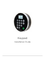
Keypad
Installation Guide

dormakaba USA Inc. | Keypad Installation Guide 7033.0322 Rev D 07/22 2
Table of Contents
INTRODUCTION ................................................................................................................................................................... 2
MOUNT A TAMPER EVIDENT KEYPAD (STANDARD & LOW PROFILE) .................................................................. 3
MOUNT A STANDARD PROFILE SERVICEABLE KEYPAD .......................................................................................... 4
MOUNT A LOW PROFILE SERVICEABLE KEYPAD ...................................................................................................... 6
CONNECT A SAFE LOCK TO A KEYPAD ........................................................................................................................ 7
BATTERY ACCESS & INSTALLATION .............................................................................................................................. 8
STANDARD PROFILE (TAMPER EVIDENT) KEYPAD ...................................................................................................................... 8
STANDARD PROFILE SERVICEABLE KEYPAD ................................................................................................................................ 8
LOW PROFILE KEYPAD ................................................................................................................................................................ 9
SPECIFICATIONS .............................................................................................................................................................. 10
Introduction
The La Gard 700 series Keypads are available in the following variations:
• Standard Profile (Tamper Evident)
• Low Profile (Tamper Evident)
• Standard Profile (Serviceable)
• Low Profile (Serviceable).
Mount the Keypad and connect to a compatible 700 series lock before installing battery or AC power.
• Tamper Evident Standard Profile Keypads are powered by 2 9-volt batteries which are accessible via the
removeable battery tray.
• Serviceable Standard Profile Keypads are powered by 2 9-volt batteries which are accessible by
removing the front of the keypad itself.
• Low Profile Keypads must be installed with a secondary battery box or AC Power Adapter.

dormakaba USA Inc. | Keypad Installation Guide 7033.0322 Rev D 07/22 3
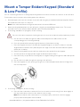
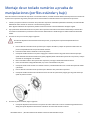
Mount a Tamper Evident Keypad (Standard
& Low Profile)
Prior to connecting a safe lock to a Keypad, the Keypad must first be mounted to the exterior of the safe door.
Follow these steps to properly mount a Keypad to the safe door:
1. Drill and tap the holes into the outside of the safe wall using the provided drill and tap template. Deburr
the middle hole with a file or rotary tool.
Note: Some safe manufacturers might include these holes at the OEM level.
2. Attach the Keypad baseplate onto the safe door using the provided Phillips head screws. The screws
provided come in two variants: Metric M4-07 or US Customary Unit #8-32.
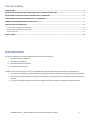
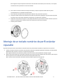
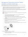
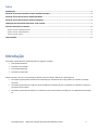
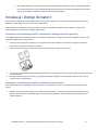
3. If mounting a deadbolt or springbolt, do the following:
Do not use the anti-rotate device during this process, as it will render the safe permanently locked.
a. Run the safe lock cable through the cable holder and place the cable holder over the
corresponding posts of the Keypad body
b. Press the spindle all the way through the bottom of the plastic housing
c. Place the Keypad on the door. Rotate the Keypad 25 degrees clockwise so that it is vertically
aligned. Measure 0.354 inches (9.0 mm) past the edge of the safe door and mark the spindle
with a pen or marker.
d. Remove the Keypad from the safe door and remove the spindle from the Keypad
e. Cut the spindle to the appropriate length as determined from Step c
f. Place the newly cut spindle into the Keypad, once again feeding it through the cable and spindle
holder
g. Run the safe lock cable through the opening in the safe door
h. Place the Keypad over the opening in the grooves of the baseplate and rotate it 25 degrees to
the vertical position
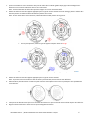
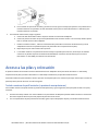
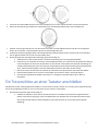
4. If mounting a swingbolt, do the following:
a. Place the anti-rotate device inside the four-hole locations in the housing. Press down lightly so
the anti-rotate device sinks into the channel in the housing
Note: Ensure that the anti-rotate device is oriented properly, otherwise it will not engage
properly with the baseplate when installed.

dormakaba USA Inc. | Keypad Installation Guide 7033.0322 Rev D 07/22 4
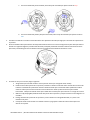
b. Run the cable through the opening in the cable holder and place the cable holder over the
corresponding posts in the Keypad body
c. Run the safe lock cable through the opening in the safe door
d. Place the Keypad over the opening in the channel of the baseplate and rotate 25 degrees to the
vertical position. Some resistance occurs when winding up the anti-rotate device
e. The anti-rotate device will click into place, permanently locking the Keypad into a vertical
position; the Keypad cannot be removed from the safe door without damaging the Keypad
f. Install the swingbolt
Mount a Standard Profile Serviceable
Keypad
Follow these steps to properly mount a Standard Profile Serviceable Keypad to the safe door:
1. Drill and tap the holes into the outside of the safe wall using the provided drill and tap template. Deburr
the middle hole with a file or rotary tool.
Note: Some safe manufacturers might include these holes at the OEM level.
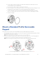
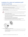
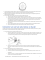
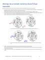
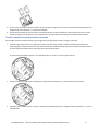
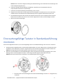
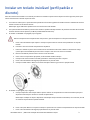
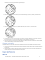
2. Mount the baseplate using the proper retainers for the desired lock type. Prior to mounting, align the
baseplate in the correct position using the reference arrow pointing to the top.
Note: If you are using horizontal holes, then the reference arrow should be pointing to the left.
a. For the Swingbolt application, use the retainer type shown above in Red.

dormakaba USA Inc. | Keypad Installation Guide 7033.0322 Rev D 07/22 5
b. For the Deadbolt and Springbolt application, use the retainer type shown above in Blue.
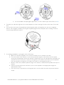
3. Feed the lock cable through the hole in the baseplate so that it emerges from the other side of the safe
door.
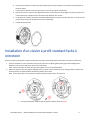
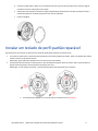
4. Line up divot on bottom of keypad body with triangular mark on baseplate (see arrows on diagram
below). Once aligned, install by pressing the keypad up against the baseplate, then rotating clockwise
until the keypad latches in place.
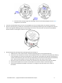
5. If installing a deadbolt or springbolt, do the following:
a. Make sure that the keypad is in its vertical orientation (not rotated to the side).
b. From the inside of the safe door, insert the spindle through the central hole into the square
opening in the baseplate. Orient the spindle so that the groove in the spindle faces upward if you
used the vertical screw holes or faces to the right if you used the horizontal screw hole pattern.
Place the spindle such that the lock cable runs inside of or alongside the groove.
c. Measure .354 inches (9.0mm) past the edge of the safe door and mark the spindle with a pen or
marker.
d. Remove the spindle from the safe door, then cut the spindle to the appropriate length as
determined in step c.
e. Place the newly cut spindle into the keypad, then route the cable the same way as described in
step b.

dormakaba USA Inc. | Keypad Installation Guide 7033.0322 Rev D 07/22 6
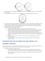
Mount a Low Profile Serviceable Keypad
Follow these steps to properly mount a Low Profile Keypad to the safe door:
1. Drill and tap the holes into the outside of the safe wall using the provided drill and tap template. Deburr
the middle hole with a file or rotary tool.
Note: Some safe manufacturers might include these holes at the OEM level.
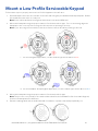
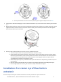
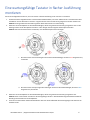
2. Mount the baseplate using the proper retainers for the desired lock type. Prior to mounting, align the
baseplate in the correct position using the reference arrow pointing to the top.
Note: If you are using horizontal holes, then the reference arrow should be pointing to the left.
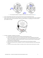
c. For the Swingbolt application, use the retainer type shown above in Red.
d. For the Deadbolt and Springbolt application, use the retainer type shown above in Blue.
3. Mount the baseplate using the proper retainers for the desired lock type.
Note: This process is very similar to the method described for the Standard Profile Serviceable Keypad,
however the baseplates are different.
4. Release retaining latch with a small flat blade screwdriver or plastic shim and pull partially out.

dormakaba USA Inc. | Keypad Installation Guide 7033.0322 Rev D 07/22 7
5. Feed the keypad cable through the hole in the baseplate so that it emerges from the other side of the safe
door.
6. Line up divot on bottom of keypad body with triangular mark on baseplate.
7. Once aligned, install by pressing the keypad up against the baseplate, then rotating clockwise until the
keypad latches in place. At this point, it should be vertically aligned.
8. Push retaining latch back into the housing port to hold the keypad in place and prevent it from rotating
and falling off the safe door.
9. If installing a deadbolt or springbolt, do the following:
a. Make sure that the keypad is in its vertical orientation (not rotated to the side).
b. From the inside of the safe door, insert the spindle through the central hole into the square
opening in the baseplate. Orient the spindle so that the groove in the spindle faces upward if you
used the vertical screw holes or faces to the right if you used the horizontal screw hole pattern.
Place the spindle such that the lock cable runs inside of or alongside the groove.
c. Measure .354 inches (9.0mm) past the edge of the safe door and mark the spindle with a pen or
marker.
d. Remove the spindle from the safe door, then cut the spindle to the appropriate length as
determined in step c.
e. Place the newly cut spindle into the keypad, then route the cable the same way as described in
step b.
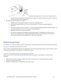
Connect a Safe Lock to a Keypad
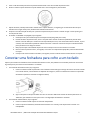
Once the Keypad and safe lock(s) are physically installed onto the safe, they can be connected to form a
System. Follow these steps to connect a safe lock to a Keypad:
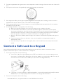
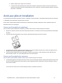
1. For single lock Systems, do the following:
a. Connect the cable from the Keypad into the ENT port. With the lock connected, apply power to
the system. If a Battery Box, Alarm Box or AC power adapter is used, plug the cable from any of
those accessories into the safe lock BAT port (as shown in the diagram below)
b. Follow the on-screen prompts for Display Keypads or consult the System User Guide (Document
#7040.1121) for non-Display Keypads to enter the lock settings and initialization
2. For multi-lock Systems, do the following:

dormakaba USA Inc. | Keypad Installation Guide 7033.0322 Rev D 07/22 8
a. Connect the Keypad cable to the port on the side of the Multiplexer
b. Connect the first safe lock (known as Lock #1 to the System) from the ENT port to the #1 input
on the Multiplexer
c. From Lock #1, connect from the BAT port to a power supply (either the AC Adapter into a wall
receptacle or to the BAT port of a Battery Box)
d. Repeat Step b for each safe lock
e. Display Keypads will show prompts on screen to continue, while non-Display Keypads require
pound (#) commands. Consult the System User Guide (Document #7041.0320) for more
information
Battery Access & Installation
The System can be powered multiple ways: AC adapter (see Document #7037.0320), Battery Box (see
Document #7035.0320), and/or battery power from the Keypad.
Only the standard profile Keypad possesses a battery pack for primary power, while a low-profile version uses a
battery backup in case of emergencies.
Standard Profile (Tamper Evident) Keypad
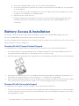
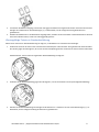
For Standard Profile (Tamper Evident) Keypads, do the following to access and install the batteries:
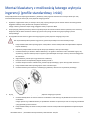
1. Press downward on the spring-loaded button located at the bottom of the keypad’s battery pack. The
spring mechanism will partially eject the battery pack out of the housing.
2. With the battery pack partially removed, grab the tip of the battery pack and remove it from the Keypad.
3. At this point the batteries are free to be added/removed/replaced. When installing the 9V batteries, use
the markers in the battery tray to ensure the proper +/- orientation for each battery.
4. When finished installing the batteries into the battery tray, slide the tray back into the housing unit. When
this is done properly, you should hear a small “click” sound ensuring the tray is secured properly.
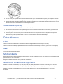
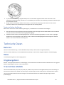
Standard Profile Serviceable Keypad
For standard profile Keypads, do the following to access and install the batteries:
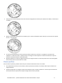
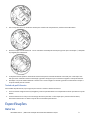
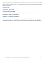
1. First, press the button on the underside of the keypad body. While holding this button, rotate the keypad
counterclockwise until it becomes free from the baseplate. Flip over the keypad so that the reverse side of
the keypad body is visible.

dormakaba USA Inc. | Keypad Installation Guide 7033.0322 Rev D 07/22 9
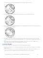
The reverse side of the keypad, with the battery cover in place, appears as follows:
2. Twist the battery cover counterclockwise to detach it from the housing, as shown below:
3. Remove the battery cover and install the batteries. Use the labels in the battery tray to ensure the proper
+/- orientation for each battery.
4. The battery cover can be reinserted the same way that it was removed: by lining up the posts (with the
“this side up” label oriented as pictured) and twisting the cover so that the posts engage with the battery
cover.
5. Replace the body of the keypad back onto the keypad by lining up the divot with the triangle on the
keypad and rotating clockwise until the keypad body stops moving.
Low Profile Keypad
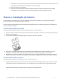
For Low Profile Keypads, do the following to access and install the backup battery:
1. If backup (emergency) power is needed, flip up the battery panel on the lower housing, which will release a
battery strap.
2. Connect the 9V battery to the strap and use that power to get into the safe. After the safe door is
opened, disconnect the 9V battery and fold the strap back into the Low Profile Keypad.

dormakaba USA Inc. | Keypad Installation Guide 7033.0322 Rev D 07/22 10
Specifications
Batteries
Standard Profile Keypad: 2 x 9V DC alkaline batteries (Eveready™ or Duracell™ strongly preferred)
Low Profile Keypad: 1 x 9V DC alkaline batteries (Eveready™ or Duracell™ strongly preferred, for emergency
access)
Relay
12V DC @ 20 mA Max input
Environmental
Operating & Storage Temperature Range: For UL compliance, this product was verified for operation at 32 –
122 °F (0 – 50 °C)
Relative Humidity Range: 0 – 95% non-condensing
Safe Lock Models
Keypad Models 701, 702, 702D, 703, 703B, 704, 704B and 705 (Input Units Keypads) for use with High Security
Lock Models 731 (Deadbolt), 732 (Springbolt), 733 (Swingbolt), and 734 (Redundant Lock).
Keypad Models 7BAS for use with High Security Lock Models 7B1 (Deadbolt) and 7B3 (Swingbolt).

Clavier
Guide d'installation

dormakaba USA Inc. | Guide d’installation des claviers 7033.0322 Rév. D 07/22 2
Table des matières
INTRODUCTION ............................................................................................................................................................................. 2
INSTALLATION D’UN CLAVIER ANTI-VANDALISME (PROFIL STANDARD ET PROFIL BAS) ................................................................... 3
INSTALLATION D’UN CLAVIER A PROFIL STANDARD FACILE A ENTRETENIR ..................................................................................... 4
INSTALLATION D’UN CLAVIER A PROFIL BAS FACILE A ENTRETENIR ................................................................................................ 5
CONNECTER UNE SERRURE SECURISEE A UN CLAVIER .................................................................................................................... 7
ACCES AUX PILES ET INSTALLATION ............................................................................................................................................... 8
CLAVIER A PROFIL STANDARD (ANTI-VANDALISME) ............................................................................................................................................ 8
CLAVIER A PROFIL STANDARD FACILE A ENTRETENIR ............................................................................................................................................ 8
CLAVIER A PROFIL BAS .................................................................................................................................................................................. 9
SPECIFICATIONS .......................................................................................................................................................................... 10
Introduction
Les claviers La Gard de la série 700 sont disponibles dans les variantes suivantes :
• Profil standard (anti-vandalisme)
• Profil bas (anti-vandalisme)
• Profil standard (facile à entretenir)
• Profil bas (facile à entretenir)
Installez le clavier et connectez-le à une serrure compatible de la série 700 avant d’installer la batterie ou l’alimentation CA.
• Les claviers anti-vandalisme à profil standard sont alimentés par deux piles de 9 volts accessibles par le bac à piles amovible.
• Les claviers à profil standard faciles à entretenir sont alimentés par deux piles de 9 volts accessibles en retirant la face avant
du clavier.
• Les claviers à profil bas doivent être installés avec un boîtier de piles secondaire ou un adaptateur d’alimentation CA.

dormakaba USA Inc. | Guide d’installation des claviers 7033.0322 Rév. D 07/22 3
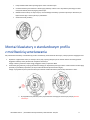
Installation d’un clavier anti-vandalisme (profil
standard et profil bas)
Avant de connecter une serrure sécurisée à un clavier, ce dernier doit être installé à l’extérieur de la porte du coffre-fort. Suivez les
étapes suivantes pour installer correctement un clavier sur la porte du coffre-fort :
1. Percez et taraudez les trous à l’extérieur de la paroi du coffre-fort à l’aide du gabarit de perçage et de taraudage fourni.
Ébavurez le trou central à l’aide d’une lime ou d’un outil rotatif.
Note : Certains fabricants de coffres-forts peuvent intégrer ces trous au niveau des OEM.
2. Fixez le châssis du clavier sur la porte du coffre-fort à l’aide des vis cruciformes fournies. Les vis fournies sont de deux types :
Métrique M4-07 ou US #8-32.
3. Si vous installez un pêne dormant ou un verrou à ressort, procédez comme suit :
N’utilisez pas le dispositif anti-rotation pendant cette opération, car cela verrouillerait définitivement le coffre-fort.
a. Faites passer le câble de la serrure sécurisée dans le porte-câble et placez le porte-câble sur les montants
correspondants du boîtier du clavier.
b. Enfoncez la tige jusqu’au fond du boîtier en plastique.
c. Placez le clavier sur la porte. Faites pivoter le clavier de 25 degrés dans le sens des aiguilles d’une montre afin de
l’aligner verticalement. Mesurez 0,354 pouce (9,0 mm) au-delà du bord de la porte du coffre-fort et marquez la
tige à l’aide d’un stylo ou d’un marqueur.
d. Retirez le clavier de la porte du coffre-fort et retirez la tige du clavier.
e. Coupez la tige à la longueur appropriée, comme indiqué à l’étape c.
f. Placez la tige coupée dans le clavier, en la faisant à nouveau passer par le support de câble et de tige.
g. Faites passer le câble de la serrure sécurisée par l’ouverture de la porte du coffre-fort.
h. Placez le clavier sur l’ouverture des rainures du châssis et faites-le pivoter de 25 degrés en position verticale.
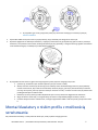
4. Si vous installez un pêne pivotant, procédez comme suit :
a. Placez le dispositif anti-rotation dans les quatre trous du boîtier. Appuyez légèrement pour enfoncer le dispositif
anti-rotation dans le boîtier.
Note : Veillez à ce que le dispositif anti-rotation soit bien positionné, sinon il ne s’enclenchera pas bien dans le
châssis lors de l’installation.

dormakaba USA Inc. | Guide d’installation des claviers 7033.0322 Rév. D 07/22 4
b. Faites passer le câble par l’ouverture du porte-câble et placez le porte-câble sur les montants correspondants du
boîtier du clavier.
c. Faites passer le câble de la serrure sécurisée par l’ouverture de la porte du coffre-fort.
d. Placez le clavier sur l’ouverture de la goulotte du châssis et faites-le pivoter de 25 degrés en position verticale. Une
certaine résistance se produit lors de l’enroulement du dispositif anti-rotation.
e. Le dispositif anti-rotation s’enclenche, verrouillant définitivement le clavier en position verticale ; le clavier ne peut
pas être retiré de la porte du coffre-fort sans être endommagé.
f. Installez le pêne pivotant.
Installation d’un clavier à profil standard facile à
entretenir
Suivez les étapes suivantes pour installer correctement un clavier à profil standard facile à entretenir sur la porte du coffre-fort :
1. Percez et taraudez les trous à l’extérieur de la paroi du coffre-fort à l’aide du gabarit de perçage et de taraudage fourni.
Ébavurez le trou central à l’aide d’une lime ou d’un outil rotatif.
Note : Certains fabricants de coffres-forts peuvent intégrer ces trous au niveau des OEM.
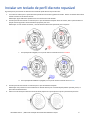
2. Montez le châssis à l’aide des supports appropriés pour le type de serrure souhaité. Avant le montage, placez le châssis dans
la bonne position à l’aide de la flèche de référence pointant vers le haut.
Note : Si vous utilisez des trous horizontaux, la flèche de référence doit pointer vers la gauche.
a. Pour le pêne pivotant, utilisez le type de support indiqué ci-dessus en Rouge.

dormakaba USA Inc. | Guide d’installation des claviers 7033.0322 Rév. D 07/22 5
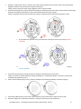
b. Pour le pêne dormant et le verrou à ressort, utilisez le type de support indiqué ci-dessus en Bleu.
3. Faites passer le câble de verrouillage par le trou du châssis de manière à ce qu’il ressorte de l’autre côté de la porte du coffre-
fort.
4. Alignez la fente située sous le clavier avec le repère triangulaire du châssis (voir les flèches sur le schéma ci-dessous). Une fois
l’alignement réalisé, installez le clavier en le pressant contre le châssis, puis en le faisant pivoter dans le sens des aiguilles
d’une montre jusqu’à ce qu’il s’enclenche.
5. Si vous installez un pêne dormant ou un verrou à ressort, procédez comme suit :
a. Assurez-vous que le clavier est en position verticale (non tourné sur le côté).
b. Depuis l’intérieur de la porte du coffre-fort, insérez la tige par le trou central dans l’ouverture carrée du châssis.
Orientez la tige de manière à ce que la rainure pointe vers le haut si vous avez utilisé les trous de vis verticaux ou
vers la droite si vous avez utilisé les trous de vis horizontaux. Placez la tige de manière à ce que le câble de
verrouillage passe à l’intérieur ou le long de la rainure.
c. Mesurez 0,354 pouce (9,0 mm) au-delà du bord de la porte du coffre-fort et marquez la tige à l’aide d’un stylo ou
d’un marqueur.
d. Retirez la tige de la porte du coffre-fort, puis coupez-la à la longueur appropriée, comme indiqué à l’étape c.
e. Placez la tige coupée dans le clavier, puis acheminez le câble, comme décrit à l’étape b.
Installation d’un clavier à profil bas facile à
entretenir
Suivez les étapes suivantes pour installer correctement un clavier à profil bas sur la porte du coffre-fort :

dormakaba USA Inc. | Guide d’installation des claviers 7033.0322 Rév. D 07/22 6
1. Percez et taraudez les trous à l’extérieur de la paroi du coffre-fort à l’aide du gabarit de perçage et de taraudage fourni.
Ébavurez le trou central à l’aide d’une lime ou d’un outil rotatif.
Note : Certains fabricants de coffres-forts peuvent intégrer ces trous au niveau des OEM.
2. Montez le châssis à l’aide des supports appropriés pour le type de serrure souhaité. Avant le montage, placez le châssis dans
la bonne position à l’aide de la flèche de référence pointant vers le haut.
Note : Si vous utilisez des trous horizontaux, la flèche de référence doit pointer vers la gauche.
c. Pour le pêne pivotant, utilisez le type de support indiqué ci-dessus en Rouge.
d. Pour le pêne dormant et le verrou à ressort, utilisez le type de support indiqué ci-dessus en Bleu.
3. Montez le châssis à l’aide des supports appropriés pour le type de serrure souhaité.
Note : Ce processus est très similaire à celui du clavier à profil standard, mais les châssis sont différents.
4. Déverrouillez le pêne de retenue à l’aide d’un petit tournevis à lame plate ou d’une cale en plastique et tirez partiellement
vers l’extérieur.
5. Faites passer le câble du clavier par le trou du châssis de manière à ce qu’il ressorte de l’autre côté de la porte du coffre-fort.
6. Alignez la fente située sous le clavier avec le repère triangulaire du châssis.

dormakaba USA Inc. | Guide d’installation des claviers 7033.0322 Rév. D 07/22 7
7. Une fois l’alignement réalisé, installez le clavier en le pressant contre le châssis, puis en le faisant pivoter dans le sens des
aiguilles d’une montre jusqu’à ce qu’il s’enclenche. Le clavier doit alors être aligné verticalement.
8. Repoussez le pêne de retenue dans l’orifice du boîtier pour maintenir le clavier en place et l’empêcher de pivoter et de
tomber de la porte du coffre-fort.
9. Si vous installez un pêne dormant ou un verrou à ressort, procédez comme suit :
a. Assurez-vous que le clavier est en position verticale (non tourné sur le côté).
b. Depuis l’intérieur de la porte du coffre-fort, insérez la tige par le trou central dans l’ouverture carrée du châssis.
Orientez la tige de manière à ce que la rainure pointe vers le haut si vous avez utilisé les trous de vis verticaux ou
vers la droite si vous avez utilisé les trous de vis horizontaux. Placez la tige de manière à ce que le câble de
verrouillage passe à l’intérieur ou le long de la rainure.
c. Mesurez 0,354 pouce (9,0 mm) au-delà du bord de la porte du coffre-fort et marquez la tige à l’aide d’un stylo ou
d’un marqueur.
d. Retirez la tige de la porte du coffre-fort, puis coupez-la à la longueur appropriée, comme indiqué à l’étape c.
e. Placez la tige coupée dans le clavier, puis acheminez le câble, comme décrit à l’étape b.
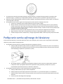
Connecter une serrure sécurisée à un clavier
Une fois le clavier et la (les) serrure(s) sécurisée(s) installés sur le coffre-fort, ils peuvent être connectés pour former un système.
Pour connecter une serrure sécurisée à un clavier, procédez comme suit :
1. Pour les systèmes à serrure unique, procédez comme suit :
a. Connectez le câble du clavier au port ENT. Une fois la serrure connectée, mettez le système sous tension. Si vous
utilisez un boîtier de piles, un boîtier d’alarme ou un adaptateur d’alimentation CA, branchez le câble de l’un de
ces accessoires dans le port BAT de la serrure sécurisée (comme indiqué sur le schéma ci-dessous).
b. Suivez les instructions à l’écran pour les claviers avec écran ou consultez le Guide d’utilisation du système
(document n° 7040.1121) pour les claviers sans écran afin de procéder aux paramétrages et à l’initialisation de la
serrure.
2. Pour les systèmes à plusieurs serrures, procédez comme suit :
a. Connectez le câble du clavier au port situé sur le côté du multiplexeur.
b. Connectez la première serrure sécurisée (appelée serrure n°1 dans le système) du port ENT à l’entrée n°1 du
multiplexeur.
c. À partir de la serrure n° 1, connectez le port BAT à une source d’alimentation (soit l’adaptateur CA dans une prise
murale, soit le port BAT d’un boîtier de piles).

dormakaba USA Inc. | Guide d’installation des claviers 7033.0322 Rév. D 07/22 8
d. Répétez l’étape b pour chaque serrure sécurisée
e. Les claviers avec écran afficheront des invites pour continuer, tandis que les claviers sans écran nécessiteront la
saisie de commandes à l’aide de la touche dièse (#). Pour en savoir plus, consultez le Guide d’utilisation du système
(document n° 7041.0320).
Accès aux piles et installation
Le système peut être alimenté de plusieurs manières : Adaptateur CA (voir document n° 7037.0320), boîtier de piles (voir document
n° 7035.0320), et/ou alimentation par piles à partir du clavier.
Seul le clavier à profil standard possède une batterie pour l’alimentation principale, tandis que la version à profil bas utilise une
batterie de secours en cas d’urgence.
Clavier à profil standard (anti-vandalisme)
Pour les claviers à profil standard (anti-vandalisme), procédez comme suit pour accéder aux piles et les installer :
1. Appuyez sur le bouton à ressort situé au bas du bloc-piles du clavier. Le mécanisme à ressort éjecte partiellement le bloc-piles
du boîtier.
2. Une fois le bloc-piles partiellement retiré, saisissez l’extrémité du bloc-piles et retirez-le du clavier.
3. Les piles peuvent alors être ajoutées/retirées/remplacées. Lors de l’installation des piles de 9 V, utilisez les repères du bac à
piles pour vous assurer de respecter le sens +/- de chaque pile.
4. Une fois les piles installées dans le bac, faites glisser ce dernier dans le boîtier. Si cette opération est bien effectuée, vous
devez entendre un petit « clic » qui indique que le bac est correctement fixé.
Clavier à profil standard facile à entretenir
Pour les claviers à profil standard, procédez comme suit pour accéder aux piles et les installer :
1. Tout d’abord, appuyez sur le bouton situé sous le clavier. Tout en maintenant ce bouton enfoncé, faites pivoter le clavier dans
le sens inverse des aiguilles d’une montre jusqu’à ce qu’il se détache du châssis. Retournez le clavier de manière à ce que la
face arrière soit visible.
La face arrière du clavier, avec le couvercle des piles en place, se présente comme suit :

dormakaba USA Inc. | Guide d’installation des claviers 7033.0322 Rév. D 07/22 9
2. Faites pivoter le couvercle des piles dans le sens inverse des aiguilles d’une montre pour le détacher du boîtier, comme illustré
ci-dessous :
3. Retirez le couvercle du compartiment et installez les piles. Utilisez les étiquettes du bac à piles pour vous assurer de respecter
le sens +/- de chaque pile.
4. Le couvercle des piles peut être remis en place de la même manière qu’il a été retiré : en alignant les montants (avec
l’étiquette « ce côté vers le haut » orientée comme sur l’image) et en faisant pivoter le couvercle de manière à ce que les
montants s’enclenchent dans le couvercle des piles.
5. Replacez le boîtier sur le clavier en alignant la fente sur le triangle du clavier et en le faisant pivoter dans le sens des aiguilles
d’une montre jusqu’à ce que le boîtier soit stable.
Clavier à profil bas
Pour les claviers à profil bas, procédez comme suit pour accéder à la batterie de secours et l’installer :
1. Si une alimentation de secours est nécessaire, relevez le panneau de la batterie sur le boîtier inférieur pour accéder à une
sangle de batterie.
2. Connectez la pile de 9 V à la sangle et utilisez cette alimentation pour accéder au coffre-fort. Une fois la porte du coffre-fort
ouverte, déconnectez la pile de 9 V et repliez la sangle dans le clavier à profil bas.
Strona się ładuje...
Strona się ładuje...
Strona się ładuje...
Strona się ładuje...
Strona się ładuje...
Strona się ładuje...
Strona się ładuje...
Strona się ładuje...
Strona się ładuje...
Strona się ładuje...
Strona się ładuje...
Strona się ładuje...
Strona się ładuje...
Strona się ładuje...
Strona się ładuje...
Strona się ładuje...
Strona się ładuje...
Strona się ładuje...
Strona się ładuje...
Strona się ładuje...
Strona się ładuje...
Strona się ładuje...
Strona się ładuje...
Strona się ładuje...
Strona się ładuje...
Strona się ładuje...
Strona się ładuje...
Strona się ładuje...
Strona się ładuje...
Strona się ładuje...
Strona się ładuje...
Strona się ładuje...
Strona się ładuje...
Strona się ładuje...
Strona się ładuje...
Strona się ładuje...
Strona się ładuje...
Strona się ładuje...
Strona się ładuje...
Strona się ładuje...
Strona się ładuje...
-
 1
1
-
 2
2
-
 3
3
-
 4
4
-
 5
5
-
 6
6
-
 7
7
-
 8
8
-
 9
9
-
 10
10
-
 11
11
-
 12
12
-
 13
13
-
 14
14
-
 15
15
-
 16
16
-
 17
17
-
 18
18
-
 19
19
-
 20
20
-
 21
21
-
 22
22
-
 23
23
-
 24
24
-
 25
25
-
 26
26
-
 27
27
-
 28
28
-
 29
29
-
 30
30
-
 31
31
-
 32
32
-
 33
33
-
 34
34
-
 35
35
-
 36
36
-
 37
37
-
 38
38
-
 39
39
-
 40
40
-
 41
41
-
 42
42
-
 43
43
-
 44
44
-
 45
45
-
 46
46
-
 47
47
-
 48
48
-
 49
49
-
 50
50
-
 51
51
-
 52
52
-
 53
53
-
 54
54
-
 55
55
-
 56
56
-
 57
57
-
 58
58
-
 59
59
-
 60
60
-
 61
61


Dormakaba LA GARD 700 Series Instrukcja instalacji
- Typ
- Instrukcja instalacji
w innych językach
Powiązane artykuły
Inne dokumenty
-
Dormakaba LA GARD 700 Series Battery Box Instrukcja instalacji
-
-
-
FORCLOVER CJW-PG6473 Instrukcja obsługi
-
Kaba LA GARD 700 Series Instrukcja instalacji
-
CTA ADD-USBPOSB Instrukcja obsługi
-
SentrySafe SFW205TWC instrukcja
-
Risco ProSYS KPP Instrukcja instalacji
-
Perel BG90014 Instrukcja obsługi
-
Perel BG90018 Instrukcja obsługi