AAT NVIP-5DN3512V/IR-1P Instrukcja obsługi
- Kategoria
- Kamery ochrony
- Typ
- Instrukcja obsługi

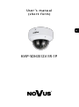
U s e r ’s m a n u a l
(s h o rt form )
NVIP-5DN3512V/IR-1P

NVIP-5DN3512V/IR-1P - User’s manual (short form) ver 1.1.
All rights reserved © AAT Holding S.A.
2
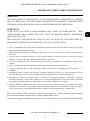
IMPORTANT SAFEGUARDS AND WARNINGS
EMC (2004/108/EC) and LVD (2006/95/EC ) Directives
CE Marking
Our products are manufactured to comply with requirements of the following directives and national regulations
implementing the directives:
Electromagnetic compatibility EMC 2004/108/EC.
Low voltage LVD 2006/95/EC with further amendment. The Directive applies to electrical
equipment designed for use with a voltage rating of between 50VAC and 1000VAC as well as
75VDC and 1500VDC.
WEEE Directive 2012/19/EU
Information on Disposal for Users of Waste Electrical and Electronic Equipment
This appliance is marked according to the European 1000VAC Directive on Waste Electrical and
Electronic Equipment (2012/19/EU) and further amendments. By ensuring this product is disposed of correctly,
you will help to prevent potential negative consequences for the environment and human health, which could
otherwise be caused by inappropriate waste handling of this product.
The symbol on the product, or the documents accompanying the product, indicates that this appliance may not be
treated as household waste. It shall be handed over to the applicable collection point for used up electrical and
electronic equipment for recycling purpose. For more information about recycling of this product, please contact
your local authorities, your household waste disposal service or the shop where you purchased the product.
RoHS Directive 2011/65/EU
Out of concern for human health protection and friendly environment, we assure that our products
falling under RoHS Directive regulations, regarding the restriction of the use of hazardous
substances in electrical and electronic equipment, have been designed and manufactured in
compliance with the above mentioned regulations. Simultaneously, we claim that our products have
been tested and do not contain hazardous substances whose exceeding limits could have negative
impact on human health or natural environment
Information
The device, as a part of professional CCTV system used for surveillance and control, is not designed for self
installation in households by individuals without technical knowledge.
Excluding of responsibility in case of damaging data on a disk or other devices:
The manufacturer does not bear any responsibility in case of damaging or losing data on a disk or other devices
during device operation.
WARNING!
PRIOR TO UNDERTAKING ANY ACTION THAT IS NOT DESCRIBED FOR THE GIVEN PRODUCT IN
USER’S MANUAL AND OTHER DOCUMENTS DELIVERED WITH THE PRODUCT, OR IF IT DOES
NOT ARISE FROM THE USUAL APPLICATION OF THE PRODUCT, MANUFACTURER MUST BE
CONTACTED UNDER THE RIGOR OF EXCLUDING THE MANUFACTURER’S RESPONSIBILITY FOR
THE RESULTS OF SUCH AN ACTION.

NVIP-5DN3512V/IR-1P - User’s manual (short form) ver 1.1.
All rights reserved © AAT Holding S.A.
3
IMPORTANT SAFEGUARDS AND WARNINGS
WARNING!
THE KNOWLEDGE OF THIS MANUAL IS AN INDESPENSIBLE CONDITION OF A PROPER
DEVICE OPERATION. YOU ARE KINDLY REQUSTED TO FAMILIRIZE YOURSELF WITH
THE MANUAL PRIOR TO INSTALLATION AND FURTHER DEVICE OPERATION.
WARNING!
USER IS NOT ALLOWED TO DISASSEMBLE THE CASING AS THERE ARE NO USER
-SERVICEABLE PARTS INSIDE THIS UNIT. ONLY AUTHORIZED SERVICE PERSONNEL
MAY OPEN THE UNIT
INSTALLATION AND SERVICING SHOULD ONLY BE DONE BY QUALIFIED SERVICE
PERSONNEL AND SHOULD CONFORM TO ALL LOCAL REGULATIONS
1. Prior to undertaking any action please consult the following manual and read all the safety and operating
instructions before starting the device.
2. Please keep this manual for the lifespan of the device in case referring to the contents of this manual is
necessary;
3. All the safety precautions referred to in this manual should be strictly followed, as they have a direct
influence on user’s safety and durability and reliability of the device;
4. All actions conducted by the servicemen and users must be accomplished in accordance with the user’s
manual;
5. The device should be disconnected from power sources during maintenance procedures;
6. Usage of additional devices and components neither provided nor recommended by the producer is
forbidden;
7. Mounting the device in places where proper ventilation cannot be provided (e. g. closed lockers etc.) is not
recommended since it may lead to heat build-up and damaging the device itself as a consequence;
8. Mounting the camera on unstable surface or using not recommended mounts is forbidden. Improperly
mounted camera may cause a fatal accident or may be seriously damaged itself. The camera must be mounted
by qualified personnel with proper authorization, in accordance with this user’s manual.
9. Device should be supplied only from a power sources whose parameters are in accordance with those
specified by the producer in the camera technical datasheet. Therefore, it is forbidden to supply the camera
from a power sources with unknown parameters, unstable or not meeting producer’s requirements;
Due to the product being constantly enhanced and optimized, certain parameters and functions
described in the manual in question may change without further notice.
We strongly suggest visiting the www.novuscctv.com website in order to access the newest full manual

NVIP-5DN3512V/IR-1P - User’s manual (short form) ver 1.1.
All rights reserved © AAT Holding S.A.
4
TABLE OF CONTENTS ..................................................................................................... 4
1. FOREWORD INFORMATION ................................................................................... ..5
1.1. General characteristics ......................................................................................... 5
1.2. Technical specification .................................................................................... ...6
1.3. Camera dimension ........................................................................................... ...7
1.4. Package contents ............................................................................................... ...7
2. START-UP AND INITIAL IP CAMERA CONFIGURATION ................................. 8
2.1. Description of connectors and control tools ........................................................ 8
2.2. Zoom and focus adjustment ................................................................................. 9
2.3. Connecting ethernet cable ................................................................................. 10
2.4. Cameras mounting ............................................................................................. 10
2.5. Starting the IP camera ........................................................................................ 11
2.6. Initial configuration via the web browser .......................................................... 12
3. NETWORK CONNECTION UTILIZING WEB BROSWER ................................ 13
3.1. Recommended PC specification for web browser ............................................. 13
3.2. Connection with IP camera via web browser ..................................................... 13
4. USING AND CONFIGURING ..................................................................................... 15
4.1. Displaying live pictures. ..................................................................................... 15
5. ELECTRIC CONNECTORS AND ACCESORIES ................................................. 16
5.1. Connecting power supply to the camera. .......................................................... 16
5.2. Connecting alarm input and output .................................................................... 16
5.3. SD card installation ........................................................................................... 17
6. RESTORING FACTORY DEFAULTS ..................................................................... 18
6.1. Restoring software factory defaults via web browser ........................................ 18
6.2. Restoring software factory defaults via NMSiptool ........................................... 18
6.3. Restoring hardware factory defaults in IP cameras ........................................... 19
TABLE OF CONTENTS

NVIP-5DN3512V/IR-1P - User’s manual (short form) ver 1.1.
All rights reserved © AAT Holding S.A.
5
1. FOREWORD INFORMATION
1.1. General Characteristics
Imager resolution: 5 megapixels
Mechanical IR cut filter ,IR operation capability
Min. Illumination from 0 lx with IR LED on
Wide Dynamic Range (WDR) for enhanced image quality in diverse light conditions
Digital Noise Reduction (DNR)
Lens type: varifocal, f=3.6 ~ 10 mm/F=1.5
Built-in LED illuminator: 30 pcs LED
Alarm input and output
Compression: H.265, H.264, MJPEG
Max video processing resolution: 2592 x 1944
Multi streaming: compression, resolution, speed and quality defined individually for each video
stream
RTP/RTSP protocol support for video transmission
Post-alarm functions
Hardware motion detection
Built-in webserver: camera configuration through the website
MicroSD/SDHC card support
Wide range of responses to alarm events: e-mail with attachment, saving file on FTP server
and triggering alarm output, saving file on SD/SDHC card
Software: NMS (NOVUS MANAGEMENT SYSTEM) for video recording, live monitoring,
playback and remote IP devices administration
Power supply: 12VDC, PoE (Power over Ethernet)
FOREWORD INFORMATION

NVIP-5DN3512V/IR-1P - User’s manual (short form) ver 1.1.
All rights reserved © AAT Holding S.A.
6
1.2. Technical specification
FOREWORD INFORMATION
Image
Image Sensor 5 MPX CMOS sensor 1/1.8”,OV
Number of Effective Pixels 2592 (H) x 1944 (V)
Min. Illumination
0.016 lx/F1.5 - color mode,
0 lx (IR on) - B/W mode
Electronic Shutter auto: 1/25 s ~ 1/100000 s
Wide Dynamic Range (WDR) yes
Digital Noise Reduction (DNR) 2D, 3D
Defog Function (F-DNR) no
Lens
Lens Type varifocal, f=3.6 ~ 10 mm/F1.5
Angle of View (H) 83.7° ~ 36.7°
Day/Night
Switching Type mechanical IR cut filter
Switching Mode auto, manual, time, light sensor
Switching Level Adjustment yes
Switching Schedule yes
Visible Light Sensor yes
Network
Stream Resolution
2592 x 1944, 2560 x 1440 (QHD), 1920 x 1080 (Full HD), 1280 x 720 (HD), 720 x 576 (D1),
352 x 288 (CIF)
Frame Rate 30 fps for 2592 x 1944 and lower resolutions
Multistreaming Mode 3 streams
Video/Audio Compression H.264, H.265, MJPEG/G.711
Number of Simultaneous Connections max. 10
Bandwidth 20 Mb/s in total
Network Protocols Support HTTP, TCP/IP, IPv4, UDP, FTP, DHCP, DDNS, NTP, RTSP, SNMP, PPPoE
ONVIF Protocol Support Profile S (ONVIF 2.3)
Camera Configuration
from Internet Explorer, Firefox, Chrome
languages: Polish, English, Russian, and others
Compatible Software NMS
Other functions
Privacy Zones 4
Motion Detection yes
Region of interest (ROI) 8
Image Processing 90˚ image rotation, 180˚ image rotation, sharpening, mirror effect
Prealarm/Postalarm -/up to 120 s
System Reaction to Alarm Events e-mail with attachment, saving file on FTP server, saving file on SD card
IR LED
LED Number 30
Range 30 m
Interfaces
Video Output BNC, 1.0 Vp-p, 75 Ohm
Audio Input/Output 1 x Jack (3.5 mm)/1 x Jack (3.5 mm)
Alarm Input/Output 1 (NO/NC)/1 relay type
Network Interface 1 x Ethernet - RJ-45 interface, 10/100/1000 Mbit/s
Memory Card Slot microSD
Installation parameters
Dimensions (mm) 150 (Ф) x 114 (H)
Weight 1 kg
Enclosure vandal proof IK10 impact rating aluminium, white poly-carbonate bubble
Power Supply PoE, 12 VDC
Power Consumption
4 W,
6.5 W (IR on)
Operating Temperature -20°C ~ 50°C
Degree of Protection IP 66

NVIP-5DN3512V/IR-1P - User’s manual (short form) ver 1.1.
All rights reserved © AAT Holding S.A.
7
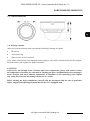
FOREWORD INFORMATION
1.3. Camera dimensions
1.4. Package contents
After you open the package make sure that the following elements are inside:
IP camera
Accessories bag
Short version of user’s manual
If any of this elements has been damaged during transport, pack all the elements back into the original
box and contact your supplier for further assistance.
CAUTION!
If the device was brought from a location with lower temperature, please wait until it reaches
the temperature of location it is currently in. Turning the device on immediately after bringing it
from a location with lower ambient temperature is forbidden, as the condensing water vapour
may cause short-circuits and damage the device as a result.
Before starting the device familiarize yourself with the description and the role of particular
inputs, outputs and adjusting elements that the device is equipped with.

NVIP-5DN3512V/IR-1P - User’s manual (short form) ver 1.1.
All rights reserved © AAT Holding S.A.
8
START-UP AND INITIAL IP CAMERA CONFIGURATION
2.FOREWORD INFORMATION
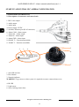
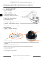
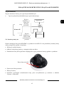
2.1 Description of connectors and control tools
1. BNC video output
2. Audio output
3. Audio input
4. Power supply 12VDC
5. 100 Mb/s Ethernet port (RJ-45 connector)
6. Alarm COM - Alarm output
7. Alarm NO - Alarm output
8. Alarm IN - Alarm input
9. Alarm GND - Alarm input
10. RS485 T+ - Function unavailable
11. RS485 T- - Function unavailable
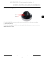
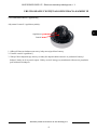
1. microSD card slot
2. Reset button
3. Network indicator
WARNING! To get access to above ports it is required to remove camera dome cover.
4. IR LED
5. Light sensor
6. Screw locking camera base
1
2
4
3
11
6
7
8
9
10
3 2
1
5
6
7
4

NVIP-5DN3512V/IR-1P - User’s manual (short form) ver 1.1.
All rights reserved © AAT Holding S.A.
9
2.2 Zoom and focus adjustment
1. Use the included allen key to remove the camera cover dome screws vand remove cover dome.
2. Adjust zoom and focus.
3. Ensure the rubber gasket inside the camera is properly in place, then mount the camera cover dome
and the camera cover screws.
START-UP AND INITIAL IP CAMERA CONFIGURATION
Zoom
Focus

NVIP-5DN3512V/IR-1P - User’s manual (short form) ver 1.1.
All rights reserved © AAT Holding S.A.
10
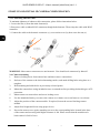
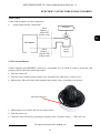
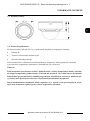
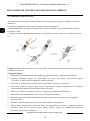
2.3. Connecting ethernet cable
To maintain tightness of ethernet cable connection, please follow instruction below:
1. Loosen the nut (a) from the main element (b).
2. Run power cable (without RJ-45 connector) though both elements. Then crimp the cable with RJ-45
connector.
3. Connect the cable to the hermetic connector (c), screw main cover (b), then screw the nut (a).
WARNING! Other camera connectors are not hermetic. User should seal connectors by himself.
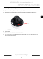
2.4. Camera mounting
1. Remove locking screw from camera base and then remove camera base.
2. Put base of the camera to the desired mounting surface, and mark drilling holes using base as a
template.
3. Drill mounting and cable holes in previously selected points.
4. Mount the camera base using included screws on smooth surface providing declared degree of IP
protection.
5. Mount camera to camera base and screw locking screw.
6. Use the included allen key to remove the camera cover dome screws and remove cover dome.
7. Adjust the position of the camera module. If required, loosen the screws blocking camera
module.
8. Adjust focal length and focus using proper levers.
9. Put on the camera cover again, matching screws to the corresponding holes located in the base
of the camera and screwing until slight resistance is felt. Please ensure that the mask doesn’t
block camera’s field of view.
START-UP AND INITIAL IP CAMERA CONFIGURATION
a
b
a
b
c

NVIP-5DN3512V/IR-1P - User’s manual (short form) ver 1.1.
All rights reserved © AAT Holding S.A.
11
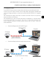
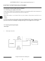
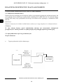
2.5. Starting the IP camera
To run NOVUS IP camera you have to connect ethernet cable between camera and network switch.
To power it up you can connect it directly via power supply adapter with parameters compatible with
camera power supply specification, or camera can be powered with PoE (IEEE 802.3af ) compatible
switch.
After connecting power supply it takes about 30 seconds to start camera. Then You can proceed to
connect to the camera via web browser.
The recommended way to start an IP camera and perform its configuration is a connection directly
to the network switch which is not connected to other devices. To obtain further information about
network configuration parameters (IP address, gateway, network mask, etc.) please contact your
network administrator.
Connection utilising network switch with PoE support
Connection utilising external power supply and network switch
START-UP AND INITIAL CAMERA CONFIGURATION
IP Camera
Network transmission
Network Switch
Computer
Network transmission
Power supply and
network transmission
Computer
IP Camera
Network Switch
PoE
Network transmission

NVIP-5DN3512V/IR-1P - User’s manual (short form) ver 1.1.
All rights reserved © AAT Holding S.A.
12
Connection utilising external power supply directly to the computer
Information:
Power supply adapter is not included. Please use power adapter with parameters specified in user ‘s
manual.
Caution:
In order to provide protection against voltage surges/lightning strikes, usage of appropriate surge
protectors is advised. Any damages resulting from surges are not eligible for service repairs.
2.6. Initial configuration via the web browser
The default network settings for NVIP-5DN3512V/IR-1P IP camera series are :
1. IP address= 192.168.1.200
2. Network mask - 255.255.255.0
3. Gateway - 192.168.1.1
4. User name - root
5. Password - pass
Knowing the camera’s IP address you need to appropriately set PC IP address, so the two devices can
operate in one network subnet ( e.g. for IP 192.168.1.1, appropriate address for the camera ranges from
192.168.1.2 to 192.168.1.254, for example 192.168.1.60). It is not allowed to set the same addresses for
camera and PC computer
You can either set a network configuration (IP address, gateway, net mask, etc.) of NOVUS IP camera
yourself or select DHCP mode (DHCP server is required in this method in target network) by using
web browser or by NMS software. When you use DHCP server check IP address lease and its linking
with camera MAC address to avoid changing or losing IP address during device operation or network/
DHCP server breakdown. You have to remember to use a new camera IP address after changing
network parameters.
After network setting configuration has been done, the camera can be connected to a target network.
START-UP AND INITIAL CAMERA CONFIGURATION
IP Camera
Network transmission - cross over cable
Computer

NVIP-5DN3512V/IR-1P - User’s manual (short form) ver 1.1.
All rights reserved © AAT Holding S.A.
13
3. NETWORK CONNECTION UTILIZING WEB BROSWER
3.1. Recommended PC specification for web browser connections
Requirements below apply to connection with an IP camera, assuming smooth image display
in 2592x1944 resolution and 30 fps speed.
1. CPU Intel Core i3 3 GHz or newer
2. RAM Memory min. 4 GB
3. Graphic card NVIDIA GeForce 512 MB or equivalent
4. OS Windows 7 / 8 / 8.1 / 10
5. Network card 10/100/1000 Mb/s
3.2. Connection with IP camera via web browser
You have to enter camera IP address in the address bar. When you connect to the camera, web browser
will download the applet for displaying images from the camera. In Internet Explorer it may be
necessary to accept an ActiveX control. To do this, click the right mouse button on the message, select
"Install Active X control" and then click Install. After successfully SuperClientEx plug in downloading
run and install it on a computer.
NETWORK CONNECTION UTILIZING WEB BROWSER

NVIP-5DN3512V/IR-1P - User’s manual (short form) ver 1.1.
All rights reserved © AAT Holding S.A.
14
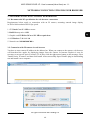
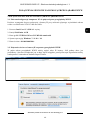
If the installation fails, changing security settings for the IE browser is required. In order to do that,
please choose: Tools > Internet options > Security tab > Custom level and:
Under Download unsigned ActiveX controls - select either Enable or Prompt
Under Initialize and script ActiveX controls not marked as safe - select Enable or Prompt
You can also add the camera’s IP address to “trusted zone” and set lowest security level for it.
In addition, when working in Windows / 7 / 8 / 8.1 / 10 the ActiveX applet may be blocked by
Windows Defender or User account control. In such case you should allow to run this applet, or simply
disable these functions.
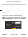
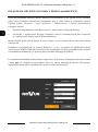
After successful installation login window will be displayed. Default user is root and default password
is pass. For safety reasons, it is recommended to change default user name and password.
WARNING !!! If user forgets login and/or password for IP Camera, it is required to sent
IP Camera back to supplier. In this case, it is not possible for user to restore IP Camera factory
defaults on his own.
NETWORK CONNECTION UTILIZING WEB BROWSER

NVIP-5DN3512V/IR-1P - User’s manual (short form) ver 1.1.
All rights reserved © AAT Holding S.A.
15
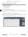
4. USING AND CONFIGURING
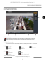
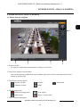
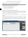
4.1 The Remote Preview Interface
1. Motion detection
Motion detection icon changes color from white to red when motion is detected.
Alarm icon changes color from white to red when alarm situation has occured.
2. Display fluency settings
It is possible to increase video display fluency by setting video buffor (0 ~ 4 seconds).
3. Video size settings
Fix size Zoom in Full screen
Zoom in Zoom out
4. Local record
Start record Snap
Playback Enable / disable audio
5. PTZ - Function unavailable
USING AND CONFIGURING
1
2 3 4
5

NVIP-5DN3512V/IR-1P - User’s manual (short form) ver 1.1.
All rights reserved © AAT Holding S.A.
16
ELECTRIC CONNECTORS AND ACCESORIES
5. ELECTRIC CONNECTORS AND ACCESORIES
5.1. Connecting power supply to the camera.
Camera can be supplied using external power supply unit corresponding with the camera parameters or
by using RJ45 network socket and PoE (802.3af) power supply unit.
Information:
Power supply adapter is not included. Please use power adapter with parameters specified in user’s
manual.
Caution:
In order to provide protection against voltage surges/lightning strikes, usage of appropriate surge
protectors is advised. Any damages resulting from surges are not eligible for service repairs.
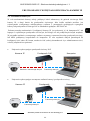
5.2. Connecting alarm inputs/outputs.
Alarm input
Alarm input connection
Alarm
input (-)
Alarm GND
(blue cord)
IP Camera
Alarm
input (+)
Alarm IN
(yellow cord)
Switch/sensor

NVIP-5DN3512V/IR-1P - User’s manual (short form) ver 1.1.
All rights reserved © AAT Holding S.A.
17
ELECTRIC CONNECTORS AND ACCESORIES
Alarm output
Camera alarm output is an relay output type.
Alarm output electric connections
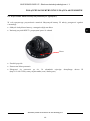
5.3 SD card installation
Camera supports microSD/SDHC cards up to a maximum size of 64GB. In order to install the card
properly, please follow the instructions below:
Turn the camera off
Unscrew screws holding camera dome cover using allen key and remove camera cover.
Mount micro SD card in the socket located at the camera’s base, according to the picture:
Mount camera cover dome and screw to camera base.
Turn the camera on
Check the micro SD card by checking its capacity in the “System Config” -> “SD Card” tab.
Alarm
Output (-)
Alarm COM
(orange cord)
Alarm
Output (+)
Alarm NO
(brown cord)
Indicator
power
supply
Indicator
IP Camera
microSD card slot

NVIP-5DN3512V/IR-1P - User’s manual (short form) ver 1.1.
All rights reserved © AAT Holding S.A.
18
ELECTRIC CONNECTORS AND ACCESORIES
6. RESTORING FACTORY DEFAULTS
Camera allow to restore defaults via:
software (web browser level)
software (NMSiptool level)
Hardware (reset button)
6.1. Restoring factory defaults by software means
User can restore default settings of the IP camera except network settings. To restore to default settings
go to: “Advanced Config -> Config Backup & Restore” tab. Process of restoring takes about two
minutes.
6.2. Restoring factory defaults by software means (NMSiptool level)
NMSip (version 1.23.4 or later) allows to restore factory defaults. To restore settings find camera via
NMSiptool, click right mouse button and choose “ Restore default configuration”. Next, within 30
seconds, it is required to turn the camera power off and on.

NVIP-5DN3512V/IR-1P - User’s manual (short form) ver 1.1.
All rights reserved © AAT Holding S.A.
19
ELECTRIC CONNECTORS AND ACCESORIES
6.3. Restoring factory defaults by hardware means
In order to restore factory defaults for the camera please follow the instructions:
Unscrew two screws holding camera cover dome using allen key and remove camera cover.
Press the RESET button and hold on for 10 seconds
Release button
Mount camera cover dome and screw to camera base.
Log on after approx. 30 seconds using default IP address (http://192.168.1.200) and default user
name (root) and password (pass)
Reset

2016-03-31 JB
AAT Holding S.A., ul. Puławska 431, 02-801 Warszawa, Polska
tel.: 22 546 07 00, faks: 22 546 07 59
www.novuscctv.com
Strona się ładuje...
Strona się ładuje...
Strona się ładuje...
Strona się ładuje...
Strona się ładuje...
Strona się ładuje...
Strona się ładuje...
Strona się ładuje...
Strona się ładuje...
Strona się ładuje...
Strona się ładuje...
Strona się ładuje...
Strona się ładuje...
Strona się ładuje...
Strona się ładuje...
Strona się ładuje...
Strona się ładuje...
Strona się ładuje...
Strona się ładuje...
Strona się ładuje...
-
 1
1
-
 2
2
-
 3
3
-
 4
4
-
 5
5
-
 6
6
-
 7
7
-
 8
8
-
 9
9
-
 10
10
-
 11
11
-
 12
12
-
 13
13
-
 14
14
-
 15
15
-
 16
16
-
 17
17
-
 18
18
-
 19
19
-
 20
20
-
 21
21
-
 22
22
-
 23
23
-
 24
24
-
 25
25
-
 26
26
-
 27
27
-
 28
28
-
 29
29
-
 30
30
-
 31
31
-
 32
32
-
 33
33
-
 34
34
-
 35
35
-
 36
36
-
 37
37
-
 38
38
-
 39
39
-
 40
40


AAT NVIP-5DN3512V/IR-1P Instrukcja obsługi
- Kategoria
- Kamery ochrony
- Typ
- Instrukcja obsługi
w innych językach
- English: AAT NVIP-5DN3512V/IR-1P User manual
Powiązane artykuły
-
Novus NVIP-2H-6401 (NVIP-2DN3030H/IR-1P-II) Instrukcja obsługi
-
-
-
-
-
-
-
-
-