Novus NVIP-5V-6402M/F (NVIP-5DN3615AV/IR-1P/F) Instrukcja obsługi
- Kategoria
- Kamery ochrony
- Typ
- Instrukcja obsługi

Erratum for the user’s manual
Errata instrukcji obsługi
All rights reserved ©/ Wszelkie prawa zastrzeżone ©
AAT Holding S.A., 431 Pulawska St., 02-801 Warsaw, Poland
tel.: +4822 546 07 00, fax: +4822 546 07 59
www.novuscctv.com
NVIP-5V-6402M/F
THE PRODUCT NAME HAS BEEN CHANGED:
OLD NAME: NVIP-5DN3615AV/IR-1P/F
NEW NAME: NVIP-5V-6402M/F
TECHNICAL PARAMETERS HAVE NOT CHANGED
NAZWA PRODUKTU ZOSTAŁA ZMIENIONA:
STARA NAZWA: NVIP-5DN3615AV/IR-1P/F
NOWA NAZWA: NVIP-5V-6402M/F
PARAMETRY TECHNICZNE NIE ULEGŁY ZMIANIE

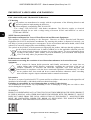
User’s manual
( short fo r m)
NVIP-5DN3615AV/IR-1P/F

NVIP-5DN3615AV/IR-1P/F - User’s manual (short form) ver 1.0
All rights reserved © AAT Holding S.A.
2
IMPORTANT SAFEGUARDS AND WARNINGS
EMC (2014/30/UE) and LVD (2014/35/UE) Directives
CE Marking
Our products are manufactured to comply with the requirements of the following directives and
national regulations implementing the directives:
- Electromagnetic compatibility EMC 2014/30/UE.
- Low voltage LVD 2014/35/EC with further amendment. The Directive applies to electrical
equipment designed for use with a voltage rating of between 50VAC and 1000VAC as well as
75VDC and 1500VDC.
WEEE Directive 2012/19/UE
Information on Disposal for Users of Waste Electrical and Electronic Equipment
This appliance is marked according to the European Directive on Waste Electrical and Electronic
Equipment (2012/19/UE) and further amendments. By ensuring this product is disposed of correctly, you
will help to prevent potential negative consequences for the environment and human health, which could
otherwise be caused by inappropriate waste handling of this product.
The symbol on the product, or the documents accompanying the product, indicates that this appliance may
not be treated as household waste. It shall be handed over to the applicable collection point for
used up electrical and electronic equipment for recycling purpose. For more information about
recycling of this product, please contact your local authorities, your household waste disposal
service or the shop where you purchased the product.
RoHS Directive 2011/65/UE
Information concerning the restriction of use of hazardous substances in electrical electronic
equipment.
Out of concern for human health protection and friendly environment, we assure that our
products falling under RoHS Directive regulations, regarding the restriction of the use of
hazardous substances in electrical and electronic equipment, have been designed and
manufactured in compliance with the above mentioned regulations. Simultaneously, we claim
that our products have been tested and do not contain hazardous substances whose exceeding
limits could have negative impact on human health or natural environment.
Information
The device, as a part of professional CCTV system used for surveillance and control, is not designed for self
installation in households by individuals without technical knowledge.
Excluding of responsibility in case of damaging data on a disk or other devices:
The manufacturer does not bear any responsibility in case of damaging or losing data on a disk or other
devices during device operation.
WARNING!
PRIOR TO UNDERTAKING ANY ACTION THAT IS NOT DESCRIBED FOR THE GIVEN PRODUCT
IN USER’S MANUAL AND OTHER DOCUMENTS DELIVERED WITH THE PRODUCT, OR IF IT
DOES NOT ARISE FROM THE USUAL APPLICATION OF THE PRODUCT, MANUFACTURER
MUST BE CONTACTED UNDER THE RIGOR OF EXCLUDING THE MANUFACTURER’S
RESPONSIBILITY FOR THE RESULTS OF SUCH AN ACTION.

NVIP-5DN3615AV/IR-1P/F - User’s manual (short form) ver 1.0
All rights reserved © AAT Holding S.A.
3
IMPORTANT SAFEGUARDS AND WARNINGS
WARNING!
THE KNOWLEDGE OF THIS MANUAL IS AN INDESPENSIBLE CONDITION OF A PROPER
DEVICE OPERATION. YOU ARE KINDLY REQUSTED TO FAMILIRIZE YOURSELF WITH
THE MANUAL PRIOR TO INSTALLATION AND FURTHER DEVICE OPERATION.
WARNING!
INSTALLATION AND SERVICING SHOULD ONLY BE DONE BY QUALIFIED SERVICE
PERSONNEL AND SHOULD CONFORM TO ALL LOCAL REGULATIONS
1. Prior to undertaking any action please consult the following manual and read all the safety and operating
instructions before starting the device.
2. Please keep this manual for the lifespan of the device in case referring to the contents of this manual is
necessary;
3. All the safety precautions referred to in this manual should be strictly followed, as they have a direct
influence on user’s safety and durability and reliability of the device;
4. All actions conducted by the servicemen and users must be accomplished in accordance with the user’s
manual;
5. The device should be disconnected from power sources during maintenance procedures;
6. Usage of additional devices and components neither provided nor recommended by the producer is
forbidden;
7. You are not allowed to use the camera in high humidity environment (i.e. close to swimming pools, bath tubs,
damp basements);
8. Mounting the device in places where proper ventilation cannot be provided (e. g. closed lockers etc.) is not
recommended since it may lead to heat build-up and damaging the device itself as a consequence;
9. Mounting the camera on unstable surface or using not recommended mounts is forbidden. Improperly
mounted camera may cause a fatal accident or may be seriously damaged itself. The camera must be mounted
by qualified personnel with proper authorization, in accordance with this user’s manual.
10. Device should be supplied only from a power sources whose parameters are in accordance with those
specified by the producer in the camera technical datasheet. Therefore, it is forbidden to supply the camera
from a power sources with unknown parameters, unstable or not meeting producer’s requirements;
Due to the product being constantly enhanced and optimized, certain parameters and functions
described in the manual in question may change without further notice.
We strongly suggest visiting the www.novuscctv.com website in order to access the newest manual.

NVIP-5DN3615AV/IR-1P/F - User’s manual (short form) ver 1.0
All rights reserved © AAT Holding S.A.
4
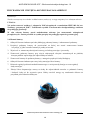
1. FOREWORD INFORMATION
1.1. General Characteristics
Imager resolution: 5.0 megapixels
Mechanical IR cut filter IR operation capability
Min. Illumination from 0 lx with IR LED on
Wide Dynamic Range (WDR) for enhanced image quality in diverse light conditions
Digital Noise Reduction (DNR)
Lens type: motor-zoom, f=2.8-12mm/F1.4
Built-in LED illuminator: 30 LED
Video compression: H.264 / H.265, MJPEG / Audio compression: G711A/G711U
Max video processing resolution: 2592 x 1944
Multi streaming: compression, resolution, speed and quality defined individually for each stream.
Supports up to 3 streams
RTP/RTSP protocol support for video transmission
Up to 3 ROI zones
Memory Micro SD Card Slot up to 128 GB
Audio input/Audio output
BNC output
Alarm Input/Output
Wide range of responses to alarm events: e-mail with attachment, saving file on FTP server
Software: NMS (NOVUS MANAGEMENT SYSTEM) for video recording, live monitoring,
playback and remote IP devices administration
Video Content Analysis (VCA):
Tamper
Abandoned object
Object disappearance
Line cross
Zone entrance
Object counting
Multi loiter
Face detection
Face recognition - advanced analytic function, available only with selected models of the NVR
6000 series.
Power supply: 12VDC, PoE (Power over Ethernet)
TABLE OF CONTENTS

NVIP-5DN3615AV/IR-1P/F - User’s manual (short form) ver 1.0
All rights reserved © AAT Holding S.A.
5
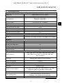
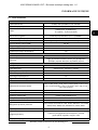
1.2. Technical specification
FOREWORD INFORMATION
IMAGE
Image Sensor 5 MPX CMOS sensor 1/2.5” APTINA
Number of Effecve Pixels 2592 (H) x 1944 (V)
Min. Illuminaon
0.04 lx/F1.4 - color mode ,
0 lx (IR on) - B/W mode
Electronic Shuer auto/manual: 1/3 s ~ 1/100000 s
Digital Slow Shuer (DSS) up to 1/3 s
Wide Dynamic Range (WDR) yes (double scan sensor), 120dB
Digital Noise Reducon (DNR) 2D, 3D
Defog Funcon (F-DNR) yes
Highlight Compensaon (HLC) yes
Back Light Compensaon (BLC) yes
LENS
Lens Type motor-zoom, f=2.8 ~ 12 mm/F1.4
Auto-focus connuous, zoom trigger, day/night mode trigger, manual trigger
DAY/NIGHT
Switching Type mechanical IR cut filter
Switching Mode auto, manual, me
Switching Level Adjustment yes
Switching Delay 2 ~ 120 s
Switching Schedule yes
Visible Light Sensor yes
NETWORK
Stream Resoluon
2592 x 1944, 2592 x 1520, 2560 x 1440 (QHD), 2304 x 1296,
1920 x 1080 (Full HD), 1280 x 720 (HD), 640 x 480 (VGA),
320 x 240 (QVGA)
Frame Rate 30 fps for 2592 x 1944 and lower resoluons
Mulstreaming Mode 3 streams
Video/Audio Compression H.264, H.265, MJPEG/G.711
Number of Simultaneous Connecons max. 6
Bandwidth 60 Mb/s in total
Network Protocols Support
HTTP, TCP/IP, IPv4, IPv4/v6, UDP, HTTPS, Mulcast, FTP, DHCP,
DDNS, RTSP, SNMP, QoS, IEEE 802.1X, PPPoE, SMTP
ONVIF Protocol Support Profile S/G
Camera Configuraon
from Internet Explorer, Chrome browser
languages: Polish, English, Russian, and others
Compable Soware
NMS

NVIP-5DN3615AV/IR-1P/F - User’s manual (short form) ver 1.0
All rights reserved © AAT Holding S.A.
6
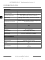
FOREWORD INFORMATION
OTHER FUNCTIONS
Privacy Zones 4
Moon Detecon yes
Region of interest (ROI) 3
Video Content Analysis (VCA)
tamper, abandoned object, object disappearance, line cross, zone en-
trance, object counng, mul loiter, face detecon
Image Processing 180˚ image rotaon, sharpening, mirror effect, corridor mode
Prealarm/Postalarm do 6 s/up to 120 s
System Reacon to Alarm Events
e-mail with aachment, saving file on FTP server, saving file on SD
card, alarm output acvaon
IR LED
LED Number 30
Range 30 m
Angle 90°
INTERFACES
Video Output BNC, 1.0 Vp-p, 75 Ohm
Audio Input/Output 1 x Jack (3.5 mm)/1 x Jack (3.5 mm)
Alarm Input/Output 1 (NO/NC)/1
Network Interface 1 x Ethernet - RJ-45 interface, 10/100 Mbit/s
Memory Card Slot microSD - capacity up to 128GB
INSTALLATION PARAMETERS
Dimensions (mm) 150 (Ф) x 114 (H)
Weight 1 kg
Degree of Protecon IP 66 (details in the user’s manual)
Enclosure
vandalproof IK10 impact rang aluminium, white poly-carbonate bub-
ble
Power Supply PoE, 12 VDC
Power Consumpon
3 W,
8 W (IR on)
Operang Temperature -20°C ~ 50°C

NVIP-5DN3615AV/IR-1P/F - User’s manual (short form) ver 1.0
All rights reserved © AAT Holding S.A.
7
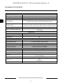
FOREWORD INFORMATION
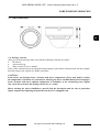
1.3. Camera dimensions
1.4. Package contents
After you open the package make sure that the following elements are inside:
IP camera
Accessories bag
Short version of user’s manual
If any of this elements has been damaged during transport, pack all the elements back into the original
box and contact your supplier for further assistance.
CAUTION!
If the device was brought from a location with lower temperature, please wait until it reaches
the temperature of location it is currently in. Turning the device on immediately after bringing it
from a location with lower ambient temperature is forbidden, as the condensing water vapour
may cause short-circuits and damage the device as a result.
Before starting the device familiarize yourself with the description and the role of particular
inputs, outputs and adjusting elements that the device is equipped with.

NVIP-5DN3615AV/IR-1P/F - User’s manual (short form) ver 1.0
All rights reserved © AAT Holding S.A.
8
1.4. Package contents
After you open the package make sure that the following elements are inside:
IP camera
230 VAC / 12 VDC power supply
Accessories bag
Short version of user’s manual
CD containing manual and software
If any of this elements has been damaged during transport, pack all the elements back into the original
box and contact your supplier for further assistance.
CAUTION!
If the device was brought from a location with lower temperature, please wait until it reaches the
temperature of location it is currently in. Turning the device on immediately after bringing it
from a location with lower ambient temperature is forbidden, as the condensing water vapour
may cause short-circuits and damage the device as a result.
Before starting the device familiarize yourself with the description and the role of particular
inputs, outputs and adjusting elements that the device is equipped with.
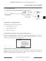
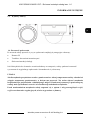
2.START-UP AND INITIAL IP CAMERA CONFIGURATION
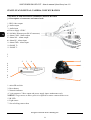
2.1 Description of connectors and control tools
1. BNC video output
2. Audio output
3. Audio input
4. Power supply 12VDC
5. 100 Mb/s Ethernet port (RJ-45 connector)
6. Alarm COM - Alarm output
7. Alarm NO - Alarm output
8. Alarm IN - Alarm input
9. Alarm GND - Alarm input
10. RS485 T+
11. RS485 T-
1. microSD card slot
2. Reset button
3. Network indicator
4. 3 pin connector. Video output and power supply input- maintenance only
NOTICE! To get access to above ports it is required to remove camera dome cover.
5. IR LED
6. Light sensor
7. Screw locking camera base
START-UP AND INITIAL CAMERA CONFIGURATION
1
2
4
3
11
6
7
8
9
10
5
6
7
3 2
1
4

NVIP-5DN3615AV/IR-1P/F - User’s manual (short form) ver 1.0
All rights reserved © AAT Holding S.A.
9
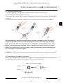
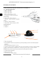
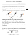
2.3. Connecting ethernet cable
To maintain tightness of ethernet cable connection, please follow instruction below:
1. Loosen the nut (a) from the main element (b).
2. Run power cable (without RJ-45 connector) though both elements. Then crimp the cable with RJ-45
connector.
3. Connect the cable to the hermetic connector (c), screw main cover (b), then screw the nut (a).
The declared degree of protection of the camera relates to its housing and does not take into
account the possibility of moisture infiltration into the interior of the camera by connecting
cables. Connection cables protection through i.e. sealing up is the responsibility of the camera
installer. The manufacturer is not liable for any damages to the camera caused as a result of
failing in performing that activity by installer, which also means that camera damaged in that
way is not subject to warranty repairs
WARNING! 12VDC power connector is not hermetic. User should seal power connector by himself.
2.4. Connecting power supply to the camera.
Camera can be supplied using external power supply unit corresponding with the camera parameters or
by using RJ45 network socket and PoE (802.3at Type 1 ) power supply unit.
START-UP AND INITIAL CAMERA CONFIGURATION
a
b
a
b
c
12 VDC +
12 VDC -
Camera 12 VDC power supply

NVIP-5DN3615AV/IR-1P/F - User’s manual (short form) ver 1.0
All rights reserved © AAT Holding S.A.
10
Information:
Power supply adapter is not included. Please use power adapter with parameters specified in user’s
manual.
Caution:
It is forbidden to use – as the camera power source – PoE equipment (adapters, etc.) not
compatible with IEEE 802.3af standard (items called “passive PoE power supply”). Damages that
results from the usage of improper power supply source are not covered by the warranty
In order to provide protection against voltage surges/lightning strikes, usage of appropriate surge
protectors is advised. Any damages resulting from surges are not eligible for service repairs.
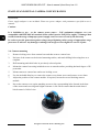
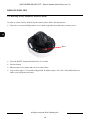
2.4. Camera mounting
1. Remove locking screw from camera base and then remove camera base.
2. Put base of the camera to the desired mounting surface, and mark drilling holes using base as a
template.
3. Drill mounting and cable holes in previously selected points.
4. Mount the camera base using included screws on smooth surface providing declared degree of IP
protection.
5. Mount camera to camera base and screw locking screw.
6. Use the included allen key to remove the camera cover dome screws and remove cover dome.
7. Adjust the position of the camera module. If required, loosen the screws blocking camera
module.
8. Put on the camera cover again, matching screws to the corresponding holes located in the base
of the camera and screwing until slight resistance is felt. Please ensure that the mask doesn’t
block camera’s field of view.
START-UP AND INITIAL CAMERA CONFIGURATION

NVIP-5DN3615AV/IR-1P/F - User’s manual (short form) ver 1.0
All rights reserved © AAT Holding S.A.
11
START-UP AND INITIAL CAMERA CONFIGURATION
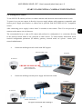
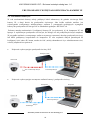
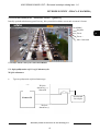
2.5. Starting the IP camera
To run NOVUS IP camera you have to connect ethernet cable between camera and network switch.
To power it up you can connect it directly via power supply adapter with parameters compatible with
camera power supply specification, or camera can be powered with PoE (IEEE 802.3af ) compatible
switch.
After connecting power supply it takes about 30 seconds to start camera. Then You can proceed to
connect to the camera via web browser.
The recommended way to start an IP camera and perform its configuration is a connection directly
to the network switch which is not connected to other devices. To obtain further information about
network configuration parameters (IP address, gateway, network mask, etc.) please contact your
network administrator.
Connection utilising network switch with PoE support
Connection utilising external power supply and network switch
Power supply and
network transmission
Computer
IP Camera
Network Switch PoE
Network transmission
IP Camera
Network transmission
Network Switch
Computer
Network transmission

NVIP-5DN3615AV/IR-1P/F - User’s manual (short form) ver 1.0
All rights reserved © AAT Holding S.A.
12
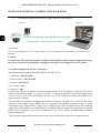
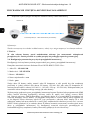
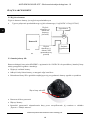
Connection utilising external power supply directly to the computer
Information:
Power supply adapter is not included. Please use power adapter with parameters specified in user ‘s
manual.
Caution:
In order to provide protection against voltage surges/lightning strikes, usage of appropriate surge
protectors is advised. Any damages resulting from surges are not eligible for service repairs.
2.6. Initial configuration via the web browser
The default network settings for NVIP-5DN3615AV/IR-1P/F is:
1. IP address= 192.168.1.200
2. Network mask - 255.255.255.0
3. Gateway - 192.168.1.1
4. User name - root
5. Password - pass
Knowing the camera’s IP address you need to appropriately set PC IP address, so the two devices can
operate in one network subnet ( e.g. for IP 192.168.1.1, appropriate address for the camera ranges from
192.168.1.2 to 192.168.1.254, for example 192.168.1.60). It is not allowed to set the same addresses for
camera and PC computer
You can either set a network configuration (IP address, gateway, net mask, etc.) of NOVUS IP camera
yourself or select DHCP mode (DHCP server is required in this method in target network) by using
web browser or by NMS software. When you use DHCP server check IP address lease and its linking
with camera MAC address to avoid changing or losing IP address during device operation or network/
DHCP server breakdown. You have to remember to use a new camera IP address after changing
network parameters.
After network setting configuration has been done, the camera can be connected to a target network.
START-UP AND INITIAL CAMERA CONFIGURATION
Transmisja danych - kabel ethernetowy skrosowany
Kamera IP
Komputer

NVIP-5DN3615AV/IR-1P/F - User’s manual (short form) ver 1.0
All rights reserved © AAT Holding S.A.
13
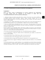
2.7. Security recommendations for network architecture and configuration
WARNING!
Below are shown security recommendations for network architecture and configuration
of CCTV systems that are connected to the Internet to reduce the risk
of unauthorized interference with the system by a third party.
1. Absolutely change the default passwords and user names (if the device gives this possibility) of
all applied network devices (recorders, cameras, routers, network switches, etc.) to the
severely complexity password. Use lowercase and uppercase letters, numbers, and special characters
if there is such possibility.
2. Depending on the available functionality in the order to restrict access to the used network devices at
the administrator account level, it is recommended to configure the users accounts accordingly.
3. Do not use DMZ function (Demilitarized zone) in your router. Using that function you open the
access to recorder system from the Internet on all ports, which gives possibility for an unauthorized
interference with the system.
Instead of DMZ use port forwarding redirect only the ports which are necessary for the performance
of the connection (detailed information about ports of communication in different models of recorders,
cameras, etc. can be found in the operating instructions).
4. Use routers with firewall function and make sure it is enabled and properly configured.
5. It is recommended to change the default network communication port numbers of used devices
if there is such possibility.
6. If used network devices has a UPnP feature and it is not used, turn it off.
7. If used network devices has a P2P feature and it is not used, turn it off.
8. If used network devices support HTTPS protocol for connection, it is recommended to use it.
9. If used network devices support IP filtering for authorized connections function, it is recommended
to use it.
10. If used recorder has two network interfaces it is recommended to use both of them to physically
separate network for cameras and network for Internet connection. The only device in the system,
accessible from Internet will be recorder - there will be no physically access directly to any camera.
START-UP AND INITIAL CAMERA CONFIGURATION

NVIP-5DN3615AV/IR-1P/F - User’s manual (short form) ver 1.0
All rights reserved © AAT Holding S.A.
14
3. NETWORK CONNECTION UTILIZING WEB BROSWER
3.1. Recommended PC specification for web browser connections
Requirements below apply to connection with an IP camera, assuming smooth image display in
2592 x 1944 resolution and 25 fps speed.
1. CPU Intel Core i3 3 GHz or newer
2. RAM Memory min. 4 GB
3. VGA card (any displaying Direct 3D with min. 128 MB RAM memory)
4. OS Windows 7/8/8.1/10
5. Network card 100/1000 Mb/s
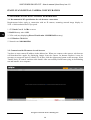
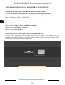
3.2. Connection with IP camera via web browser
You have to enter camera IP address in the address bar. When you connect to the camera, web browser
will download the applet for displaying images from the camera. In Internet Explorer it may be
necessary to accept an ActiveX control. To do this, click the right mouse button on the message, select
"Install Active X control" and then click Install. After successfully NetIPCamera plug in downloading
run and install it on a computer.
START-UP AND INITIAL CAMERA CONFIGURATION

NVIP-5DN3615AV/IR-1P/F - User’s manual (short form) ver 1.0
All rights reserved © AAT Holding S.A.
15
If the installation fails, changing security settings for the IE browser is required. In order to do that,
please choose: Tools > Internet options > Security tab > Custom level and:
Under Download unsigned ActiveX controls - select either Enable or Prompt
Under Initialize and script ActiveX controls not marked as safe - select Enable or Prompt
You can also add the camera’s IP address to “trusted zone” and set lowest security level for it.
In addition, when working in Windows Vista/7 the ActiveX applet may be blocked by Windows
Defender or User account control. In such case you should allow to run this applet, or simply disable
these functions.
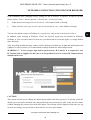
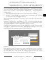
After successful installation login window will be displayed. Default user is root and default password
is pass. For safety reasons, it is recommended to change default user name and password.
WARNING !!! If user forgets login and/or password for IP Camera, it is required to sent
IP Camera back to supplier. In this case, it is not possible for user to restore IP Camera factory
defaults on his own.
CAUTION!
The camera will ask you to change the default password the first time you log in. To do this, check the
Modify password option and then enter and confirm the new password. In order to log into the camera
without changing the password, press the OK button. The message will be displayed each time you log
in, until you change your password or check the Do not show again option.
NETWORK CONNECTION UTILIZING WEB BROWSER

NVIP-5DN3615AV/IR-1P/F - User’s manual (short form) ver 1.0
All rights reserved © AAT Holding S.A.
16
NETWORK CONNECTION UTILIZING WEB BROWSER
4. USING AND CONFIGURING
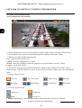
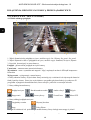
4.1 The Remote Preview Interface
1. Choose stream for live preview from following options: Main stream, Sub stream Third stream.
2. Choose fluent of live preview form following options: Balanced, Real-time, Fluent.
3. Buttons to navigate trough camera options:
Live - main menu for live preview
Config - advanced configuration of camera
Search - menu for searching records and snapshots saved on SD card or local PC Client.
Logout - logout from camera
4. Alarm icons. Displayed icons can be different according on used Alarms/VCA options. Icon is
displayed only if specific function is active. In the event of occurrence alarm/event, icon will flash red
light
5. Camera operation Icons:
Live view
Recording
6. Live view support Icons
Orginal size
Adapt
Caution! Depending on camera model available camera operation icons can be different.
1 2 3
4
6 5
Proper size
Full screen
Audio on/off
Zoom/Focus
Two-way Audio
Digital Zoom
Snapshot
PTZ Menu

NVIP-5DN3615AV/IR-1P/F - User’s manual (short form) ver 1.0
All rights reserved © AAT Holding S.A.
17
USING AND CONFIGURING
4.2 Focus and Zoom Settings
Camera got build in panel that allow user to set Zoom and Focus Value
Zoom Out
Zoom In
Focus Out
Focus In
One key focus
Auto Zoom Menu On/Off
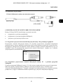
5. CONNECTORS AND ACCESORIES
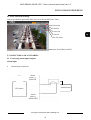
5.1. Connecting alarm inputs/outputs.
Alarm input
Alarm input connection
Switch/sensor
Alarm
input (-)
Alarm GND
Alarm
input (+)
Alarm IN
IP Camera

NVIP-5DN3615AV/IR-1P/F - User’s manual (short form) ver 1.0
All rights reserved © AAT Holding S.A.
18
5.2 Alarm output
Camera alarm output is an relay output type.
Alarm output electric connections (1A@30VDC /0.5A@125VAC)
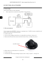
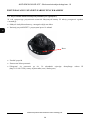
5.3 SD card installation
Camera supports microSD/SDHC cards up to a maximum size of 128GB. In order to install the card
properly, please follow the instructions below:
Turn the camera off
Unscrew screws holding camera dome cover using allen key and remove camera cover.
Mount micro SD card in the socket located at the camera’s base, according to the picture:
Mount camera cover dome and screw to camera base.
Turn the camera on
Check the micro SD card by checking its capacity in the “Config” “System”-> “Storage” tab.
CONNECTORS AND ACCESORIES
microSD card slot
Alarm
Output (-)
Alarm COM
(orange cord)
Alarm
Output (+)
Alarm NO
(brown cord)
Indicator
power
supply
Indicator
IP Camera

NVIP-5DN3615AV/IR-1P/F - User’s manual (short form) ver 1.0
All rights reserved © AAT Holding S.A.
19
5.4. Connecting audio input
Camera audio input allows to connect active microphone (with individual power supply).
6. RESTORING FACTORY DEFAULTS
NOVUS IP cameras allow to restore defaults via:
software (web browser level)
software (NMSiptool level)
hardware (reset button)
6.1. Restoring factory defaults by software means (web browser level)
User can restore default settings of the IP camera. To restore to default settings go to: “Config ->
Maintance -> Backup and Restore”. There is a possibility to keep some settings such as Network
Config, Security Configuration, Image Configuration.
6.2. Restoring factory defaults by software means (NMSiptool level)
NMSip (version 1.23.6 or later) allows to restore factory defaults. To restore settings find camera via
NMSiptool, click right mouse button and choose “ Restore default configuration”. Next, within 30
seconds, it is required to turn the camera power off and on.
CONNECTORS AND ACCESORIES
CAUTION! Power supply and microphone are not part of the set.
Strona się ładuje...
Strona się ładuje...
Strona się ładuje...
Strona się ładuje...
Strona się ładuje...
Strona się ładuje...
Strona się ładuje...
Strona się ładuje...
Strona się ładuje...
Strona się ładuje...
Strona się ładuje...
Strona się ładuje...
Strona się ładuje...
Strona się ładuje...
Strona się ładuje...
Strona się ładuje...
Strona się ładuje...
Strona się ładuje...
Strona się ładuje...
Strona się ładuje...
Strona się ładuje...
Strona się ładuje...
Strona się ładuje...
Strona się ładuje...
Strona się ładuje...
-
 1
1
-
 2
2
-
 3
3
-
 4
4
-
 5
5
-
 6
6
-
 7
7
-
 8
8
-
 9
9
-
 10
10
-
 11
11
-
 12
12
-
 13
13
-
 14
14
-
 15
15
-
 16
16
-
 17
17
-
 18
18
-
 19
19
-
 20
20
-
 21
21
-
 22
22
-
 23
23
-
 24
24
-
 25
25
-
 26
26
-
 27
27
-
 28
28
-
 29
29
-
 30
30
-
 31
31
-
 32
32
-
 33
33
-
 34
34
-
 35
35
-
 36
36
-
 37
37
-
 38
38
-
 39
39
-
 40
40
-
 41
41
-
 42
42
-
 43
43
-
 44
44
-
 45
45


Novus NVIP-5V-6402M/F (NVIP-5DN3615AV/IR-1P/F) Instrukcja obsługi
- Kategoria
- Kamery ochrony
- Typ
- Instrukcja obsługi
w innych językach
Powiązane artykuły
-
Novus NVIP-5VE-6402M/F Instrukcja obsługi
-
-
-
-
-
-
-
-
-