
Technical manual
Technisches handbuch
Livret technique
Technisch boek
Instrukcja techniczna
Manual tehnic
Technická dokumentácia
Technická dokumentace
EN
DE
FR
NL
PL
RO
SK
CS
MARK KLIMAT
06 61 000
06_61_000 Klimat:Opmaak 1 21-07-2009 16:12 Pagina 1

2
06_61_000 Klimat:Opmaak 1 21-07-2009 16:12 Pagina 2

EN
3
Read this document before
installing the appliance
Warning
Incorrect installation, adjustment, alteration, repair or maintenance activity may lead to material
damage or injury. All work must be carried out by approved, qualified professionals. If the appli-
ance is not positioned in accordance with the instructions, the warranty shall be rendered void.
If the manual refers to an image or table, a number will be shown between square brackets, for
example [3]. The number refers to images and tables at the back of the manual with the stated
number.
1.0 General
1.1 Application
The Mark Klimat air handling unit can be used for a variety of air handling purposes. It is able to
supply various types of buildings and rooms with ventilation air, either hot or cool as required.
The size of the Mark Klimat depends on the number of ventilation cycles required, and the heating
and/or cooling capacity. The Mark Klimat is available in various dimensions and air quantities from
5000m
3
/h to 69500m
3
/h. The air handling unit can be supplied in a number of assemblies on re-
quest. From a simple ventilation unit suitable for air intake and exhaust to a mixing box, filtering,
heating, cooling, humidifying, heat recovery and sound attenuation unit. If heating areas in which
there are corrosive vapours (chlorinated hydrocarbons in particular) which are either produced
directly in the area, or may be drawn in from the outside by the air handling unit via a connection
or an open connector, indirect gas heaters cannot be used because of the risk of corrosion. Con-
sult the manufacturer for use in, or close to, swimming pools.
The unit is suitable for the operating parameters indicated on the type plate.
– Median temperature (air, water, coolant and air humidity)
– The unit must not be used in explosive area unless otherwise indicated.
– The maximum current consumption must not be exceeded.
You may deviate from the agreements above only with the manufacturer’s agreement in writing.
Subject to change
The manufacturer is committed to constantly improving its products and reserves the right to
make changes in the specifications without prior notice. The technical details are considered cor-
rect but do not form the basis for a contract or warranty. All orders are accepted according to
the standard terms of our general sales and delivery conditions (available upon request).
06_61_000 Klimat:Opmaak 1 21-07-2009 16:12 Pagina 3

4
1.2 Type indication
Type dimensions (mm)
Klimat 15-15 975x975
Klimat 15-20 975x1280
Klimat 20-20 1280x1280
Klimat 25-20 1530x1280
Klimat 30-20 1890x1280
Klimat 35-25 2195x1530
Klimat 35-35 2195x1530
Klimat 40-35 2508x2195
1.3 General warnings
Incorrect installation, adjustment, alteration, maintenance activity or repair may lead to material
or environmental damage and/or injuries. The appliance should therefore be installed, adapted or
converted by a skilled and qualified installer, taking into account national and international regula-
tions. Faulty installation, adjustment, alteration, maintenance activity or repair shall render the
warranty void.
1.4 Safety
The air treatment unit must be fitted with a lockable isolator switch (not supplied as standard).
Always disconnect the appliance from the mains when carrying out maintenance or repairs. The
motor and fan take some time to stop after the voltage has been switched off. Wait for at least
two minutes before opening the fan doors. Always comply with national and/or regional regula-
tions.
2.0 Positioning the appliance
On receipt, check immediately that the supply had been delivered in full. Check also for any dam-
age caused during transportation. If what is delivered does not comply with the goods indicated
on the packing list, and/or damage during transportation is recorded, the recipient must state this
on the delivery note indicating the date of receipt. If the recipient fails to comply with the require-
ments above, he shall have no right to claim.
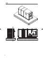
2.1 Assembly [15] [16] [17]
To avoid contact noise, we recommend that the air handling unit be placed on a level, vibration-
free floor or roof structure. The roof structure must be sufficiently stable, and must have enough
load-bearing points to prevent the air handling unit from bending. The air handling unit must be at-
tached to the roof structure. The unit must be placed on a level surface to ensure that any con-
densation is properly drained off. Air handling units incorrectly installed can cause the inspection
doors in the unit to jam and possibly result in the unit leaking. With units with a condensation ex-
tractor, the height of the installation structure must be at least the same, or higher, than the re-
quired siphon height. Note: if the air treatment unit replaces the roof in the location where it is
installed, the manufacturer must be aware of this in advance so that appropriate measures may be
applied.
06_61_000 Klimat:Opmaak 1 21-07-2009 16:12 Pagina 4

EN
5
Storage on-site
Parts of air handling units which are supplied in packaging must be unpacked immediately down to
the outer plating to prevent corrosion from forming, unless otherwise advised by the manufac-
turer. If the materials are not moved to the installation location immediately, the recipient must
apply the following measures:
– Remove the packaging.
– Store the appliance covered. (If for internal use)
– Store the appliance on a level surface.
– Seal any openings to prevent contaminants from getting into the appliance.
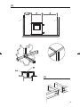
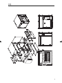
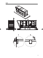
2.2 Transport to the installation location [1]
The air handling unit(s) are supplied complete or in parts. The recipient is responsible for unload-
ing and transport to the installation location. Note the following points:
– Use a fork lift truck with forks which are long enough to lift the appliance safely.
– Also be aware of the lifting torque, the weight of the appliance, the spread of weight and the
distance between the forks.
– Place appliances only in the position indicated.
2.3 Transport safety
If necessary, moving parts (which are sensitive to being transported) should be blocked. The fitter
should remove these blocks once the appliance is in its location. The blocks are red.
2.4 Lifting options [1]
The air handling unit is supplied in such a way that it can lifted. This may differ per appliance. Note
the instructions supplied with the appliance. If the appliance is supplied in several parts, these parts
must be lifted separately. In almost all cases, a hoist must be used during lifting to prevent damage
to the units. The angle of suspension must never be greater than 60º.
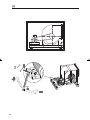
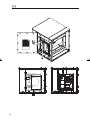
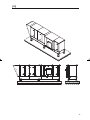
2.5 Minimum distances [2]
Always ensure that the largest components in air handling units can be exchanged. You can use
the following guidelines:
– the minimum width on the operating side is the width of the unit:
– motor at least 1 metre from the fan
– heat exchanger/cool exchanger, width of unit + 200 mm
– gas-fired heat source, width of unit + 400 mm
– bag filters (removable from the side) 700 mm
– keep to the width of the unit as a minimum for other parts which are removable from the side
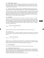
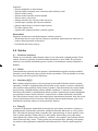
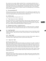
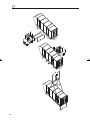
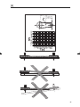
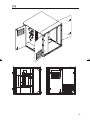
2.6 Installing the appliance [3]
The fitter must assemble appliances which are supplied in parts. The manufacturer provides the
necessary connectors within the scope of supply.
Assembling seam components:
– Apply the sealing tape provided to the sealing flange.
– Place the two parts of the unit as close together as possible.
– Pull the separate parts of the unit together via the assembly frame alone.
– Then seal the remaining seams with sealant.
Never use extruding parts of the appliance as a handle! See the sketch in the installation instruc-
tions [3] for the order of assembly. It is forbidden to step on the appliance as this may cause dam-
age. Inspection doors may need to be readjusted once the unit is assembled. The hinges provide
sufficient post-assembly adjustment. Attach the cover profiles to the component seam in accor-
dance with the drawing.
06_61_000 Klimat:Opmaak 1 21-07-2009 16:12 Pagina 5

6
2.7 Electrical connection
Electrical connections must be carried out in compliance with current general regional and local
regulations. Cables should not run, or be installed, in the vicinity of inspections doors, panel con-
nections and fastener profiles. To avoid damage, the electrical connection diagram in the branch-
ing box
must
be followed.
Earth connections already installed in the air handling unit must be removed. The air ducts from
the air handling unit to the appliance must be properly earthed.
2.8 Gas connection
The air handling units can be equipped with a gas-fired heat source The gas connection between
the gas-fired heat source and the gas network must be carried out in accordance with regional
and local regulations. For further details, please see the installation and operating instructions sup-
plied for the relevant gas-fired heat source. When installing the gas connection, make sure that in-
spection doors, panel connections and fastener profiles are not blocked. The pipes must never be
installed in the air flow of the Mark Klimat.
3.0 Start-up/shutdown
3.1 General
Appliances must be installed and started up by skilled personnel. It is important to be familiar be-
forehand with the installation, operating and maintenance instructions supplied as well as the
maintenance instructions for air handling units and any peripherals. Disregarding these instructions
could result in danger to the personnel carrying out the work, and damage the appliance. Do not
forget to instruct the user on the correct use and operation of the appliance and peripherals. The
appliance is suitable for the purpose for which it was designed and safe to operate only when fully
installed (building, water, air, electrics, condensation etc.).
3.2 Control activities
Check that all screw fittings have been sufficiently tightened.
Make sure that the air handling unit cannot be loaded in excess of the design parameters. Note in
particular;
– The fan’s maximum speed.
– The fan motor’s maximum current consumption.
– The maximum temperature inside the appliance < 60 ºC.
Checks prior to starting up the appliance for the first time.
– Has the appliance been cleaned internally?
– Have all tools been removed from the appliance?
– Has all the transport protection been removed?
– Can the shock absorbers under the fan frame move freely?
– Are the V-pulleys correctly aligned?
– Do the V-belts have the correct tension?
– Have any siphons been filled with water?
– Are the siphons protected from freezing?
– Have the heat exchanger(s)/gas feed pipes been bled?
– Have all the air ducts been installed?
– Are all the components in the duct system for the correct system pressure measurement?
– Are the motors connected according to the electrical diagram, and at the correct tension?
06_61_000 Klimat:Opmaak 1 21-07-2009 16:12 Pagina 6

EN
7
– Are the motor(s)/fan(s) rotating in the right direction?
– Are any servo motors rotating in the right direction?
– Have the end switches been adjusted to stand open at 90%?
– Have parts installed by third parties been tested to check that they are operational?
– Have all access doors been closed during testing of the installation?
– In the case of gas-fired units, never switch off the electrical voltage until the units have cooled
down completely.
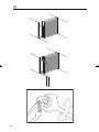
3.3 Starting up components
3.4 5.6 Fan [4][5]
Make sure that the appliance is disconnected from the mains when working on it. Remove any
(red) transport blocks. The axis of the fan(s) must always be horizontal. A load may be applied to
the shock absorbers only under pressure. Check the fan motor’s direction of rotation. Remove
the V-belt(s). Always check the direction of rotation when the motor is not under load. If the
motor is not rotating in the required direction, the electrical wiring in the motor(s)’ branching
box must be removed. Once the correct direction of rotation has been established, reinstall the
V-belt(s). Check whether the pulleys are in a single line. Check that the V-belt(s) have the correct
tension. The motor(s) is (are) on slide rails, which provide sufficient scope to (post-) tension the
V-belt(s).
Tension the slide rails as follows:
– Unscrew screw 1
– Use screw 2 to set the v-belt to the correct tension.
– Retighten locking screw 1.[4]
Once the unit has been fully operational for 0.5 and 4 hours, the V-belt(s) must be checked to en-
sure they are at the right tension. Once these tasks are complete, attach any protective grills (op-
tional). When the inspection doors are closed, the fan motor(s)’ current consumption can be
measured. Current consumptions can be measured correctly only if all the installation work has
been completed. The motor(s) and the fan(s) are selected on the basis of specifications provided
by the customer.
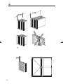
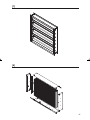
3.5 Filters [6]
– Check the filter safety setting and compare it with the values on the type plate.
– Check that the filters are correctly positioned (vertical).
– Check that the filters are sealed from damage.
3.6 Gravity shutter [7]
When installing the servo motors, make sure that no screws can hinder rotation of the fins in the
valve. The servo motors fitted are permitted a maximum torque of 20 Nm.
3.7 Flexible connection
To prevent vibrations to the (duct) system, the use of flexible connections is recommended. Make
sure that the flexible connections are able to move optimally. Where flexible connections could
come into contact with the external air, they must be properly thermally insulated to prevent
condensation.
In the Netherlands, flexible connections may not be used in a boiler room because of the risk of
fire. Any fire protection requirement may vary according to location. It is advisable to consult the
local regulations.
06_61_000 Klimat:Opmaak 1 21-07-2009 16:12 Pagina 7

8
3.8 Warm water, steam, cooler battery [9]
The batteries installed in the air handling unit are easy to dismantle. Connections and/or flanges
should be used. Make sure that the connection pipes do not restrict any other parts of the air
treatment unit. When tightening the connections or flanges, the battery pipe must be held back
with suitable equipment. No mechanical load may be placed on the connecting pipes. The battery
must be able to expand freely. Connect the battery in accordance with the flow direction indi-
cated. The fitter is responsible for bleeding and drawing off the pipes. The battery must be pro-
tected against the risk of freezing. Check this protection during the winter period.
3.9 Gas and oil-fired heat source: Föhn module [10]
The Föhn module is a gas or oil-fired air heater. The air heater is available from a capacity of
115kW to 415kW and in 5 sizes. The Föhn module can be used as a condensing or non-condens-
ing air heater as required. Check the Föhn’s maximum heating does not exceed 50K. See the type
plate on the heating element for details. Condensing air heaters must be connected by a siphon to
a sewage pipe. Make sure that there is an open connection between the siphon outlet and the
sewage pipe. Make sure the siphon is not in danger of freezing. Fill the siphon with water
before
starting up the appliance.
3.10 Gas-fired heat source: G+ module [11]
The G+ module is a gas-fired high-performance air heater. The air heater is available from a capac-
ity of 40kW to 150kW and in 5 sizes. The G+ module is a modulating, condensing air heater. The
integrated premix burner is able to modulate from 100% to 20%. To guarantee cooling of the
combustion boiler and the heat exchanger, the system fan is compressed. Check that the G+’s
maximum heating does not exceed 30K. See the type plate on the heating element for details.
Condensing air heaters must be connected by a siphon to a sewage pipe. Make sure that there is
an open connection between the siphon outlet and the sewage pipe. Make sure that the siphon is
not in danger of freezing. Fill the siphon with water
before
starting up the appliance.
3.11 Gas-fired heat source: GRE module [12]
The GRE module is a gas-fired air heater. The air heater is available from a capacity of 20kW to
95kW and in 7 sizes. The GRE module can be fitted with an on/off, high/low burner or a modulat-
ing/pulsating control. The GRE module is suitable where appliances of the same size are installed
in a series. This allows the maximum heating capacity to be increased to 2 x 95kW. Check that
the GRE’s maximum heating does not exceed 40K for a single appliance, and 60K maximum for
several appliances. See the type plate on the heating element for details.
3.12 Air bypass duct
The air bypass duct is used on gas-fired units such as the G+, GRE and the Föhn module with
greater air quantities. This keeps the air resistance across the units low, and restricts the motor
power required. If necessary, the air bypass duct can be fitted with a servo motor-controlled
valve.
3.13 Gas-fired heat source: Calflo make-up air system
The Calflo make-up air system is a heating system in which the combustion gases are fully mixed
with the air to be heated. CO
2
produced from the combustion of (natural) gas is diluted by adding
a large quantity of heating air. A maximum delta T of 55K is permitted for heating rooms. The
permitted concentration of CO
2
in the heated air blown out is maximum 2000 PPM. The Calflo
make-up air heater is suitable only for heating outdoor air. Air from the heated area must not be
recirculated under any circumstances.
06_61_000 Klimat:Opmaak 1 21-07-2009 16:12 Pagina 8

EN
9
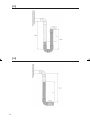
3.14 Siphon [13]
An air treatment unit usually contains components where condensation occurs. In such cases, ap-
propriate measures must be applied to remove the condensation responsibly.
A siphon must be connected to each condensation outlet or overflow connection. It is not per-
mitted to connect several outlet pipes to a single, shared siphon. The siphon water trap (H) must
be higher than the maximum under pressure and over pressure in mmWK for the appliance in re-
lation to atmospheric pressure (1mmWK= 10 Pa)
Appliance over pressure (Pa)
H(mm) = —————————————
10
The height between the condensation outlet and the overflow connection must also be of height
H (mm).
Siphon under pressure. [14]
This siphon is used where there is under pressure in the unit. The siphon should not be filled with
water following installation. The siphon will set its own level on start-up. If the siphon becomes
dry, the valve ensures that the siphon is closed off.
Appliance under pressure (Pa)
H(mm) = —————————————
10
The siphon pipe must not be connected directly to the sewage, but must be able to flow freely into
the sewage. Always ensure that parts carrying the (condensed) water cannot freeze. When starting
up the appliance after a long period out of operation, each siphon must first be filled with water.
3.15 Drip catcher [8]
If a drip catcher is fitted, it can be dismantled, and replaced after cleaning.
3.16 Shutting down
Appliances must be shut down by skilled personnel. It is important to be familiar with the installa-
tion, operating and maintenance instructions as well as the maintenance instructions for air han-
dling units and any peripherals in advance. Disregarding these instructions could result in danger
to the personnel carrying out the work, and damage to the appliance.
The air handling unit forms part of an air handling system.
For short periods of time.
– Terminate the demand for heat/cooling.
– Open the return air valve and close the outside air valve
– Shut off all valves
– Shut off the central heating pump
– Shut off water and hand valves
– Drain off any parts susceptible to freezing
– Blow dry the heat exchanger and connections fully with air
– Ventilate the unit fully until everything is dry.
– Remove the water from the siphons
– Switch off the mains switch and turn the unit off
06_61_000 Klimat:Opmaak 1 21-07-2009 16:12 Pagina 9

10
For longer periods of time.
Follow the points for shutting down the appliance for a short period.
– Check that any filters have not become dirty. If they are dirty, it is recommended that they be
removed and replaced to prevent mould from forming.
– De-tension the V-belts and the band(s).
4.0 Maintenance
4.1 General
The appliance must be subjected to maintenance at least once a year, more often if necessary. If
applicable, ask a qualified installer for maintenance advice. When carrying out maintenance, the ap-
pliance must have been shut down for an extended period. Make sure that you comply with all
safety rules.
4.2 Cleaning
The air treatment unit can be cleaned using commercially available cleaning agents. The cleaning
agent manufacturer’s instructions must, however, be followed. Cleaning agents must not contain
acids or other aggressive components.
4.3 Fan [4][5]
During maintenance (at least 1x per year), check the V-belt(s) for the correct tension and evi-
dence of wear and tear, and re-tension or replace if necessary. Always replace all the belts at the
same time on multi-belt drives. Always check that the pulleys are aligned. Clean the fan wheel if
necessary. Check the motor(s) and fan(s) for bearing noise, and replace bearings if necessary. It is
recommended that protection against the belt breaking be installed. The adjustment criteria for
new belts and pulleys are 80% of the nominal pressure. If the V-belt(s) are not sufficiently ten-
sioned or are broken, pressure over the fan(s) will drop or be lost. The pressure switch installed
will provide a signal, following which technical services need to apply appropriate measures.
4.4 Filters [6]
Depending on the operating conditions, check the filters at short intervals, and replace if neces-
sary. If the final pressure differential is exceeded, the filters should be changed. Consult the name
plate on the filter compartment for further information. Various filters may be used depending on
the unit’s use. Panel filters for low temperature, panel filters for high temperatures and/or bag fil-
ters. If the filters are located in the “cold” air flow, they may freeze over in the winter due to
“frost”. A filter monitoring pressure switch (optional) can provide an early indication if the filter is
dirty or blocked. If bag filters are used, make sure that the bags are inserted vertically. High tem-
perature filters (filter class 4) should be used as far as possible with a Calflo. These filters are lo-
cated after the heating section in order to prevent freezing. When replacing dirty filters, always
wear suitable personal protective equipment. Care must be taken when removing dirty filters and
fitting clean filters. Make sure filter frames are also correctly sealed. Dirty filters usually need to be
treated as special waste.
4.5 Gravity shutter [7]
The following maintenance activities should be carried out annually: Clean gravity shutters, never
lubricate bearings (plastic). Check that gravity shutters are current. Check that servo motors fit-
ted with end switches have the correct control functions.
06_61_000 Klimat:Opmaak 1 21-07-2009 16:12 Pagina 10

EN
11
4.6 Flexible connection
Check the flexible connection at least 1x per year.
4.7 Warm water, steam, cooler battery [9]
Care should be taken when cleaning Cu/Al batteries. If the battery is dirty in the air direction, it
can be blown clean in the opposite direction using compressed air or water. Ensure that the fins
do not deform during cleaning. You should also prevent dust from entering the air handling unit
and air duct.
4.8 Maintenance of gas-fired heat sources
See the installation and maintenance instructions supplied for the adjustment and maintenance of
gas-fired heat sources. Warning: never switch off the electrical voltage until the air heater has
cooled down completely.
4.9 Drip catcher [8]
Maintenance: Check the drip catcher for contamination, damage and corrosion. Clean the drip
catcher with compressed air, water steam or detergents containing soap. Check the water outlet
and siphon/S-trap.
4.10 Sound attenuator
If a sound attenuator is used, the wings cannot usually be removed from the attenuator section.
Never clean the soft attenuating material with water. It is preferable to use a vacuum cleaner
and/or a soft brush.
4.11 Heat recovery
Cross-flow heat exchanger
Under normal use of the air handling unit, the cross-flow heat exchanger would not be expected
to become contaminated. If the air handling unit is used in extreme conditions, such as in welding
areas, paint spraying locations, kitchens and the like, contamination may occur. Cleaning can be
completed as follows: dust and other particles can be easily removed using a brush. Take care if
using compressed air. Make sure that the element pack is not damaged. Greasy deposits can usu-
ally be removed with warm water. If necessary, suitable detergents may be used. It is recom-
mended that any gravity shutters and servo motors be cleaned annually.
Rotating heat exchanger
Check that the wheel is rotating in the correct direction. Rotate the heat exchanger periodically
during the summer months to utilize the exchanger’s self-cleaning capacity. A dirty surface may
have a negative impact on the exchanger’s performance.
06_61_000 Klimat:Opmaak 1 21-07-2009 16:12 Pagina 11

12
06_61_000 Klimat:Opmaak 1 21-07-2009 16:12 Pagina 12

13
Lesen Sie dieses Dokument sorgfältig
durch, bevor Sie das Gerät installieren
Warnhinweis
Fehlerhaft durchgeführte Installationen, Einstellungen, Änderungen, Reparaturen oder
Wartungsmaßnahmen können zu Sachschäden und Verletzungen führen. Alle Arbeiten
müssen von geprüften, qualifizierten Fachleuten durchgeführt werden. Falls das Gerät nicht
vorschriftsgemäß aufgestellt wird, erlischt die Garantie.
Wenn in der Anleitung auf eine Abbildung oder Tabelle verwiesen wird, wird eine Zahl in eckigen
Klammern angegeben, beispielsweise [3]. Die Zahl verweist auf die Abbildungen und Tabellen am
Ende der Anleitung mit der entsprechenden Nummer.
1.0 Allgemeines
1.1 Anwendungsbereich
Der Klimaschrank Mark Klimat wird für verschiedene Luftbehandlungszwecke eingesetzt. Verschie-
dene Typen von Gebäuden oder Räumen können hiermit mit erwärmter oder gekühlter Belüf-
tungsluft versorgt werden. Die Größe des Mark Klimat richtet sich nach der gewünschten
Luftaustauschzahl und der gewünschten Heiz- und/oder Kühlleistung. Das Mark Klimat-Gerät ist in
verschiedenen Größen und Luftleistungen von 5.000 m³/h bis 69.500 m³/h erhältlich. Der Klima-
schrank kann auf Wunsch in vielen verschiedenen Varianten geliefert werden: Vom einfachen Lüf-
tungsschrank für das Einblasen oder Absaugen von Luft bis hin zum Mischluftschrank oder mit
Filterung, Heizung, Kühlung, Befeuchtung, Wärmerückgewinnung und schalldämmenden Vorrich-
tungen. Zum Heizen von Räumen, in denen korrosive Dämpfe vorhanden sind (insbesondere chlo-
rierte Kohlenwasserstoffe), die entweder direkt aus dem Raum oder von außen über einen
Anschluss oder eine offene Verbindung vom Klimaschrank angesaugt werden können, können indi-
rekt (gas)beheizte Wärmequellen wegen der Korrosionsgefahr am Wärmetauscher nicht eingesetzt
werden. Für die Anwendung in oder bei Schwimmbädern wenden Sie sich bitte an den Hersteller.
Das Gerät ist für die auf dem Typenschild angegebenen Betriebsparameter ausgelegt:
– Mediumtemperatur (Luft, Wasser, Kältemittel und Luftfeuchtigkeit)
– Das Gerät darf, sofern nichts anders angegeben ist, nicht in explosionsgeschützten Bereichen
betrieben werden.
– Die maximale Stromaufnahme darf nicht überschritten werden.
Von den oben genannten Bestimmungen darf nur mit schriftlicher Genehmigung des Herstellers
abgewichen werden.
Änderungen vorbehalten
Der Hersteller strebt eine kontinuierliche Verbesserung der Produkte an und behält sich das
Recht vor, ohne vorherige Mitteilung Änderungen an den technischen Daten vorzunehmen. Die
technischen Angaben werden als korrekt angenommen, bilden aber keine Grundlage für einen
Vertrag oder Gewährleistungsansprüche. Alle Bestellungen werden gemäß den Standardkonditio-
nen in unseren allgemeinen Verkaufs- und Lieferbedingungen angenommen (lieferbar auf Anfrage).
DE
06_61_000 Klimat:Opmaak 1 21-07-2009 16:12 Pagina 13

14
1.2 Typkennzeichnung
Typ Maß (mm)
Klimat 15-15 975x975
Klimat 15-20 975x1280
Klimat 20-20 1280x1280
Klimat 25-20 1530x1280
Klimat 30-20 1890x1280
Klimat 35-25 2195x1530
Klimat 35-35 2195x2195
Klimat 40-35 2508x2195
1.3 Allgemeine Warnhinweise:
Fehlerhafte Installation, Einstellung, Änderungen, Wartungsmaßnahmen oder Reparaturen können
zu Sach- und Umweltschäden oder Verletzungen führen. Daher darf das Gerät nur von einem
sachkundigen und qualifizierten Installateur unter Beachtung der nationalen und internationalen
Vorschriften installiert, geändert oder umgebaut werden. Bei fehlerhafter Installation, Einstellung,
Änderung und fehlerhaften Wartungsmaßnahmen oder Instandsetzungen erlischt die Gewährlei-
stung.
1.4 Sicherheit
Der Klimaschrank muss mit einem abschließbaren Trennschalter (keine Standardlieferung) verse-
hen sein. Bei Wartung und Reparaturen muss das Gerät stets spannungsfrei gemacht werden.
Motor und Lüfter haben eine Auslaufzeit nach dem Abschalten des Stroms. Warten Sie minde-
stens zwei Minuten, bevor Sie die Tür des Lüfterteils öffnen. Weiterhin müssen die überregionalen
und/oder lokalen Vorschriften beachtet werden.
2.0 Aufstellung des Geräts
Beim Eingang der Güter die Lieferung sofort anhand des Lieferscheins auf Vollständigkeit überprü-
fen. Außerdem auf eventuelle Transportschäden überprüfen. Wenn die Lieferung nicht mit den auf
dem Lieferschein genannten Gütern und/oder festgestellten Transportschäden übereinstimmt,
muss das auf dem vom Empfänger unterschriebenen Frachtbrief unter Angabe des Eingangsdatums
gemeldet werden. Bei Nichteinhaltung des Vorgesagten entfallen jegliche Gewährleistungsansprü-
che des Empfängers.
2.1 Aufstellung [15] [16] [17]
Zur Vermeidung von Kontaktschall wird empfohlen, den Klimaschrank auf einer ebenen, schwin-
gungsfreien Boden- oder Dachkonstruktion aufzustellen. Die Dachkonstruktion muss ausreichend
stabil ausgeführt sein und muss über entsprechende Auflagerpunkte verfügen, um ein Durchbiegen
des Klimaschranks zu verhindern. Der Klimaschrank muss an der Dachkonstruktion befestigt wer-
den. Das Gerät muss waagrecht installiert werden, um einen einwandfreien Ablauf von eventuell
auftretendem Kondenswasser zu gewährleisten. Eine unsachgemäße Aufstellung von Klimaschrän-
ken kann dazu führen, dass die Kontrolltüren in den Schränken klemmen bzw. dass die Schränke
undicht werden. Bei Geräten mit Kondensablauf muss die Höhe der Aufstellungskonstruktion min-
destens gleich oder höher als die benötigte Siphonhöhe sein. Achtung: Wenn der Luftbehandlungs-
schrank am Aufstellungsort das Dach ersetzt, muss dies dem Hersteller vorher mitgeteilt werden,
damit geeignete Maßnahmen getroffen werden können.
06_61_000 Klimat:Opmaak 1 21-07-2009 16:12 Pagina 14

15
Lagerung auf der Baustelle
Teile der Klimaschränke, die in Verpackungsfolie geliefert werden, müssen wegen Korrosionsbil-
dung an der Außenabdeckung sofort ausgepackt werden, sofern nicht vom Hersteller etwas ande-
res angegeben ist. Wenn die Materialien nicht sofort zum Aufstellungsort gebracht werden, muss
der Empfänger folgende Maßnahmen treffen:
– Verpackungsfolie entfernen.
– Gerät abgedeckt lagern. (bei Innenmontage)
– Gerät auf einer ebenen Fläche lagern.
– Eventuelle Öffnungen verschließen, um eine Verschmutzung im Gerät zu vermeiden.
2.2 Transport zur Baustelle [1]
Der Klimaschrank/die Klimaschränke wird/werden komplett oder in Teilen geliefert. Der Empfän-
ger ist für das Abladen und den internen Transport zum Aufstellungsort verantwortlich. Hierbei
ist auf die folgenden Punkte zu achten:
– Verwenden Sie einen Gabelstapler mit entsprechend langen Gabeln, um das Gerät sicher heben
zu können.
– Beachten Sie außerdem das Hubmoment, das Gewicht des Geräts, die Gewichtsverteilung und
den Abstand zwischen den Gabeln.
– Geräte ausschließlich in der angegeben Position bewegen.
2.3 Transportsicherungen
Soweit erforderlich, werden die beweglichen (transportempfindlichen) Teile gesichert. Der Instal-
lateur muss, nachdem das Gerät aufgestellt ist, diese Transportsicherungen entfernen. Die Siche-
rungen sind an der roten Farbe zu erkennen.
2.4 Hebepunkte [1]
Der Klimaschrank ist mit Hebepunkten versehen. Diese können pro Gerät unterschiedlich sein.
Bitte beachten Sie die dem Gerät beigefügte Anleitung. Wenn ein Gerät in mehreren Teilen gelie-
fert wird, müssen diese Teile getrennt gehoben werden. Praktisch immer muss, um eine Beschädi-
gung der Schränke zu vermeiden, zum Heben eine Traverse eingesetzt werden. Der
Aufhängewinkel darf höchstens 60° betragen.
2.5 Mindestabstände [2]
Achten Sie darauf, dass die größten Bauteile im Klimaschrank ausgetauscht werden können. Hier-
bei können die folgenden Richtlinien eingehalten werden:
– Mindestbreite auf der Bedienseite ist die Schrankbreite:
– Lüftermotor ist minimal 1 m
– Wärmetauscher/Kältetauscher: Gerätebreite + 200 mm
– Gasgefeuerte Wärmequelle: Gerätebreite + 400 mm
– Taschenfilter (zur Seite ausziehbar): 700 mm
– Bei den übrigen zur Seite ausziehbaren Teilen mindestens die Schrankbreite einhalten
2.6 Aufstellung des Geräts [3]
Geräte, die in Teilen geliefert werden, müssen vom Installateur zusammengebaut werden. Die be-
nötigten Verbindungsmittel werden vom Hersteller mit der Sendung mitgeliefert.
Zusammenbau Teilnaht:
– Den mitgelieferten Dichtungsstreifen auf dem Dichtungsflansch anbringen.
– Beide Schrankteile so nahe wie möglich aneinander stellen.
– Die einzelnen Schrankteile ausschließlich über den Aufstellungsrahmen aufeinander zu bewegen.
– Danach die verbleibenden Nähte mit Kitt abdichten.
DE
06_61_000 Klimat:Opmaak 1 21-07-2009 16:12 Pagina 15

16
Vorstehende Teile des Geräts niemals als Griff verwenden! Bezüglich der Reihenfolge des Zusam-
menbaus siehe die Abbildungen in der Einbauvorschrift [3]. Wegen möglicher Schäden ist es ver-
boten, das Gerät zu begehen. Inspektionstüren müssen nach dem Zusammenbau der Schränke ggf.
erneut eingestellt werden. An den Scharnieren bestehen ausreichend Möglichkeiten zum Nachstel-
len. Abdeckprofile an der Teilnaht gemäß Zeichnung über dem Dach anbringen.
2.7 Elektrischer Anschluss
Elektrische Anschlüsse müssen gemäß den allgemein geltenden überregionalen und lokalen Vor-
schriften ausgeführt werden. Kabeldurchführungen und -befestigungen in der Nähe von Inspekti-
onstüren, Strahlerverbindungen und Klemmprofilen müssen vermieden werden. Zur Vermeidung
von Schäden muss das elektrische Anschlussschema im Schaltschrank beachtet werden.
Vormontierte Erdungsleitungen im Klimaschrank dürfen nicht entfernt werden. Die am Klima-
schrank montierten Luftkanäle zum Gerät müssen ordnungsgemäß geerdet werden.
2.8 Gasanschluss
Klimaschränke können mit einer gasgefeuerten Wärmequelle versehen werden. Der Gasanschluss
zwischen der gasgefeuerten Wärmequelle und dem Gasnetz muss gemäß den landesweiten und lo-
kalen Vorschriften ausgeführt werden. Für weitere Details wird auf die mitgelieferte Installations–
und Bedienungsanleitung der entsprechenden gasgefeuerten Wärmequelle verwiesen. Bei der
Montage des Gasanschlusses muss vermieden werden, dass Inspektionstüren, Strahlerverbindun-
gen und Klemmprofile blockiert werden. Die Gasleitung darf nicht im Luftstrom des Mark Klimat
verlegt werden.
3.0 Inbetriebnahme/Außerbetriebnahme
3.1 Allgemeines
Installation und Inbetriebnahme müssen von Fachpersonal durchgeführt werden. Zuvor müssen Sie
sich mit den mitgelieferten Installations-, Bedienungs- und Wartungsvorschriften für die Klima-
schränke und eventuelle Peripherie vertraut machen. Nichtbeachtung dieser Vorschriften kann das
Personal gefährden, das die Arbeiten durchführt, und Schäden am Gerät verursachen. Bitte denken
Sie daran, den Benutzer in die ordnungsgemäße Benutzung und Bedienung des Geräts und der Pe-
ripherie einzuweisen. Erst nachdem das Gerät vollständig installiert wurde (gebäudetechnisch,
Wasser, Luft, elektrisch, Kondensat usw.) kann es seine Aufgabe erfüllen und ist eine sichere Funk-
tion gewährleistet.
3.2 Überprüfungsarbeiten
Prüfen Sie, ob alle Schraubverbindungen ausreichend festgezogen sind.
Beachten Sie ebenso, dass der Klimaschrank nicht außerhalb der Konstruktionsparameter belastet
werden darf. Hierbei ist insbesondere zu beachten:
– Die maximale Drehzahl des Lüfters.
– Die maximale Stromaufnahme des Lüftermotors/der Lüftermotoren.
– Maximale Temperatur im Gerät < 60 ºC.
Überprüfung vor der ersten Inbetriebnahme.
– Wurde das Gerät innen gereinigt?
– Wurde kein Werkzeug im Gerät zurückgelassen?
– Wurden die Transportsicherungen entfernt?
– Können sich die Schwingungsdämpfer unter dem Lüfterrahmen frei bewegen?
– Wurden die Riemenscheiben korrekt ausgerichtet?
06_61_000 Klimat:Opmaak 1 21-07-2009 16:12 Pagina 16

17
– Haben die Keilriemen die richtige Spannung?
– Wurden eventuell vorhandene Siphons mit Wasser gefüllt?
– Sind die Siphons frostgeschützt?
– Wurden die Wärmetauscher/Gaszuleitungen entlüftet?
– Wurden alle Luftkanäle montiert?
– Wurden alle Elemente für die richtige Systemdruckmessung im Kanalsystem eingesetzt?
– Wurden die Motoren anhand des Schaltplans und mit der richtigen Spannung angeschlossen?
– Stimmt der Drehsinn des Motors (der Motoren)/Lüfter(s) ?
– Stimmt der Drehsinn der (eventuellen) Servomotoren?
– Wurden die Endschalter auf 90% offen eingestellt?
– Wurden Bauteile Dritter installiert und auf einwandfreie Funktion geprüft?
– Wurden alle Zugangstüren während der Installationsprüfung geschlossen?
– Bei gasgefeuerten Geräten nie die Stromversorgung abschalten, bevor nicht die Geräte vollstän-
dig abgekühlt sind.
3.3 Inbetriebnahme der Bauteile
3.4 Lüfter [4][5]
Achten Sie darauf, dass das Gerät während der Arbeiten spannungsfrei gemacht wird. Eventuell
angebrachte (rote) Transportsicherungen entfernen. Die Lüfterwellen müssen immer horizontal
liegen. Die verwendeten Schwingungsdämpfer dürften nur auf Druck belastet werden. Den Dreh-
sinn des Lüftermotors/der Lüftermotoren prüfen. Den (die) Keilriemen entfernen. Den Drehsinn
immer bei unbelastetem Motor überprüfen. Wenn der Motor nicht den gewünschten Drehsinn
hat, muss die elektrische Verkabelung im Schaltschrank des Motors/der Motoren geändert wer-
den. Nachdem der richtige Drehsinn festgestellt wurde, den (die) Keilriemen wieder montieren.
Prüfen, ob die Riemenscheiben fluchten. Prüfen, ob der/die Keilriemen die richtige Spannung
hat/haben. Der/die Motor(en) ist/sind auf Spannschienen montiert, was ein (Nach-)Spannen
des/der Keilriemen ermöglicht.
Zum Spannen gehen Sie wie folgt vor:
– Sicherungsschraube 1 lösen
– Mit Schraube 2 den Keilriemen korrekt spannen.
– Sicherungsschraube 1 wieder festziehen.[4]
Wenn das Gerät 0,5 bis 4 Stunden unter Volllast gelaufen ist, muss/müssen der/die Keilriemen auf
richtige Spannung geprüft werden. Nach Durchführung der oben genannten Schritte eventuelle
Schutzgitter (optional) montieren. Die Stromaufnahme des/der Lüftermotor(en) kann bei ge-
schlossenen Inspektionstüren gemessen werden. Eine korrekte Messung der Stromaufnahme ist
erst möglich, nachdem die Installationsarbeiten vollständig abgeschlossen sind. Der/die Motor(en)
und der/die Lüfter wurden nach den vom Kunden vorgegebenen Anforderungen ausgewählt.
3.5 Filter [6]
– Einstellung des Filterschutzes prüfen und diese mit den Werten auf dem Typenschild verglei-
chen.
– Prüfen, ob die Filter korrekt angebracht sind (vertikal).
– Filter auf Dichtigkeit und Beschädigung prüfen.
3.6 Jalousieklappe [7]
Achten Sie darauf, dass bei der Montage der Servomotoren keine Schrauben das Drehen der La-
mellen behindern. Die verwendeten Servomotoren dürfen maximal ein Drehmoment von 20 Nm
haben.
DE
06_61_000 Klimat:Opmaak 1 21-07-2009 16:12 Pagina 17

18
3.7 Flexible Verbindung
Um die Übertragung von Schwingungen in das Kanalsystem zu vermeiden, empfiehlt es sich, flexi-
ble Verbindungen zu verwenden. Achten Sie darauf, dass sich die flexiblen Verbindungen optimal
bewegen können. Wenn flexible Verbindungen mit der Außenluft in Berührung kommen können,
müssen diese in geeigneter Weise thermisch isoliert werden, um Kondensation zu verhindern.
Für die Niederlande gilt, dass die Anwendung flexibler Verbindungen in einem Heizungsraum
wegen Brandgefahr nicht erlaubt ist. Die Brandschutzbestimmungen können lokal unterschiedlich
sein. Es empfiehlt sich, die lokalen Vorschriften nachzulesen.
3.8 Warmwasser-, Dampf-, Kühlbatterien [9]
Die im Klimaschrank montierten Batterien können in einfacher Weise ausgebaut werden. Hierzu
müssen Kupplungen und/oder Flansche verwendet werden. Achten Sie darauf, dass die Anschluss-
leitungen keine anderen Teile des Klimaschrank stören. Beim Festziehen der Kupplungen oder
Flansche muss das Rohr der Batterie mit dem entsprechendem Werkzeug gegengehalten werden.
Die Anschlussrohre dürfen nicht mechanisch belastet werden. Die Batterie muss sich frei ausdeh-
nen können. Die Batterie in der angegebenen Strömungsrichtung anschließen. Der Installateur ist
zuständig für die Entlüftung und den Ablass. Die Batterie muss vor Frost geschützt werden. Diesen
Schutz während der Wintersaison überprüfen.
3.9 Gas- oder ölgefeuerte Wärmequelle: Fönmodul[10]
Das Fönmodul ist ein gas- oder ölgefeuerter Lufterhitzer. Der Lufterhitzer ist mit einer Leistung
von 115 kW bis 415 kW sowie in 5 Größen lieferbar. Das Fönmodul kann wahlweise als konden-
sierender oder nichtkondensierender Lufterhitzer ausgeführt werden. Prüfen Sie, ob die maximale
Erwärmung des Föns 50 K nicht überschreitet. Bezüglich der Daten siehe das Typenschild im Er-
wärmungsbereich. Kondensierende Lufterhitzer müssen mittels eines Siphons an die Kanalisation
angeschlossen werden. Es muss dafür gesorgt werden, dass eine offene Verbindung zwischen dem
Auslass des Siphons und der Kanalisation besteht. Siphon vor Frost schützen. Vor Inbetriebnahme
des Geräts Siphon mit Wasser füllen.
3.10 Gasgefeuerte Wärmequelle: G+ Modul [11]
Das G+ Modul ist ein hocheffizienter gasgefeuerter Lufterhitzer. Der Lufterhitzer ist mit einer Lei-
stung zwischen 40 kW und 150 kW sowie in 5 Abmessungen lieferbar. Das G+ Modul ist ein
hocheffizienter modulierender Lufterhitzer. Der eingebaute Premix-Brenner moduliert von 100%
bis 20%. Um die Kühlung des Heizkessels und des Wärmetauschers sicherzustellen, ist der Sy-
stemlüfter blasend installiert. Prüfen Sie, ob die maximale Erwärmung des G+ 30 K nicht über-
schreitet. Bezüglich der Daten siehe das Typenschild im Erwärmungsbereich. Kondensierende
Lufterhitzer müssen mittels eines Siphons an die Kanalisation angeschlossen werden. Es muss dafür
gesorgt werden, dass eine offene Verbindung zwischen dem Auslass des Siphons und der Kanalisa-
tion besteht. Siphon vor Frost schützen. Vor Inbetriebnahme des Geräts den Siphon mit Wasser
füllen.
3.11 Gasgefeuerte Wärmequelle: GRE-Modul [12]
Das GRE-Modul ist ein gasgefeuerter Lufterhitzer. Der Lufterhitzer ist mit einer Leistung von 20
kW bis 95 kW sowie in 7 Größen lieferbar. Das GRE-Modul kann mit einer Brenner Ein/Aus-,
hoch/niedrig- oder mit einer modulierenden/pulsierenden Regelung ausgeführt sein. Das GRE-
Modul ist für die Serienanordnung von Geräten mit gleichen Abmessungen geeignet. Hierdurch
lässt sich die maximale Heizleistung auf 2 x 95 kW erhöhen. Prüfen Sie, ob die maximale Erwär-
mung des GRE für ein Gerät 40 K und für mehrere Geräte 60 K nicht überschreitet. Bezüglich der
Daten siehe das Typenschild im Erwärmungsbereich.
06_61_000 Klimat:Opmaak 1 21-07-2009 16:12 Pagina 18

19
3.12 Bypass-Luftkanal
Der Bypass-Luftkanal wird bei gasgefeuerten Geräten wie G+, GRE- und dem Fönmodul bei grö-
ßeren Luftmengen eingesetzt Hierdurch wird der Luftwiderstand der Geräte verringert und die
erforderliche Motorleistung begrenzt. Falls erforderlich, wird der Bypass-Luftkanal mit einer ser-
vomotorgesteuerten Klappe versehen.
3.13 Gasgefeuerte Wärmequelle: Calflo-Mischluftsystem
Das Calflo-Mischluftsystem ist ein Heizsystem, bei dem die Verbrennungsgase vollständig mit der
zu erwärmenden Luft gemischt werden. Das bei der Verbrennung von (Erd-)Gas entstehende CO
2
wird durch Hinzufügung einer großen Heizluftmenge verdünnt. Für die Beheizung von Räumen ist
eine maximale Delta T von 55 K zulässig. Die zulässige CO
2
-Konzentration in ausgeblasener er-
wärmter Luft beträgt maximal 2000 ppm. Der Calflo-Mischlufterwärmer eignet sich ausschließlich
für das Erwärmen von Außenluft. Umwälzung von Luft aus dem beheizten Raum ist unter keinen
Umständen erlaubt.
3.14 Siphon [13]
Ein Klimaschrank enthält oft Bauteile, durch die Kondensat gebildet wird. In diesen Fällen müssen
Maßnahmen ergriffen werden, um das vorhandene Kondensat in geeigneter Weise ablaufen zu lassen.
An jeden Kondensatablauf- oder Überlaufanschluss muss ein Siphon angeschlossen werden. Mehrere
Ablaufleitungen dürfen nicht an einen einzigen gemeinsamen Siphon angeschlossen werden. Der
Wasserverschlussdruck (H) des Siphons muss höher sein als der maximale Unter- bzw. Überdruck
in mm WS des betreffenden Geräts gegenüber dem atmosphärischen Druck (1 mm WS = 10 Pa).
Überdruck des Geräts (Pa)
H(mm) = —————————————
10
Der Höhenunterschied zwischen Kondensatabfuhr und dem Überlaufanschluss muss ebenfalls das
Maß H (mm) haben.
Unterdrucksiphon. [14]
Ein solcher Siphon wird eingesetzt, wenn im Schrank ein Unterdruck vorhanden ist. Nach der
Montage muss der Siphon nicht mit Wasser gefüllt werden. Bei Ingebrauchnahme stellt sich der
Füllstand des Siphons von selbst ein. Falls der Siphon austrocknet, sorgt die Klappe für den Ver-
schluss des Siphons.
Geräteunterdruck (Pa)
H(mm) = —————————————
10
Die Siphonleitung darf nicht direkt an das Abwassersystem angeschlossen werden, sondern muss
einen freien Ablauf in dieses haben. Stellen Sie sicher, dass (kondens-)wasserführende Teile nicht
einfrieren können. Bei der Inbetriebnahme und nach längerer Nichtbenutzung muss jeder Siphon
zuerst mit Wasser gefüllt werden.
3.15 Tropfenfänger [8]
Wenn ein Tropfenfänger angebracht wurde, kann er abgebaut und nach der Reinigung wieder an-
gebracht werden.
DE
06_61_000 Klimat:Opmaak 1 21-07-2009 16:12 Pagina 19

20
3.16 Stilllegung
Dies muss von Fachpersonal durchgeführt werden. Zuvor müssen Sie sich mit den Installations-,
Bedienungs- und Wartungsvorschriften für Luftbehandlungsschränke und eventuelle Peripherie
vertraut machen. Nichtbeachtung dieser Vorschriften kann das Personal gefährden, das die Arbei-
ten durchführt, und Schäden am Gerät verursachen.
Der Klimaschrank ist Teil eines Klimatisierungssystems.
Für kurze Zeit
– Den Wärme-/Kältebedarf beenden.
– Rückluftklappe öffnen und Frischluftklappe schließen
– Alle Ventile schließen
– Zentralheizungspumpe absperren
– Wasser- und Handabsperrventile zudrehen
– Kälteempfindliche Teile entleeren
– Wärmetauscher und Anschlüsse sorgfältig mit Luft trockenblasen
– Das Gerät vollständig nachbelüften, bis alles trocken ist.
– Das Wasser aus den Siphons entfernen
– Hauptschalter ausschalten und das Gerät abschließen
Für längere Zeit
Beachten Sie die Anweisungen für eine kurzzeitige Außerbetriebnahme.
– Verschmutzung eventuell vorhandener Filter prüfen. Wenn diese verschmutzt sind, empfiehlt es
sich, sie wegen der Gefahr von Schimmelbildung zu entfernen bzw. zu ersetzen.
– Die Keilriemen entspannen und den/die Riemen entfernen.
4.0 Wartung
4.1 Allgemein
Die Wartung für das Gerät hat mindestens ein Mal pro Jahr zu erfolgen, im Bedarfsfall häufiger.
Wenden Sie sich bei Fragen zur Wartung an einen qualifizierten Installateur. Bei der Durchführung
der Wartungsarbeiten ist das Gerät für längere Zeit außer Betrieb zu nehmen. Achten Sie auf die
Einhaltung aller Sicherheitsvorschriften.
4.2 Reinigung
Der Klimaschrank kann mit den handelsüblichen Mitteln gereinigt werden. Dabei müssen die Her-
stellervorschriften beachtet werden. Diese Mittel dürfen keine sauren oder sonstigen aggressiven
Inhaltsstoffe enthalten.
4.3 Lüfter [4][5]
Bei der Wartung Keilriemen (mindestens einmal jährlich) auf Spannung und Verschleiß prüfen und
ggf. nachspannen oder ersetzen. Bei einem Antrieb mit mehreren Riemen müssen immer alle Rie-
men gleichzeitig ersetzt werden. Prüfen, ob die Riemen fluchten. Falls erforderlich, das Lüfterrad
reinigen. Motor(en) und Lüfter auf Lagergeräusche prüfen, ggf. die Lager ersetzen. Es wird empfoh-
len, eine Schutzvorrichtung für Keilriemenbruch zu montieren. Bei neuen Riemen und Riemen-
scheiben sind die Einstellkriterien 80% des Nenndrucks. Wenn die Keilriemen ungenügende
Spannung haben oder gebrochen sind, sinkt der vom Lüfter erzeugte Druck bzw. fällt weg. Der
montierte Druckschalter sendet ein Signal aus, woraufhin der technische Dienst entsprechende
Maßnahmen ergreifen muss.
06_61_000 Klimat:Opmaak 1 21-07-2009 16:12 Pagina 20
Strona się ładuje...
Strona się ładuje...
Strona się ładuje...
Strona się ładuje...
Strona się ładuje...
Strona się ładuje...
Strona się ładuje...
Strona się ładuje...
Strona się ładuje...
Strona się ładuje...
Strona się ładuje...
Strona się ładuje...
Strona się ładuje...
Strona się ładuje...
Strona się ładuje...
Strona się ładuje...
Strona się ładuje...
Strona się ładuje...
Strona się ładuje...
Strona się ładuje...
Strona się ładuje...
Strona się ładuje...
Strona się ładuje...
Strona się ładuje...
Strona się ładuje...
Strona się ładuje...
Strona się ładuje...
Strona się ładuje...
Strona się ładuje...
Strona się ładuje...
Strona się ładuje...
Strona się ładuje...
Strona się ładuje...
Strona się ładuje...
Strona się ładuje...
Strona się ładuje...
Strona się ładuje...
Strona się ładuje...
Strona się ładuje...
Strona się ładuje...
Strona się ładuje...
Strona się ładuje...
Strona się ładuje...
Strona się ładuje...
Strona się ładuje...
Strona się ładuje...
Strona się ładuje...
Strona się ładuje...
Strona się ładuje...
Strona się ładuje...
Strona się ładuje...
Strona się ładuje...
Strona się ładuje...
Strona się ładuje...
Strona się ładuje...
Strona się ładuje...
Strona się ładuje...
Strona się ładuje...
Strona się ładuje...
Strona się ładuje...
Strona się ładuje...
Strona się ładuje...
Strona się ładuje...
Strona się ładuje...
Strona się ładuje...
Strona się ładuje...
Strona się ładuje...
Strona się ładuje...
Strona się ładuje...
Strona się ładuje...
Strona się ładuje...
Strona się ładuje...
Strona się ładuje...
Strona się ładuje...
Strona się ładuje...
Strona się ładuje...
-
 1
1
-
 2
2
-
 3
3
-
 4
4
-
 5
5
-
 6
6
-
 7
7
-
 8
8
-
 9
9
-
 10
10
-
 11
11
-
 12
12
-
 13
13
-
 14
14
-
 15
15
-
 16
16
-
 17
17
-
 18
18
-
 19
19
-
 20
20
-
 21
21
-
 22
22
-
 23
23
-
 24
24
-
 25
25
-
 26
26
-
 27
27
-
 28
28
-
 29
29
-
 30
30
-
 31
31
-
 32
32
-
 33
33
-
 34
34
-
 35
35
-
 36
36
-
 37
37
-
 38
38
-
 39
39
-
 40
40
-
 41
41
-
 42
42
-
 43
43
-
 44
44
-
 45
45
-
 46
46
-
 47
47
-
 48
48
-
 49
49
-
 50
50
-
 51
51
-
 52
52
-
 53
53
-
 54
54
-
 55
55
-
 56
56
-
 57
57
-
 58
58
-
 59
59
-
 60
60
-
 61
61
-
 62
62
-
 63
63
-
 64
64
-
 65
65
-
 66
66
-
 67
67
-
 68
68
-
 69
69
-
 70
70
-
 71
71
-
 72
72
-
 73
73
-
 74
74
-
 75
75
-
 76
76
-
 77
77
-
 78
78
-
 79
79
-
 80
80
-
 81
81
-
 82
82
-
 83
83
-
 84
84
-
 85
85
-
 86
86
-
 87
87
-
 88
88
-
 89
89
-
 90
90
-
 91
91
-
 92
92
-
 93
93
-
 94
94
-
 95
95
-
 96
96


Mark Klimat 15-15 Technical Manual
- Typ
- Technical Manual
- Niniejsza instrukcja jest również odpowiednia dla
w innych językach
- čeština: Mark Klimat 15-15
- Deutsch: Mark Klimat 15-15
- slovenčina: Mark Klimat 15-15
- français: Mark Klimat 15-15
- English: Mark Klimat 15-15
- Nederlands: Mark Klimat 15-15
- română: Mark Klimat 15-15
Powiązane artykuły
Inne dokumenty
-
Steba 39.02.00 Karta katalogowa
-
Dometic RM 7400(L) Instrukcja obsługi
-
Danfoss Air Units Instrukcja instalacji
-
-
-
Whirlpool MFW 6512 KKW instrukcja
-
-
Brandt WFS0835A Instrukcja obsługi
-
Kampmann Katherm QK Instrukcja instalacji
-
Philips HP4841/00 Product Datasheet