Strona się ładuje...

Ventilation Products
AirCycler® FRV
Installation & User’s Guide
VENTILATION MADE BREEZY!™
a breeze to install • a breeze to use

2
www.aircycler.com
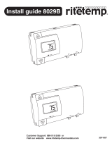
4.50 in.
11.5 cm
3.50 in.
9 cm
1.30 in.
3.4 cm
INTRODUCTION
The AirCycler® is a digital programmable furnace fan timer. By oper-
ating the furnace fan periodically, the AirCycler® improves indoor air
quality and thermal comfort by circulating and ltering indoor air. The
AirCycler ® enables the furnace fan to operate more consistently and
eciently with programmable ON and OFF times.
BENEFITS
• Mixes and circulates indoor air
• Eliminates stagnant air
• Creates even temperature and humidity levels
• Filters indoor air consistently provides an economical alternative
to continuously running the furnace fan
APPLICATIONS
Digital Programmable Furnace Fan timer
The AirCycler® automatically turns on the furnace fan for a set period of time only when it detects the system has been
inactive for a set period of time.
VENTILATION
By adding a fresh air source to the return side of the air handler, the existing HVAC system can be used to provide venti-
lation. The AirCycler® enables this ventilation system to work properly.
The AirCycler® FRV adds an output to operate a motorized outside damper that limits excessive ventilation.
*Motorized Damper sold separately - see AirCycler® VS (ACVS-06) for more information.
IMPORTANT
If the AirCycler® was installed in your home as a ventilation controller, DO NOT DISABLE IT.
In the past, homes depended on natural leaks for ventilation. Today’s energy
ecient homes are built so that natural ventilation and leaks are reduced.
Inadequate ventilation can raise indoor air pollutants to harmful levels.
Indoor air is typically 5- to 10- times more polluted than outside air. Con-
trolled ventilation provides optimal air ow to the home without compro-
mising energy eciency.
SAFETY CONSIDERATIONS
Read and follow manufacturer’s instructions carefully. Follow all local elec-
trical codes during installation. All wiring must conform to local and national
electrical codes. Improper wiring or installation may result in personal injury
or product and property damage.
Figure 1
Figure 2

3
www.aircycler.com
INSTALLATION CONSIDERATIONS
The AirCycler® model does not require batteries. It does require 24 VAC (R and C terminals) to be connected for
proper operation. The AirCycler will not operate without these two connections.
The wires (R, C, W & Y ) from the air handler to the thermostat can run parallel with the wiring from the AirCycler®
to the air handler. The fan wire (G) needs to be interrupted by the AirCycler®. Some thermostats do not require a
(C) connection. The AirCycler® requires a (C) for power, which must be wired to the furnace.
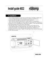
KEY
Y - Cooling
R - 24 VAC Power
W - Heating
Gt - Fan to Thermostat
Gf - Fan to Furnace
C - Common
V - Vent
Air Handler
AirCycler
® FRV
Thermostat
Damper
Blue
Red
White
WIRING DIAGRAM

4
www.aircycler.com
INSTALLATION INSTRUCTIONS
1.0 CONTROLLER LOCATION
The AirCycler® can be installed anywhere in your home. It can be installed near a thermostat or out of view on/near the
air handler unit. The wiring conguration is exible.
Warning: Before installing the AirCycler®, turn o all power to the furnace. There may be more than one power to dis-
connect. Electrical shock can cause injury or death.
2.0 INSTALLING THE AIRCYCLER®
1. Remove the AirCycler® cover from wall plate
(mounting base) to expose mounting holes.
(Figure 3)
2. Route wires through large hole in the mount-
ing base. Mount base against wall and mark
wall through 3 mounting holes.
3. Drill 3 - 3/16-in. pilot holes in wall where
marked.
4. Secure mounting base to wall with 3 screws
(provided), making sure all wires extend
through hole in mounting base.
5. Adjust length and routing of each wire to
reach proper terminal and connector block on
mounting base with 1/4 in. of extra wire. Strip
only 1/4 in. of insulation from each wire to
prevent adjacent wires from shorting together
when connected.
6. Connect wires to proper terminals of the con-
nector block. (Figure 3) Both (R) and (C) must
be connected for proper operation.
7. Improper wiring or installation may damage the controller. Check
to make sure wiring is correct before proceeding with installa-
tion or turning on the unit.
8. Push any excess wire into wall and against mounting base.
9. Snap cover onto base, making sure pins align with sockets in
connector.
10. Once powered on, the AirCycler® will automatically enter into
operating mode.
3.0 CONFIGURATION
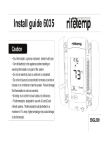
The three keys on the exterior of the AirCycler® are used to
congure the AirCycler®. (Figure 5)
The AirCycler® FRV has four settings.
Factory default settings: FAN OFF - 20 minutes; FAN ON - 10 minutes; VENT ON - 10 minutes; VENT OFF - 20 minutes
Figure 3

5
www.aircycler.com
3.1 CONFIGURE FAN ON TIME
Press the Mode Key once to enter the Menu Mode. FAN ON will ash on the display.
1. Use the Increase or Decrease Keys to change the FAN ON time from 1 - 199 minutes or to select unlimited ON
time (UN). UN allows the fan to operate continuously.
3.2 CONFIGURE FAN OFF TIME
1. Press the Mode Key again to set the FAN OFF time. FAN OFF will ash on the display.
2. Use the Increase or Decrease Keys to change the FAN OFF time or to select unlimited OFF time (UN). This will
turn o the AirCycler®. This will also keep the AirCycler® o even after power is lost.*
*The AirCycler® retains settings even after power is lost.
NOTE: In humid climates, the FAN OFF time should be at least 6 minutes. This allows moisture on the AC coil to dry
preventing condensation in cold supply ducts.
3.3 CONFIGURE VENT ON TIME
1. Press the Mode Key. VENT ON will ash.
2. Use the Increase or Decrease Keys to change the VENT ON time.
3.4 CONFIGURE VENT OFF TIME
1. Press the Mode Key. VENT OFF will ash.
2. Use the Increase or Decrease Keys to change the VENT OFF time.
3.5 SAVE SETTINGS
After conguring the AirCycler®, press the Mode Key again to save settings and to enter into Operating Mode.
Increase
Button
Mode Button
On/O
Decrease
Button
Figure 5

6
www.aircycler.com
4.0 OPERATING MODE
If the thermostat activates heating, cooling, or constant fan operation, the numeric display will read ON. Otherwise,
the display will read FAN OFF and will indicate the time remaining until the fan is activated again. Once activated, the
display will read FAN ON and the time remaining for FAN ON time.
The model FR-V has additional settings for outside air damper cycling. When the fan turns on, the damper will open and
the display will read VENT ON and indicate the time remaining until the damper closes. Once the VENT ON time has ex-
pired, the damper will close and the display will read VENT OFF and indicate the time remaining until the damper opens
again. This cycle continues for as long as the fan is running. The vent will be closed any time the fan is not running and
VENT ON and VENT OFF times will be reset to programmed values.
4.1 POWERING OFF
Warning: It is not recommended to turn o the AirCycler® if the unit is used as a ventilation controller. The AirCycler®
can be turned o during extended vacation periods or when the windows are open. It is very important to turn the Air-
Cycler® back on after those periods.
1. In normal Operating Mode: Press and hold the Mode Key for six seconds to turn o the AirCycler®. All thermostat
functions will continue to operate normally.
2. To turn the AirCycler® back on, press the Mode Key.
4.2 TESTING
The Test Mode will display fan activity in seconds rather than minutes. To activate Test Mode, follow these steps:
1. Press the Mode Key once and then press it again and hold for six seconds. The display will indicate TEST.
2. Exit Test Mode and return to Operating Mode by turning the AirCycler® o.
3. Hold the Mode Key for six seconds, and then press Mode again to turn on the AirCycler®.
NOTE: As a safeguard, the AirCycler® will automatically exit Test mode after ten minutes.

7
www.aircycler.com
5.0 TROUBLESHOOTING
Problem: Blank Display on the AirCycler®
Solution Check:
1. Conrm that the furnace has power.
2. Verify that the thermostat is operational.
3. Check that furnace will call for heat from the thermostat.
4. Ensure that fan operates with a fan-only signal from the thermostat
5. Conrm the furnace is providing a 24 VAC signal to the AirCycler®.
6. Verify that wiring conforms to wiring diagram.
7. Make sure top is rmly seated in the base.
Problem: AirCycler® FR-V turns furnace fan on and o, but the motorized damper does not cycle.
Solution Check:
1. Conrm that the AirCycler® is providing a 24 VAC signal to the motorized damper.
2. Verify that 24 VAC motorized damper is operational by powering directly with a 24 VAC signal.
3. Check continuity in the wiring between the damper and the AirCycler®.
Problem: A/C turns on during fan cycling calls
Solution Check:
1. Verify that wiring conforms to wiring diagram.
2. Ensure that the G wire is properly connected.
3. The G wire needs to be interrupted by the AirCycler®.
Do not run the G wire parallel.
Technical Support:
1.877.FAN.CONTrol
/