Novus NVIP-5VE-4202 Instrukcja obsługi
- Kategoria
- Kamery ochrony
- Typ
- Instrukcja obsługi

Q ui ck sta r t gu i de
NVIP-5VE-4202

NVIP-5VE-4202 Quick start guide ver. 1.0
All rights reserved © AAT Holding S.A.
2
IMPORTANT SAFEGUARDS AND WARNINGS
EMC (2014/30/UE) and LVD (2014/35/UE) Directives
CE Marking
Our products are manufactured to comply with the requirements of the following directives
and national regulations implementing the directives:
- Electromagnetic compatibility EMC 2014/30/UE.
- Low voltage LVD 2014/35/EC with further amendment. The Directive applies to electrical
equipment designed for use with a voltage rating of between 50VAC and 1000VAC as well as
75VDC and 1500VDC.
WEEE Directive 2012/19/UE
Information on Disposal for Users of Waste Electrical and Electronic Equipment
This appliance is marked according to the European Directive on Waste Electrical and
Electronic Equipment (2012/19/UE) and further amendments. By ensuring this product is
disposed of correctly, you will help to prevent potential negative consequences for the
environment and human health, which could otherwise be caused by inappropriate waste handling of
this product.
The symbol on the product, or the documents accompanying the product, indicates that this appliance
may not be treated as household waste. It shall be handed over to the applicable collection point for
used up electrical and electronic equipment for recycling purpose. For more information about
recycling of this product, please contact your local authorities, your household waste disposal service
or the shop where you purchased the product.
RoHS Directive 2011/65/UE
Information concerning the restriction of use of hazardous substances in electrical electronic
equipment.
Out of concern for human health protection and friendly environment, we assure that our
products falling under RoHS Directive regulations, regarding the restriction of the use of
hazardous substances in electrical and electronic equipment, have been designed and
manufactured in compliance with the above mentioned regulations. Simultaneously, we claim that our
products have been tested and do not contain hazardous substances whose exceeding limits could have
negative impact on human health or natural environment.
Information
The device, as a part of professional CCTV system used for surveillance and control, is not designed
for self installation in households by individuals without technical knowledge.
Excluding of responsibility in case of damaging data on a disk or other devices:
The manufacturer does not bear any responsibility in case of damaging or losing data on a disk or other
devices during device operation.
WARNING!
PRIOR TO UNDERTAKING ANY ACTION THAT IS NOT DESCRIBED FOR THE
GIVEN PRODUCT IN USER’S MANUAL AND OTHER DOCUMENTS DELIVERED
WITH THE PRODUCT, OR IF IT DOES NOT ARISE FROM THE USUAL
APPLICATION OF THE PRODUCT, MANUFACTURER MUST BE CONTACTED
UNDER THE RIGOR OF EXCLUDING THE MANUFACTURER’S RESPONSIBILITY

NVIP-5VE-4202 Quick start guide ver. 1.0
All rights reserved © AAT Holding S.A.
3
IMPORTANT SAFEGUARDS AND WARNINGS
WARNING!
THE KNOWLEDGE OF THIS MANUAL IS AN INDESPENSIBLE CONDITION OF A PROPER DEVICE
OPERATION. YOU ARE KINDLY REQUSTED TO FAMILIRIZE YOURSELF WITH THE MANUAL
PRIOR TO INSTALLATION AND FURTHER DEVICE OPERATION.
WARNING!
USER IS NOT ALLOWED TO DISASSEMBLE THE CASING AS THERE ARE NO USER-
SERVICEABLE PARTS INSIDE THIS UNIT. ONLY AUTHORIZED SERVICE PERSONNEL MAY OPEN
THE UNIT.
INSTALLATION AND SERVICING SHOULD ONLY BE DONE BY QUALIFIED SERVICE PERSONNEL
AND SHOULD CONFORM TO ALL LOCAL REGULATIONS.
IMPORTANT SAFEGUARDS AND WARNINGS
1. Prior to undertaking any action please consult the following manual and read all the safety and operating
instructions before starting the device.
2. Please keep this manual for the lifespan of the device in case referring to the contents of this manual is
necessary;
3. All the safety precautions referred to in this manual should be strictly followed, as they have a direct
influence on user’s safety and durability and reliability of the device;
4. All actions conducted by the servicemen and users must be accomplished in accordance with the user’s
manual;
5. The device should be disconnected from power sources during maintenance procedures;
6. Usage of additional devices and components neither provided nor recommended by the producer is forbidden;
7. Mounting the device in places where proper ventilation cannot be provided (e. g. closed lockers etc.) is not
recommended since it may lead to heat build-up and damaging the device itself as a consequence;
8. Mounting the camera on unstable surface or using not recommended mounts is forbidden. Improperly
mounted camera may cause a fatal accident or may be seriously damaged itself. The camera must be mounted
by qualified personnel with proper authorization, in accordance with this user’s manual.
9. Device should be supplied only from a power sources whose parameters are in accordance with those
specified by the producer in the camera technical datasheet. Therefore, it is forbidden to supply the camera
from a power sources with unknown parameters, unstable or not meeting producer’s requirements;
10. Signal cables (conducting TV or / and telemetric signal) should be placed in a way excluding the possibility
of damaging them by accident. Special attention must be paid to cables getting from the camera and
connecting the power supply;
11. To avoid equipment damage, whole TV circuit should be equipped with properly made discharge-, overload-
and lightning protection devices. Usage of separating transformers is advised;
12. Electric installation supplying the device should be designed to meet the specifications given by the producer
in such a way that overloading is impossible;
13. User cannot repair or upgrade the equipment himself. All maintenance actions and repairs should be
conducted only by qualified service personnel;
14. Unplug the camera from the power source immediately and contact the proper maintenance department
when the following occurs:
• Damages to the power cord or to the plug itself;
• Liquids getting inside the device or exposure to strong mechanical shock;
• Device behaves in a way not described in the manual and all adjustments approved by the
manufacturer and possible to apply by user himself, seem not to have any effect;
• Camera or its casing is damaged;
• Atypical behaviour of the camera components can be seen (heard).
15. In necessity of repairs attention to using only original replacement parts (with their parameters in accordance
with those specified by the producer) should be paid. Non-licensed service and non-genuine replacement
parts may cause fire or electric shock.

NVIP-5VE-4202 Quick start guide ver. 1.0
All rights reserved © AAT Holding S.A.
4
TABLE OF CONTENTS ..................................................................................................... 4
1. FOREWORD INFORMATION ................................................................................... ..5
1.1. General characteristics ......................................................................................... 5
1.2. Technical specification .................................................................................... ...6
1.3. Camera dimension ........................................................................................... ...7
1.4. Package contents ............................................................................................... ...7
2. START-UP AND INITIAL CONFIGURATION ......................................................... 8
2.1. Description of connectors .................................................................................... 8
2.2. Connecting ethernet cable ................................................................................... 8
2.3. Camera mounting ................................................................................................ 9
2.4. Starting the IP camera ........................................................................................ 10
2.5. Initial configuration via web browser ................................................................ 11
2.6. Security recommendations for network architecture and configuration ........... 12
3. NETWORK CONNECTION UTILIZING WEB BROSWER ................................ 13
3.1. Recommended PC specification for web browser ............................................. 13
3.2. Connection with IP camera via web browser ..................................................... 13
4. USING AND CONFIGURING ..................................................................................... 15
4.1. Remote Preview Interface. ................................................................................. 15
5. ELECTRIC CONNECTORS ...................................................................................... 17
5.1. Connecting power supply to the camera. .......................................................... 17
6. RESTORING FACTORY DEFAULTS ..................................................................... 17
6.1. Restore factory defaults via web browser .......................................................... 17
TABLE OF CONTENTS

NVIP-5VE-4202 Quick start guide ver. 1.0
All rights reserved © AAT Holding S.A.
5
1. FOREWORD INFORMATION
1.1. General Characteristics
• Sensor resolution: 5 megapixels
• Mechanical IR cut filter, IR operation capability
• Min. Illumination from 0 lx with IR LED on
• Wide Dynamic Range (WDR) for enhanced image quality in diverse light conditions
• Digital Noise Reduction (DNR)
• Lens type: varifocal, f=2.8 ~ 12mm/F=1.6
• Built-in LED illuminator: 40 pcs LED
• Compression: H.264/H265
• Max video processing resolution: 2592x1944
• Multi streaming: two independently configurable streams
• Stream parameters: compression, resolution, speed and quality defined individually for each
video stream
• RTP/RTSP protocol support for video transmission
• Hardware motion detection
• Hardware sabotage detection (lens shade)
• Built-in webserver: camera configuration through the website
• Wide range of responses to alarm events: e-mail with attachment, saving file on FTP server
• Four privacy zones
• Eight definable Region of Interest
• Power supply: 12VDC, PoE (Power over Ethernet 802.3af)
Information
Depending on the type of recorder/registration system, the range of features and options may vary. Full
list of camera functionality available from a given type of recorder is included in the compatibility table
on www.novuscctv.com/en
Information!
The manufacturer reserves the right to printing errors and technical specifications changes
without prior notice.
FOREWORD INFORMATION

NVIP-5VE-4202 Quick start guide ver. 1.0
All rights reserved © AAT Holding S.A.
6
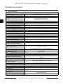
1.2. Technical specification
FOREWORD INFORMATION
Image
Image Sensor 5 MPX CMOS sensor 1/2.7” Smartsens
Number of Eecve Pixels 2592 (H) x 1944 (V)
Min. Illuminaon
0.06 lx/F1.6 - color mode,
0 lx (IR on) - B/W mode
Electronic Shuer auto/manual: 1/5 s ~ 1/20000 s
Digital Slow Shuer (DSS) up to 1/5 s
Wide Dynamic Range (WDR) yes
Digital Noise Reducon (DNR) 2D, 3D
Defog Funcon (F-DNR) yes
Kompensacja tylnego światła (BLC) yes
Lens
Lens Type varifocal, f=2.8 ~ 12 mm/F1.6
Day/Night
Switching Type mechanical IR cut lter
Switching Mode auto, manual
Switching Delay 1 ~ 36 s
Visible Light Sensor yes
Network
Stream Resoluon
2592 x 1944, 2592 x 1520, 2304 x 1296, 2048 x 1536, 1920 x 1080
(Full HD), 1280 x 960, 1280 x 720 (HD), 640 x 480 (VGA), 320 x 240
(QVGA)
Frame Rate
15 fps for 2592 x 1944,
20 fps for 2592 x 1520,
30 fps for 2048 x 1536 and lower resoluons
Mulstreaming Mode 2 streams
Video/Audio Compression H.264, H.265/-
Number of Simultaneous Connecons max. 10
Bandwidth 8 Mb/s in total
Network Protocols Support
HTTP, TCP/IP, IPv4, FTP, DHCP, DNS, DDNS, NTP, RTSP, RTP, UPnP,
SMTP
ONVIF Protocol Support Prole S/G
Camera Conguraon
from Internet Explorer browser
languages: Polish, English, Russian, and others
Compable Soware NMS
Other funcons
Privacy Zones 4
Moon Detecon yes
Region of interest (ROI) 8
Image Processing 180˚ image rotaon, vercal ip, horizontal ip
System Reacon to Alarm Events e-mail with aachment, saving le on FTP server

NVIP-5VE-4202 Quick start guide ver. 1.0
All rights reserved © AAT Holding S.A.
7
FOREWORD INFORMATION
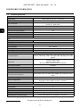
1.3. Camera dimensions
Dimensions are given in millimeters
1.4. Package contents
After you open the package make sure that the following elements are inside:
• IP camera
• Accessories bag
• Short version of user’s manual
CAUTION!
If the device was brought from a location with lower temperature, please wait until it reaches
the temperature of location it is currently in. Turning the device on immediately after bringing it
from a location with lower ambient temperature is forbidden, as the condensing water vapour
may cause short-circuits and damage the device as a result.
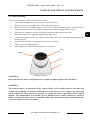
Before starting the device familiarize yourself with the description and the role of particular
inputs, outputs and adjusting elements that the device is equipped with.
IR LED
LED Number 40
Range 40 m
Angle 120°
Interfaces
Network Interface 1 x Ethernet - RJ-45 interface, 10/100 Mbit/s
Installaon parameters
Dimensions (mm) 135 (Ф) x 128 (H)
Weight 0.7 kg
Degree of Protecon IP 66 (details in the user’s manual, page 9)
Enclosure vandal proof aluminium, white
Power Supply PoE, 12 VDC
Power Consumpon 2 W, 6 W (IR on)
Operang Temperature -30°C ~ 55°C

NVIP-5VE-4202 Quick start guide ver. 1.0
All rights reserved © AAT Holding S.A.
8
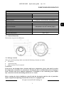
1
2
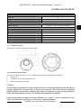
2. START-UP AND INITIAL CONFIGURATION
2.1. Description of connectors
1. Power supply 12VDC
2. 100 Mb/s Ethernet port (RJ-45 hermetic connector)
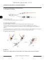
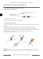
2.2. Connecting ethernet cable
To maintain tightness of ethernet cable connection, please follow instruction below:
1. Unscrew the nut (b) from the connector cover (a), mount the sealing ring on the socket (c)
2. Route the network cable through the components (a) and (b). Plug the RJ-45 connector into the
socket (c)
3. Screw the connector cover (a) on the socket (c). Inside the upper part of the connector cover (a) push
in to the stop the seal of the cable (d) - the seal is cut to insert on the network cable.
4. Tighten up to the stop nut (b)
WARNING!
Camera power supply connector is not hermetic. User should seal this connector by himself.
START-UP AND INITIAL CONFIGURATION
b a
b
a
c
d

NVIP-5VE-4202 Quick start guide ver. 1.0
All rights reserved © AAT Holding S.A.
9
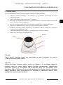
2.3. Camera mounting
To mount a camera please follow the instructions below:
• Unscrew the locking ring (A) by turning it counter-clockwise
• Remove the camera cover (B), remove the camera from the base
• Put the bracket or mounting template to the wall in a desired mounting place (with cable hole).
Taking the bracket’s base screw holes as a pattern, mark future drilling holes for screws.
• Drill holes in accordance with previously done markings and base hole placement.
• Mount the camera base using the supplied plugs and screws.
• Connect the camera cables, put camera on the base, attach the cover (B) and pre-tighten the
locking ring (A)
• Adjust camera position, set appropriate field of view and focus
• Fully screw the locking ring (A)
• Make adjustments to the camera using the on-screen menu
WARNING!
Please note that the wall or ceiling must have enough strength to support the IP Camera.
WARNING!
The declared degree of protection of the camera relates to its housing and does not take into
account the possibility of moisture infiltration into the interior of the camera by connecting
cables. Connection cables protection through i.e. sealing up is the responsibility of the camera
installer. The manufacturer is not liable for any damages to the camera caused as a result of
failing in performing that activity by installer, which also means that camera damaged in that
way is not subject to warranty repairs.
START-UP AND INITIAL CONFIGURATION
Focus
Zoom
A
B

NVIP-5VE-4202 Quick start guide ver. 1.0
All rights reserved © AAT Holding S.A.
10
START-UP AND INITIAL CONFIGURATION
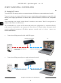
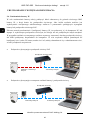
2.4. Starting the IP camera
To run NOVUS IP camera you have to connect ethernet cable between camera and network switch.
To power it up you can connect it directly via power supply adapter with parameters compatible with
camera power supply specification, or camera can be powered with PoE (IEEE 802.3af ) compatible
switch.
After connecting power supply it takes about 30 seconds to start camera. Then You can proceed to
connect to the camera via web browser.
The recommended way to start an IP camera and perform its configuration is a connection directly
to the network switch which is not connected to other devices. To obtain further information about
network configuration parameters (IP address, gateway, network mask, etc.) please contact your
network administrator.
• Connection utilising network switch with PoE support
• Connection utilising external power supply and network switch
PC
IP camera
Network transmission
Network PoE switch
Power supply and network
transmission
IP camera
Network transmission Network transmission
Network switch
PC

NVIP-5VE-4202 Quick start guide ver. 1.0
All rights reserved © AAT Holding S.A.
11
START-UP AND INITIAL CONFIGURATION
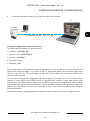
• Connection utilising external power supply directly to the computer
2.5. Initial configuration via the web browser
The default network settings for the camera are:
1. IP address= 192.168.1.200
2. Network mask - 255.255.255.0
3. Gateway - 192.168.1.1
4. User name - root
5. Password - pass
Knowing the camera’s IP address you need to appropriately set PC IP address, so the two devices can
operate in one network subnet ( e.g. for IP 192.168.1.1, appropriate address for the camera ranges from
192.168.1.2 to 192.168.1.254, for example 192.168.1.60). It is not allowed to set the same addresses for
camera and PC computer
You can either set a network configuration (IP address, gateway, net mask, etc.) of NOVUS IP camera
yourself or select DHCP mode (DHCP server is required in this method in target network) by using
web browser or by NMS software. When you use DHCP server check IP address lease and its linking
with camera MAC address to avoid changing or losing IP address during device operation or network/
DHCP server breakdown. You have to remember to use a new camera IP address after changing
network parameters.
After network setting configuration has been done, the camera can be connected to a target network.
IP Camera
Network transmission - cross over cable
PC

NVIP-5VE-4202 Quick start guide ver. 1.0
All rights reserved © AAT Holding S.A.
12
START-UP AND INITIAL CONFIGURATION
2.6 Security recommendations for network architecture and configuration
WARNING!
Below are shown security recommendations for network architecture and configuration
of CCTV systems that are connected to the Internet to reduce the risk
of unauthorized interference with the system by a third party.
1. Absolutely change the default passwords and user names (if the device gives this possibility) of
all applied network devices (recorders, cameras, routers, network switches, etc.) to the
severely complexity password. Use lowercase and uppercase letters, numbers, and special characters
if there is such possibility.
2. Depending on the available functionality in the order to restrict access to the used network devices at
the administrator account level, it is recommended to configure the users accounts accordingly.
3. Do not use DMZ function (Demilitarized zone) in your router. Using that function you open the
access to recorder system from the Internet on all ports, which gives possibility for an unauthorized
interference with the system.
Instead of DMZ use port forwarding redirect only the ports which are necessary for the performance
of the connection (detailed information about ports of communication in different models of recorders,
cameras, etc. can be found in the operating instructions).
4. Use routers with firewall function and make sure it is enabled and properly configured.
5. It is recommended to change the default network communication port numbers of used devices
if there is such possibility.
6. If used network devices has a UPnP feature and it is not used, turn it off.
7. If used network devices has a P2P feature and it is not used, turn it off.
8. If used network devices support HTTPS protocol for connection, it is recommended to use it.
9. If used network devices support IP filtering for authorized connections function, it is recommended
to use it.
10. If used recorder has two network interfaces it is recommended to use both of them to physically
separate network for cameras and network for Internet connection. The only device in the system,
accessible from Internet will be recorder - there will be no physically access directly to any camera.

NVIP-5VE-4202 Quick start guide ver. 1.0
All rights reserved © AAT Holding S.A.
13
NETWORK CONNECTION USING WEB BROWSER
3. NETWORK CONNECTION USING WEB BROSWER
3.1. Recommended PC specification for web browser connections
Requirements below apply to connection with an IP camera, assuming smooth image display
in 2592x1944 resolution and 15 fps speed.
1. CPU Intel Core i3 3GHz or newer
2. RAM Memory min. 4 GB
3. Graphic card NVIDIA GeForce 1 GHz
4. OS Windows VISTA / 7 / 8
5. Network card 10/100/1000 Mb/s
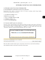
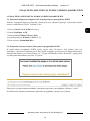
3.2. Connection with IP camera via web browser
You have to enter camera IP address in the address bar. When you connect to the camera, web browser
will download the applet for displaying images from the camera. In Internet Explorer before the first
logon you need to install „SurveillancePlugin.exe” addition. To do this, please click on the link
„Download” and when you get the download window, click „Run” button.
When the addition installer window appears, temporarily close the browser and click "Install" button.
After installation, launch a web browser and connect to the camera.

NVIP-5VE-4202 Quick start guide ver. 1.0
All rights reserved © AAT Holding S.A.
14
If the installation fails, changing security settings for the IE browser is required. In order to do that,
please choose: Tools > Internet options > Security tab > Custom level and:
• Under Download unsigned ActiveX controls - select either Enable or Prompt
• Under Initialize and script ActiveX controls not marked as safe - select Enable or Prompt
You can also add the camera’s IP address to “trusted zone” and set lowest security level for it.
In addition, when working in Windows Vista / 7 / 8 the ActiveX applet may be blocked by Windows
Defender or User account control. In such case you should allow to run this applet, or simply disable
these functions.
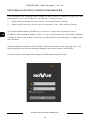
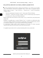
When the addition is installed it will be possible to log into the camera. On the login page, enter your
login information. Here can also change the language of the camera interface can be maid.
For safety reasons, we recommend to change the default password and user name.
NETWORK CONNECTION UTILIZING WEB BROWSER

NVIP-5VE-4202 Quick start guide ver. 1.0
All rights reserved © AAT Holding S.A.
15
4. USING AND CONFIGURING
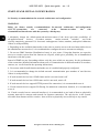
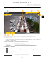
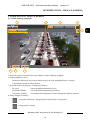
4.1. The Remote Preview Interface
1. The selection buttons to select the stream to be displayed in the Remote Preview window.
2. Live Preview window.
Double-clicking the left mouse button on the preview window enables and disables the display of
the image on the full screen.
3. Buttons for selecting the operating mode and configure the camera:
Live - Enables preview live stream
Remote Setting - displays the configuration panel camera
Local Setting - displays the configuration panel of paths to snapshots folders
4. Icon to access to the camera:
USING AND CONFIGURING
- displays information about the logged in user and the version of the applet
- logout from the camera
6
8
7
3
4
5
1
2

NVIP-5VE-4202 Quick start guide ver. 1.0
All rights reserved © AAT Holding S.A.
16
USING AND CONFIGURING
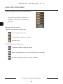
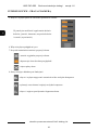
5. Enable/disable panel to set the image parameters:
The panel is the ability to adjust the hue,
brightness, contrast, color saturation and
Sharpness.
6. Enable/disable live preview
7. Buttons to set the size and aspect ratio:
8. Additional features control icons:
- sets the original aspect ratio
- fits the image to the browser window
- sets full screen
- enables and disables enlarge the picture
- enables and disables the record a video stream on your computer
- performs a screenshot and saves on your computer

NVIP-5VE-4202 Quick start guide ver. 1.0
All rights reserved © AAT Holding S.A.
17
ELECTRIC CONNECTORS AND RESTORING FACTORY DEFAULTS
5. ELECTRIC CONNECTORS
5.1. Connecting power supply to the camera.
Camera can be supplied using external power supply unit corresponding with the camera parameters or
by using RJ45 network socket and PoE (802.3af) power supply unit.
Information:
Power supply adapter is not included. Please use power adapter with parameters specified in user’s
manual.
WARNING!
It is forbidden to use – as the camera power source – PoE equipment (adapters, etc.) not
compatible with IEEE 802.3af standard (items called “passive PoE power supply”). Damages that
results from the usage of improper power supply source are not covered by the warranty.
WARNING!
In order to provide protection against voltage surges/lightning strikes, usage of appropriate surge
protectors is advised. Any damages resulting from surges are not eligible for service repairs.
6. RESTORING FACTORY DEFAULTS
6.1. Restoring factory defaults
The camera allows you to reset your settings to the factory values. To restore the camera settings to the
default, go to the "Load Default" tab (Remote Setting -> Advanced -> Load Default). Then select options
and functions of the camera whose settings are to be reset and press the "Save" button. After about 30
seconds, you can re-connect to the camera (at the current IP address, as long as it was not reset network
settings or on the default IP address).
Information
A description of all functions of the camera is included in the full user manual, posted on the product
page on www.novuscctv.com/en

AAT Holding S.A.
431 Pulawska St., 02-801 Warsaw, Poland
tel.: +4822 546 07 00, fax: +4822 546 07 59
www.novuscctv.com
7.06.2019 TF, v1.0

Sk r ó co n a i n s tr uk c j a o bs ł ug i
NVIP-5VE-4202

NVIP-5VE-4202 Skrócona instrukcja obsługi wersja 1.0
Wszelkie prawa zastrzeżone © AAT Holding S.A.
2
UWAGI I OSTRZEŻENIA
Dyrektywy EMC (2014/30/UE) i LVD (2014/35/UE)
Oznakowanie CE
Nasze produkty spełniają wymagania zawarte w dyrektywach oraz przepisach krajowych
wprowadzających dyrektywy:
Kompatybilność elektromagnetyczna EMC 2014/30/UE.
Niskonapięciowa LVD 2014/35/UE. Dyrektywa ma zastosowanie do sprzętu elektrycznego
przeznaczonego do użytkowania przy napięciu nominalnym od 50VAC do 1000VAC oraz od 75VDC do
1500VDC.
Dyrektywa WEEE 2012/19/UE
Informacja dla użytkowników o pozbywaniu się urządzeń elektrycznych i elektronicznych
Niniejszy produkt został oznakowany zgodnie z Dyrektywą WEEE (2012/65/UE) oraz
późniejszymi zmianami, dotyczącą zużytego sprzętu elektrycznego
i elektronicznego. Zapewniając prawidłowe złomowanie przyczyniają się Państwo
do ograniczenia ryzyka wystąpienia negatywnego wpływu produktu na środowisko i
zdrowie ludzi, które mogłoby zaistnieć w przypadku niewłaściwej utylizacji urządzenia.
Symbol umieszczony na produkcie lub dołączonych do niego dokumentach oznacza,
że nasz produkt nie jest klasyfikowany jako odpad z gospodarstwa domowego. Urządzenie należy oddać
do odpowiedniego punktu utylizacji odpadów w celu recyklingu. Aby uzyskać dodatkowe informacje
dotyczące recyklingu niniejszego produktu należy skontaktować się
z przedstawicielem władz lokalnych, dostawcą usług utylizacji odpadów lub sklepem, gdzie nabyto
produkt.
Dyrektywa RoHS 2011/65/UE
Informacja dla użytkowników dotycząca ograniczenia użycia substancji niebezpiecznych w sprzęcie
elektrycznym elektronicznym.
W trosce o ochronę zdrowia ludzi oraz przyjazne środowisko zapewniamy, że nasze
produkty podlegające przepisom dyrektywy RoHS, dotyczącej użycia substancji
niebezpiecznych w sprzęcie elektrycznym i elektronicznym, zostały zaprojektowane
i wyprodukowane zgodnie z wymaganiami tej dyrektywy. Jednocześnie zapewniamy, że
nasze produkty zostały przetestowane i nie zawierają substancji niebezpiecznych
w ilościach mogących niekorzystnie wpływać na zdrowie człowieka lub środowisko naturalne.
Informacja
Urządzenie, jako element profesjonalnego systemu telewizji dozorowej służącego do nadzoru i kontroli,
nie jest przeznaczone do samodzielnego montażu w gospodarstwach domowych przez osoby nie
posiadające specjalistycznej wiedzy.
Wyłączenie odpowiedzialności w przypadku uszkodzenia danych zawartych na dysku lub innych
urządzeniach:
Producent nie ponosi odpowiedzialności w razie uszkodzenia lub utraty w trakcie eksploatacji Produktu
danych zawartych na dyskach lub innych urządzeniach.
Obowiązek konsultowania się z Producentem przed wykonaniem czynności
nieprzewidzianej instrukcją obsługi albo innymi dokumentami:
Przed wykonaniem czynności, która nie jest przewidziana dla danego Produktu w instrukcji
obsługi, innych dokumentach dołączonych do Produktu lub nie wynika ze zwykłego
przeznaczenia Produktu, należy, pod rygorem wyłączenia odpowiedzialności Producenta za
następstwa takiej czynności, skontaktować się z Producentem.
Strona się ładuje...
Strona się ładuje...
Strona się ładuje...
Strona się ładuje...
Strona się ładuje...
Strona się ładuje...
Strona się ładuje...
Strona się ładuje...
Strona się ładuje...
Strona się ładuje...
Strona się ładuje...
Strona się ładuje...
Strona się ładuje...
Strona się ładuje...
Strona się ładuje...
Strona się ładuje...
-
 1
1
-
 2
2
-
 3
3
-
 4
4
-
 5
5
-
 6
6
-
 7
7
-
 8
8
-
 9
9
-
 10
10
-
 11
11
-
 12
12
-
 13
13
-
 14
14
-
 15
15
-
 16
16
-
 17
17
-
 18
18
-
 19
19
-
 20
20
-
 21
21
-
 22
22
-
 23
23
-
 24
24
-
 25
25
-
 26
26
-
 27
27
-
 28
28
-
 29
29
-
 30
30
-
 31
31
-
 32
32
-
 33
33
-
 34
34
-
 35
35
-
 36
36


Novus NVIP-5VE-4202 Instrukcja obsługi
- Kategoria
- Kamery ochrony
- Typ
- Instrukcja obsługi
w innych językach
- English: Novus NVIP-5VE-4202 User manual
Powiązane artykuły
-
Novus NVIP-2V-4202 Instrukcja obsługi
-
-
-
-
-
-
-
-
-