AAT NVIP-12F-8001 Instrukcja obsługi
- Kategoria
- Kamery ochrony
- Typ
- Instrukcja obsługi
Niniejsza instrukcja jest również odpowiednia dla

User’ s ma n ual
(shor t for m )
NVIP-12F-8001

NVIP-12F-8001, User’s manual (short) ver.1.0
All rights reserved © AAT Holding S.A.
2
IMPORTANT SAFEGUARDS AND WARNINGS
EMC (2014/30/EU) and LVD (2014/35/EU) Directives
CE Marking
Our products are manufactured to comply with requirements of the following directives and national
regulations implementing the directives:
• Electromagnetic compatibility EMC 2014/30/EU.
• Low voltage LVD 2014/35/EU with further amendment. The Directive applies to electrical
equipment designed for use with a voltage rating of between 50VAC and 1000VAC as well as
75VDC and 1500VDC.
WEEE WEEE 2012/19/UE
Information on Disposal for Users of Waste Electrical and Electronic Equipment
This appliance is marked according to the European 1000VAC Directive on Waste Electrical and
Electronic Equipment (2012/19/UE) and further amendments. By ensuring this product is disposed of
correctly, you will help to prevent potential negative consequences for the environment and human
health, which could otherwise be caused by inappropriate waste handling of this product.
The symbol on the product, or the documents accompanying the product, indicates that this appliance may not be
treated as household waste. It shall be handed over to the applicable collection point for used up electrical and
electronic equipment for recycling purpose. For more information about recycling of this product, please contact
your local authorities, your household waste disposal service or the shop where you purchased the product.
RoHS Directive 2011/65/UE
Out of concern for human health protection and friendly environment, we assure that our products falling under
RoHS Directive regulations, regarding the restriction of the use of hazardous substances in electrical and
electronic equipment, have been designed and manufactured in compliance with the above mentioned
regulations. Simultaneously, we claim that our products have been tested and do not contain hazardous
substances whose exceeding limits could have negative impact on human health or natural
environment
Information
The device, as a part of professional CCTV system used for surveillance and control, is not
designed for self installation in households by individuals without technical knowledge.
Excluding of responsibility in case of damaging data on a disk or other devices:
The manufacturer does not bear any responsibility in case of damaging or losing data on a disk or other devices
during device operation.
WARNING!
PRIOR TO UNDERTAKING ANY ACTION THAT IS NOT DESCRIBED FOR THE GIVEN PRODUCT IN
USER’S MANUAL AND OTHER DOCUMENTS DELIVERED WITH THE PRODUCT, OR IF IT DOES
NOT ARISE FROM THE USUAL APPLICATION OF THE PRODUCT, MANUFACTURER MUST BE
CONTACTED UNDER THE RIGOR OF EXCLUDING THE MANUFACTURER’S RESPONSIBILITY FOR
THE RESULTS OF SUCH AN ACTION.

NVIP-12F-8001, User’s manual (short) ver.1.0
All rights reserved © AAT Holding S.A.
3
IMPORTANT SAFEGUARDS AND WARNINGS
WARNING!
THE KNOWLEDGE OF THIS MANUAL IS AN INDISPENSIBLE CONDITION OF A PROPER
DEVICE OPERATION. YOU ARE KINDLY REQEUSTED TO FAMILIARIZE YOURSELF WITH
THE MANUAL PRIOR TO INSTALLATION AND FURTHER DEVICE OPERATION.
WARNING!
USER IS NOT ALLOWED TO DISASSEMBLE THE CASING AS THERE ARE NO USER
-SERVICEABLE PARTS INSIDE THIS UNIT. ONLY AUTHORIZED SERVICE PERSONNEL
MAY OPEN THE UNIT
INSTALLATION AND SERVICING SHOULD ONLY BE DONE BY QUALIFIED SERVICE
PERSONNEL AND SHOULD CONFORM TO ALL LOCAL REGULATIONS
1. Prior to undertaking any action please consult the following manual and read all the safety and operating
instructions before starting the device.
2. Please keep this manual for the lifespan of the device in case referring to the contents of this manual is
necessary;
3. All the safety precautions referred to in this manual should be strictly followed, as they have a direct
influence on user’s safety and durability and reliability of the device;
4. All actions conducted by the servicemen and users must be accomplished in accordance with the user’s
manual;
5. The device should be disconnected from power sources during maintenance procedures;
6. Usage of additional devices and components neither provided nor recommended by the producer is
forbidden;
7. You are not allowed to use the camera in high humidity environment (i.e. close to swimming pools, bath tubs,
damp basements);
8. Mounting the device in places where proper ventilation cannot be provided (e. g. closed lockers etc.) is not
recommended since it may lead to heat build-up and damaging the device itself as a consequence;
9. Mounting the camera on unstable surface or using not recommended mounts is forbidden. Improperly
mounted camera may cause a fatal accident or may be seriously damaged itself. The camera must be mounted
by qualified personnel with proper authorization, in accordance with this user’s manual.
10. Device should be supplied only from a power sources whose parameters are in accordance with those
specified by the producer in the camera technical datasheet. Therefore, it is forbidden to supply the camera
from a power sources with unknown parameters, unstable or not meeting producer’s requirements;
Due to the product being constantly enhanced and optimized, certain parameters and functions described in the
manual in question may change without further notice. We strongly suggest visiting the www.novuscctv.com
website in order to access the newest manual
Data included in the following user’s manual is up to date at the time of printing. AAT Holding S.A. holds
exclusive rights to modify this manual. The producer reserves the rights for device specification modification
and change in the design without prior notice.

NVIP-12F-8001, User’s manual (short) ver.1.0
All rights reserved © AAT Holding S.A.
4
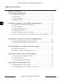
TABLE OF CONTENTS ..................................................................................................... 4
1. FOREWORD INFORMATION ................................................................................... ..5
1.1. General Characteristics ........................................................................................ 5
1.2. Specification .................................................................................................... ...6
1.3. Camera dimension ........................................................................................... ...7
1.4. Package contents ............................................................................................... ...8
2. START-UP AND INITIAL IP CAMERA CONFIGURATION ................................. 9
2.1. Description of connectors and control tools ........................................................ 9
2.2 Camera mounting ............................................................................................... 10
2.3. Connecting Ethernet cable ................................................................................. 11
2.4. Starting the IP camera ........................................................................................ 12
2.5. Initial configuration via the Web browser ......................................................... 13
2.6. Security recommendations for network architecture and configuration............ 14
3. NETWORK CONNECTION UTILIZING WEB BROSWER ................................ 15
3.1. Recommended PC specification for web browser ............................................. 15
3.2. Connection with IP camera via web browser ..................................................... 15
4. WWW INTERFACE - WORKING WITH IP CAMERA ......................................... 18
4.1. Displaying live pictures. ..................................................................................... 18
4.2. Adding a site to the Compatibility View list ..................................................... 19
5. ELECTRIC CONNECTORS AND ACCESORIES ................................................. 19
5.1. Connecting power supply to the camera. .......................................................... 19
5.2. SD card installation ............................................................................................ 20
5.3. Connecting alarm input and output ................................................................... 20
6. RESTORING FACTORY DEFAULTS ..................................................................... 21
6.1. Restoring software factory defaults .................................................................... 21
6.2. Restoring hardware factory defaults in IP cameras ........................................... 21
TABLE OF CONTENTS

NVIP-12F-8001, User’s manual (short) ver.1.0
All rights reserved © AAT Holding S.A.
5
1. FOREWORD INFORMATION
1.1. General Characteristics
• Imager resolution: 12.0 megapixels
• Mechanical IR cut filter
• IR operation capability
• Min. Illumination from 0.04 lx/F=2.4
• Wide Dynamic Range (WDR)
• Digital Slow Shutter (DSS)
• Digital Noise Reduction (DNR)
• Defog Function (F-DNR)
• Digital Image Stabilization (DIS)
• Highlight Compensation (HLC)
• Lens type: fish eye lens, f=1.8mm, F=2.4
• Built-in IR illuminator, 6 LEDs
• 1 Alarm input and 1 alarm output
• Compression: H.264, H.265, M-JPEG
• Max video processing resolution: 4000x3000
• Multi streaming: individually defined compression, resolution, speed and quality
• RTP/RTSP protocol support for video transmission
• Built-in microphone
• Pre & post-alarm functions
• Built-in webserver: camera configuration through the website
• MicroSD card support to 128GB
• Wide range of responses to alarm events: e-mail with attachment, saving file on FTP server,
saving file on SD card, alarm output activation
• Network protocol support : HTTP, TCP/IP, IPv4, UDP, HTTPS, Multicast, FTP, DHCP, DNS,
NTP, RTSP, RTP, UPnP, IEEE 802.1X, PPPoE, SMTP, RTCP
• Software: NMS (NOVUS MANAGEMENT SYSTEM) for video recording, live monitoring,
playback and remote IP devices administration
• Enclosure vandal proof IK10
• Built-in Heater
• Power supply: 12VDC, 24VAC, PoE (Power over Ethernet)
FOREWORD INFORMATION

NVIP-12F-8001, User’s manual (short) ver.1.0
All rights reserved © AAT Holding S.A.
6
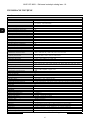
1.2. Specification
FOREWORD INFORMATION
Image
Image Sensor 12 MPX CMOS sensor 1/1.7” SONY Exmor R STARVIS
Number of Effective Pixels 4072 (H) x 3046 (V)
Min. Illumination
0.04 lx/F2.4 - color mode,
0 lx (IR on) - B/W mode
Electronic Shutter auto: 1/5 s ~ 1/20000 s
Digital Slow Shutter (DSS) up to 1/5 s
Wide Dynamic Range (WDR) yes
Digital Image Stabilization (DIS) yes
Digital Noise Reduction (DNR) 2D, 3D
Defog Function (F-DNR) yes
Highlight Compensation (HLC) yes
Lens
Lens Type fisheye, f=1.8 mm/F2.4
Day/Night
Switching Type mechanical IR cut filter
Switching Mode auto, manual, time
Switching Level Adjustment yes
Switching Delay 0 ~ 180 s
Switching Schedule yes
Visible Light Sensor yes
Network
Stream Resolution
4000 x 3000, 4096 x 2160, 3840 x 2160 (4K Ultra HD), 3000 x 3000, 2560 x 2560,
1920 x 1080 (Full HD), 1280 x 960, 720 x 720, 704 x 576
Frame Rate
20 fps for 4000 x 3000,
25 fps for 4096 x 2160 and lower resolutions
Multistreaming Mode 2 streams
Video/Audio Compression H.264, H.265, MJPEG/G.711, RAW_PCM
Number of Simultaneous Connections max. 8
Bandwidth 30 Mb/s in total
Network Protocols Support
HTTP, TCP/IP, IPv4, UDP, HTTPS, Multicast, FTP, DHCP, DNS, NTP, RTSP, RTP, UPnP,
IEEE 802.1X, PPPoE, SMTP, RTCP
ONVIF Protocol Support Profile S
Camera Configuration
from Internet Explorer browser
languages: Polish, English, Russian, and others
Compatible Software NMS
Other functions
Privacy Zones 4
Motion Detection yes
Region of interest (ROI) 8
Image Processing 180˚ image rotation, mirror effect
Prealarm/Postalarm up to 5 MB/up to 86400 s
System Reaction to Alarm Events e-mail with attachment, saving file on FTP server, saving file on SD card, alarm output activation
IR LED
LED Number 6
Range 10 m
Angle 180°
Interfaces
Audio Input/Output 1 x RCA/1 x RCA built-in microphone,
Alarm Input/Output 1 (NO/NC)/1
Network Interface 1 x Ethernet - RJ-45 interface, 10/100 Mbit/s
Memory Card Slot microSD - capacity up to 128GB
Installation parameters
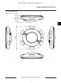
Dimensions (mm) 162 (Ф) x 52 (H)
Weight 0.7 kg
Degree of Protection IP 66 (details in the user’s manual)
Enclosure vandalproof IK10 impact rating aluminium, white poly-carbonate bubble
Power Supply PoE, 12 VDC/24 VAC
Power Consumption 3.7 W, 9.5 W (IR on), 5.7 W (heater on), 11.5 W (IR and heater on)
Operating Temperature -30°C ~ 60°C
Built-in Heater/Fan yes/no

NVIP-12F-8001, User’s manual (short) ver.1.0
All rights reserved © AAT Holding S.A.
7
FOREWORD INFORMATION
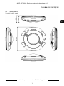
1.3. Camera dimensions
All dimensions are in mm

NVIP-12F-8001, User’s manual (short) ver.1.0
All rights reserved © AAT Holding S.A.
8
1.4. Package contents
After you open the package make sure that the following elements are inside:
• IP camera
• 230 VAC / 12 VDC power supply
• Accessories bag
• Short version of user’s manual
• CD containing manual and software
If any of this elements has been damaged during transport, pack all the elements back into the original
box and contact your supplier for further assistance.
CAUTION!
If the device was brought from a location with lower temperature, please wait until it reaches the
temperature of location it is currently in. Turning the device on immediately after bringing it
from a location with lower ambient temperature is forbidden, as the condensing water vapour
may cause short-circuits and damage the device as a result.
Before starting the device familiarize yourself with the description and the role of particular
inputs, outputs and adjusting elements that the device is equipped with.
1.4. Package contents
After you open the package make sure that the following elements are inside:
• IP camera
• Accessories bag
• Short version of user’s manual
If any of this elements has been damaged during transport, pack all the elements back into the original
box and contact your supplier for further assistance.
Caution:
If the device was brought from a location with lower temperature, please wait until it reaches the
temperature of location it is currently in. Turning the device on immediately after bringing it
from a location with lower ambient temperature is forbidden, as the condensing water vapour
may cause short-circuits and damage the device as a result.
Before starting the device familiarize yourself with the description and the role of particular
inputs, outputs and adjusting elements that the device is equipped with.
Caution:
In order to provide protection against voltage surges/lightning strikes, usage of appropriate surge
protectors is advised. Any damages resulting from surges are not eligible for service repairs.
Caution:
It is forbidden to use – as the camera power source – PoE equipment (adapters, etc.) not compatible
with IEEE 802.3af standard (items called “passive PoE power supply”). Damages that results from
the usage of improper power supply source are not covered by the warranty.
Caution:
Camera connectors / sockets are not hermetic. The user should ensure their hermeticity on his
own.
Caution:
Please note that the wall or ceiling must have enough strength to support the IP Camera.
Caution:
In order to obtain declared degree of protection please seal the camera base to prevent water
getting inside. Furthermore, when installing the camera on rough/uneven surfaces, please
additionally seal the junction with appropriate sealing mass. Please pay special attention to any
mounting holes and if they are a loop-through ones, seal them too.
Caution:
The declared degree of protection of the camera relates to its housing and does not take into account
the possibility of moisture infiltration into the interior of the camera by connecting cables.
Connection cables protection through i.e. sealing up is the responsibility of the camera installer. The
manufacturer is not liable for any damages to the camera caused as a result of failing in performing
that activity by installer, which also means that camera damaged in that way is not subject to
warranty repairs.
FOREWORD INFORMATION

NVIP-12F-8001, User’s manual (short) ver.1.0
All rights reserved © AAT Holding S.A.
9
2. START-UP AND INITIAL IP CAMERA CONFIGURATION
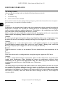
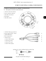
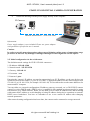
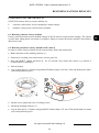
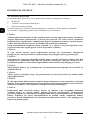
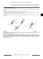
2.1. Description of connectors and control tools
1. Network connection indicator
2. Power connection indicator
3. MicroSD card indicator
4. Rest button
6. MicroSD card slot
1. 100 Mb/s Ethernet port (RJ-45)
2. Power supply 12VDC / 24VAC
3. Audio input (RCA)
4 Audio output (RCA)
5. Alarm IN/OUT
• Alarm COM0 (orange)
• Alarm IN0 (yellow)
• Alarm OUT1 (gray)
• Alarm COM1 (purple)
START-UP AND INITIAL CAMERA CONFIGURATION
SCHEMA OF 12VDC POWER SUPPLY CONNECTOR

NVIP-12F-8001, User’s manual (short) ver.1.0
All rights reserved © AAT Holding S.A.
10
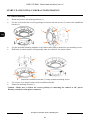
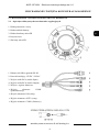
2.2. Camera mounting
• Rotate and remove the masking element (1).
• Use the L-wrench in the accessory package to unscrew the star screws (2), remove the installation
bracket (3).
• Use the included mounting template or the camera base plate to mark holes for mounting screws.
• Drill holes in marked places and optionally make an extra hole for camera cables.
• Mount the installation bracket (3) using included mounting screws.
• Use screws (2) to mount camera to the installation bracket.
• Mount the masking element (1).
Caution : Make sure to follow the correct polarity if connecting the camera to DC power.
Polarity is marked on the power connector.
START-UP AND INITIAL CAMERA CONFIGURATION
2
2
2
2
3
1
3
2
2
2
2
1

NVIP-12F-8001, User’s manual (short) ver.1.0
All rights reserved © AAT Holding S.A.
11
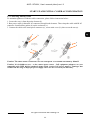
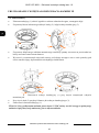
2.3. Connecting Ethernet cable
To maintain tightness of Ethernet cable connection, please follow instruction below:
1. Loosen the nut (a) from the main element (b).
2. Run power cable (without RJ-45 connector) though both elements. Then crimp the cable with RJ-45
connector. Install rubber gasket (d) on the connector (c).
3. Connect the cable to the waterproof connector (c), screw main cover (b), then screw the nut (a).
Caution: The other camera connectors are not waterproof. User should seal them by himself.
Caution: It is forbidden to use – as the camera power source – PoE equipment (adapters, etc.) not
compatible with IEEE 802.3af standard (items called “passive PoE power supply”). Damages that
results from the usage of improper power supply source are not covered by the warranty.
a
b
a
b
c
d
START-UP AND INITIAL CAMERA CONFIGURATION

NVIP-12F-8001, User’s manual (short) ver.1.0
All rights reserved © AAT Holding S.A.
12
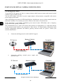
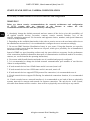
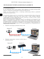
2.4. Starting the IP camera
To run NOVUS IP camera you have to connect ethernet cable between camera and network switch
with PoE support (IEEE 802.3af).
You can also connect it directly via power supply adapter with parameters compatible with camera
power supply specification.
After connecting power status red LED should light on. Initialization process is then started which can
take about 2 minutes. You can then proceed to connect to the camera via web browser.
If the connection is successfully established green network status LED blinks with a frequency
proportional to the quantity of data sent.
The recommended way to start an IP camera and perform its configuration is a connection directly
to the network switch which is not connected to other devices. To obtain further information about
network configuration parameters (IP address, gateway, network mask, etc.) please contact your
network administrator.
• Connection utilising network switch with PoE support
• Connection utilising external power supply and
network switch
START-UP AND INITIAL CAMERA CONFIGURATION
Power supply and
network transmission
Computer IP Camera
Network Switch
PoE
Network transmission
IP Camera
Network transmission
Network Switch
Computer
Network transmission

NVIP-12F-8001, User’s manual (short) ver.1.0
All rights reserved © AAT Holding S.A.
13
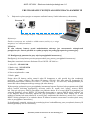
• Connection utilising external power supply directly to the computer
Information:
Power supply adapter is not included. Please use power adapter
with parameters specified in user’s manual.
Caution:
In order to provide protection against voltage surges/lightning strikes, usage of appropriate surge
protectors is advised. Any damages resulting from surges are not eligible for service repairs.
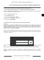
2.5. Initial configuration via the web browser
The default network settings for NVIP-12F-8001 camera are :
1. IP address= 192.168.1.200
2. Network mask - 255.255.255.0
3. Gateway - 192.168.1.1
4. User name - root
5. Password - pass
Knowing the camera’s IP address you need to appropriately set PC IP address, so the two devices can
operate in one network subnet ( e.g. for IP 192.168.1.1, appropriate address for the camera ranges from
192.168.1.2 to 192.168.1.254, for example 192.168.1.60). It is not allowed to set the same addresses for
camera and PC computer
You can either set a network configuration (IP address, gateway, net mask, etc.) of NOVUS IP camera
yourself or select DHCP mode (DHCP server is required in this method in target network) by using
web browser or by NMS software. When you use DHCP server check IP address lease and its linking
with camera MAC address to avoid changing or losing IP address during device operation or network/
DHCP server breakdown. You have to remember to use a new camera IP address after changing
network parameters.
After network setting configuration has been done, the camera can be connected to a target network.
START-UP AND INITIAL CAMERA CONFIGURATION
IP Camera
Network transmission - cross over cable
Computer

NVIP-12F-8001, User’s manual (short) ver.1.0
All rights reserved © AAT Holding S.A.
14
2.6. Security recommendations for network architecture and configuration
WARNING!
Below are shown security recommendations for network architecture and configuration
of CCTV systems that are connected to the Internet to reduce the risk
of unauthorized interference with the system by a third party.
1. Absolutely change the default passwords and user names (if the device gives this possibility) of
all applied network devices (recorders, cameras, routers, network switches, etc.) to the
severely complexity password. Use lowercase and uppercase letters, numbers, and special characters
if there is such possibility.
2. Depending on the available functionality in the order to restrict access to the used network devices at
the administrator account level, it is recommended to configure the users accounts accordingly.
3. Do not use DMZ function (Demilitarized zone) in your router. Using that function you open the
access to recorder system from the Internet on all ports, which gives possibility for an unauthorized
interference with the system.
Instead of DMZ use port forwarding redirect only the ports which are necessary for the performance
of the connection (detailed information about ports of communication in different models of recorders,
cameras, etc. can be found in the operating instructions).
4. Use routers with firewall function and make sure it is enabled and properly configured.
5. It is recommended to change the default network communication port numbers of used devices
if there is such possibility.
6. If used network devices has a UPnP feature and it is not used, turn it off.
7. If used network devices has a P2P feature and it is not used, turn it off.
8. If used network devices support HTTPS protocol for connection, it is recommended to use it.
9. If used network devices support IP filtering for authorized connections function, it is recommended
to use it.
10. If used recorder has two network interfaces it is recommended to use both of them to physically
separate network for cameras and network for Internet connection. The only device in the system,
accessible from Internet will be recorder - there will be no physically access directly to any camera.
START-UP AND INITIAL CAMERA CONFIGURATION

NVIP-12F-8001, User’s manual (short) ver.1.0
All rights reserved © AAT Holding S.A.
15
NETWORK CONNECTION UTILIZING WEB BROWSER
3. NETWORK CONNECTION VIA WEB BROSWER
3.1. Recommended PC specification for web browser connections
Requirements below apply to connection with an IP camera, assuming image display in 4000 x 3000
resolution and 20 fps speed.
1. CPU Intel i5 3 GHz or faster
2. RAM Memory min. 4 GB
3. VGA card (any displaying Nvidia GeForce 512MB Ram memory)
4. OS Windows 7 / 8 / 10
5. Network card 100/1000 Mb/s
3.2. Connection with IP camera via web browser
Caution:
To maintain correct operation as snapshot or video recording you must enable the browser as an
administrator, also to maintain correct operation as playback from the microSD card you must
add IP camera address to Compatibility View in browser settings.
You have to enter camera IP address in the web browser address bar. If IP address is correct user login
window will be displayed:
Default user is root and default password is pass.
In the Language box you can change the display language. The default language is English.
For safety reasons, it is recommended to change default user name and password.

NVIP-12F-8001, User’s manual (short) ver.1.0
All rights reserved © AAT Holding S.A.
16
NETWORK CONNECTION VIA WEB BROWSER
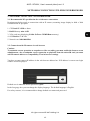
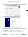
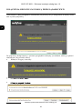
If you’re first time running the camera, you will see screen as below.
To correctly camera working, you need a plugin, you have to download and install it as below.
• Click Download and setup and follow the prompts.
Download and setup
Download and setup

NVIP-12F-8001, User’s manual (short) ver.1.0
All rights reserved © AAT Holding S.A.
17
NETWORK CONNECTION VIA WEB BROWSER
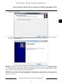
• Click Install button
• After installation, click Finished button
Caution: In Windows Vista/7/8/10 the ActiveX applet may be blocked by Windows Defender or
User account control. In such case you should allow to run this applet, or simply disable these
functions.
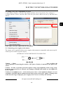
Caution: If the installation fails, changing security settings for the IE browser is required. In order to do
that, please choose: Tools > Internet options > Security tab > Custom level and:
• Under Download unsigned ActiveX controls - select either Enable or Prompt
• Under Initialize and script ActiveX controls not marked as safe - select Enable or Prompt

NVIP-12F-8001, User’s manual (short) ver.1.0
All rights reserved © AAT Holding S.A.
18
WWW INTERFACE - WORKING WITH IP CAMERA
4. WWW INTERFACE - WORKING WITH IP CAMERA
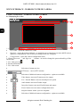
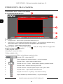
4.1. Displaying live video
1. Camera menu:
• Live Video - opens the camera live video
• Playback - opens the camera playback - to maintain correct operation you must add IP camera
address to Compatibility View in browser settings (look at 4.2 chapter)
• Configuration - opens the camera configuration menu
2. Change Password and Sign out buttons - are used to change the password and log off the
current user.
3. Live video preview
4. Stream information
5. Live video menu
• Selection of stream preview
• PTZ button - turn on PTZ window
• Selection of additional camera configuration - option not available
• Video button- turn-on/off camera preview output
• Live / Smooth Button- turn-on smooth preview option
• Audio button- turn-on/off audio output
• Interphone button- turn-on/off audio input and output
• Sensor button- turn-on sensor configuration menu
• Snapshot button- make a preview snapshot
• Selection of additional camera configuration - option not available
1.
3.
4.
5.
2.

NVIP-12F-8001, User’s manual (short) ver.1.0
All rights reserved © AAT Holding S.A.
19
ELECTRIC CONNECTORS AND ACCESORIES
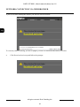
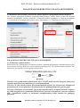
4.2 Adding a site to the Compatibility View list
1. Open Internet Explorer, select the Tools button and then select Compatibility View settings (1).
2. Under Add this website, enter the URL of the site you want to add to the list (2), and then select
Add (3).
5.
ELECTRIC CONNECTORS AND ACCESORIES
5.1. Connecting power supply to the camera.
The camera can be supplied only by power supplay with parameters compatible with camera specifi-
cation to power camera via power in jack.
SCHEMA OF 12VDC POWER SUPPLY CONNECTOR
Caution : Make sure to follow the
correct polarity if connecting the camera to DC power. Polarity is marked on the power con-
nector.
Caution: In order to provide protection against voltage surges/lightning strikes, usage of ap-
propriate surge protectors is advised. Any damages resulting from surges are not eligible for
service repairs.
Caution: It is forbidden to use – as the camera power source – PoE equipment (adapters, etc.) not
compatible with IEEE 802.3af standard (items called “passive PoE power supply”). Damages that
results from the usage of improper power supply source are not covered by the warranty.
1.
2.
3.

NVIP-12F-8001, User’s manual (short) ver.1.0
All rights reserved © AAT Holding S.A.
20
ELECTRIC CONNECTORS AND ACCESORIES
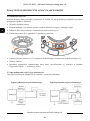
5.2. SD card installation
Camera supports micro SD, cards with their capacity up to 128GB. In order to install the card properly,
please follow the instructions below:
• Turn the camera off.
• Rotate and remove the masking element (1).
• Unscrew two locking screws and remove service panel (2).
• Mount microSD card in the socket (3), according to the picture:
• Mount service
panel (2) and two locking screws. Mount the masking element (1).
• Turn the camera on.
• Check the SD card by checking it in the Device Record -> Record Directory tab.
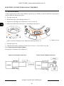
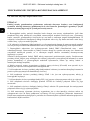
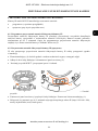
5.3. Connecting alarm inputs/outputs.
Description of connectors is in chapter 2.1.
Typical Alarm Input connection Typical Alarm Output connection
1
2
3
Strona się ładuje...
Strona się ładuje...
Strona się ładuje...
Strona się ładuje...
Strona się ładuje...
Strona się ładuje...
Strona się ładuje...
Strona się ładuje...
Strona się ładuje...
Strona się ładuje...
Strona się ładuje...
Strona się ładuje...
Strona się ładuje...
Strona się ładuje...
Strona się ładuje...
Strona się ładuje...
Strona się ładuje...
Strona się ładuje...
Strona się ładuje...
Strona się ładuje...
Strona się ładuje...
Strona się ładuje...
Strona się ładuje...
Strona się ładuje...
-
 1
1
-
 2
2
-
 3
3
-
 4
4
-
 5
5
-
 6
6
-
 7
7
-
 8
8
-
 9
9
-
 10
10
-
 11
11
-
 12
12
-
 13
13
-
 14
14
-
 15
15
-
 16
16
-
 17
17
-
 18
18
-
 19
19
-
 20
20
-
 21
21
-
 22
22
-
 23
23
-
 24
24
-
 25
25
-
 26
26
-
 27
27
-
 28
28
-
 29
29
-
 30
30
-
 31
31
-
 32
32
-
 33
33
-
 34
34
-
 35
35
-
 36
36
-
 37
37
-
 38
38
-
 39
39
-
 40
40
-
 41
41
-
 42
42
-
 43
43
-
 44
44


AAT NVIP-12F-8001 Instrukcja obsługi
- Kategoria
- Kamery ochrony
- Typ
- Instrukcja obsługi
- Niniejsza instrukcja jest również odpowiednia dla
w innych językach
- English: AAT NVIP-12F-8001 User manual
Powiązane artykuły
-
Novus NVIP-6DN3618V/IR-1P Instrukcja obsługi
-
-
-
-
-
-
-
-
-