Hotpoint Ariston PK 741 RQO GH /HA EE Operating Instructions Manual
- Kategoria
- Płyty
- Typ
- Operating Instructions Manual

PK 741 RQO GH /HA EE
English
Operating Instructions
HOB
Contents
Operating Instructions,1
Warnings,2
Assistance,5
Description of the appliance,6
Installation,9
Start-up and use,13
Precautions and tips,14
Maintenance and care,15
Troubleshooting,15
Polski
Instrukcja obsługi
PŁYTA
Magyar
Használati útmutató
FŐZŐLAP
Spis treści
Instrukcja obsługi,1
Ostrzezenia,2
Serwis Techniczny,5
Opis urządzenia,6
Instalacja,16
Uruchomienie i użytkowanie,20
Zalecenia i środki ostrożności,21
Konserwacja i utrzymanie,22
Anomalie i środki zaradcze,23
Česky
Pokyny pro použití
VARNÁ DESKA
Slovensky
Návod na použitie
VARNÁ DOSKA
Obsah
Pokyny pro použití,1
Upozornění,3
Servisní služba,5
Popis zařízení,7
Instalace,24
Uvedení do činnosti a použití,28
Opatření a rady,29
Údržba a péče,30
Identikace a řešení problémů,30
Obsah
Návod na použitie,1
Upozornenia,3
Servisná služba,5
Popis zariadenia,7
Inštalácia,32
Uvedenie do činnosti a použitie,36
Opatrenia a rady,37
Údržba a starostlivosť,38
Identikácia a riešenie problémov,38
Tartalomjegyzék
Használati útmutató,1
Figyelmeztetések,4
Szerviz,5
A készülék leírása,8
Beszerelés,40
Bekapcsolás és használat,44
Óvintézkedések és tanácsok,45
Karbantartás és ápolás,46
Hibaelhárítás,46

2
Warnings
WARNING: The appliance and its accessible parts
become hot during use. Care should be taken to
avoid touching heating elements. Children less than 8
years of age shall be kept away unless continuously
supervised. This appliance can be used by children
aged from 8 years and above and persons with
reduced physical, sensory or mental capabilities or
lack of experience and knowledge if they have been
given supervision or instruction concerning use of the
appliance in a safe way and understand the hazards
involved. Children shall not play with the appliance.
Cleaning and user maintenance shall not be made
by children without supervision.
WARNING: Unattended cooking on a hob with fat or
oil can be dangerous and may result in re. NEVER
try to extinguish a re with water, but switch off the
appliance and then cover ame e.g. with a lid or a
re blanket.
WARNING: Danger of re: do not store items on the
cooking surfaces.
WARNING: If the surface in glass-ceramic is cracked,
switch off the appliance to avoid the possibility of
electric shock.
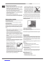
Never use steam cleaners or pressure cleaners on
the appliance.
Remove any liquid from the lid before opening it. Do
not close the glass cover (if present) when the gas
burners or electric hotplates are still hot.
The appliance is not intended to be operated by
means of an external timer or separate remote
control system.
CAUTION: the use of inappropriate hob guards can
cause accidents.
CAUTION: In case of hotplate glass breakage:
- shut immediately off all burners and any electrical
heating element and isolate the appliance from the
power supply
- do not touch the appliance surface.
Ostrzezenia
UWAGA: To urządzenie oraz jego dostępne części
silnie się rozgrzewają podczas użytkowania. Należy
uważać, aby nie dotknąć elementów grzejnych.
Nie pozwalać, aby dzieci poniżej 8 roku życia
zbliżały się do urządzenia, jeśli nie są pod stałym
nadzorem dorosłych. Z niniejszego urządzenia
mogą korzystać dzieci powyżej 8 roku życia i
osoby o ograniczonych zdolnościach zycznych,
zmysłowych bądź umysłowych, jak również osoby
nieposiadające doświadczenia lub znajomości
urządzenia, jeśli znajdują się one pod nadzorem
innych osób lub jeśli zostały pouczone na temat
bezpiecznego sposobu użycia urządzenia oraz
zdają sobie sprawę ze związanych z nim zagrożeń.
Dzieci nie powinny bawić się urządzeniem. Prace
związane z czyszczeniem i konserwacją nie mogą
być wykonywane przez dzieci, jeśli nie są one
nadzorowane.
UWAGA: Pozostawienie bez nadzoru na kuchence
tłuszczów i olejów może być niebezpieczne i może
spowodować pożar. Nie należy NIGDY próbować
ugasić płomieni/pożaru wodą; należy wyłączyć
urządzenie i przykryć płomień np. pokrywką lub
ognioodpornym kocem.
UWAGA: Ryzyko pożaru: nie pozostawiać
przedmiotów na powierzchniach grzejnych.
UWAGA: Jeżeli powierzchnia ze szkła ceramicznego
jest pęknięta, należy wyłączyć urządzenie, aby
uniknąć niebezpieczeństwa porażenia prądem
elektrycznym.
Nie stosować nigdy oczyszczaczy parowych lub
ciśnieniowych do czyszczenia urządzenia.

3
Usunąć ewentualne płyny na pokrywie przed jej
otwarciem. Nie zamykać szklanej pokrywy (jeśli jest
częścią wyposażenia), jeśli palniki gazowe lub płyta
elektryczna są jeszcze rozgrzane.
Urządzenie nie jest przeznaczone do włączania przy
użyciu zewnętrznego przekaźnika czasowego lub
zdalnego systemu sterowania.
UWAGA: użycie niewłaściwych zabezpieczeń płyty
może być przyczyną wypadków.
UWAGA: W przypadku uszkodzenia szkła płyty:
- wyłączyć natychmiast wszystkie palniki i ewentualne
elementy grzejne i odłączyć urządzenie od sieci
elektrycznej
- nie dotykać powierzchni urządzenia.
Upozornění
VÝSTRAHA: Zařízení a jeho přístupné součásti
se mohou během použití zahřát. Dávejte pozor,
abyste se nedotkli horkých prvků. Děti mladší 8
let musí být udržovány v bezpečné vzdálenosti
nebo musí být nepřetržitě pod dohledem. Toto
zařízení mohou používat děti nad 8 let a osoby s
omezenými fyzickými, senzorickými nebo duševními
schopnostmi nebo s nedostatečnými zkušenostmi
pouze v případě, že jsou pod dohledem nebo byly
náležitě poučeny ohledně bezpečného použití
zařízení a pochopily související nebezpečí. Děti si
nesmí se zařízením hrát. Čištění a údržbu svěřenou
uživateli nesmí provádět děti bez dohledu.
VÝSTRAHA: Nepozornost při vaření na varné desce
s tukem nebo olejem může být nebezpečná a může
způsobit požár. NIKDY se nepokoušejte hasit oheň
vodou, ale vypněte zařízení a přikryjte plameny např.
víkem nebo hasicí rouškou.
VÝSTRAHA: Nebezpečí požáru! Neskladujte
předměty na varných površích!
VÝSTRAHA: Když je sklokeramický povrch prasknutý,
vypněte zařízení, aby se zabránilo možnosti zásahu
elektrickým proudem.
Nikdy nepoužívejte k čištění zařízení parní nebo
vysokotlaký čistič.
Před otevřením víka z něj odstraňte veškeré tekutiny.
Nezavírejte skleněný kryt (je-li součástí), když jsou
hořáky nebo elektrické plotny ještě horké.
Zařízení není určeno k použití prostřednictvím
externích časovačů nebo samostatného systému
dálkového řízení.
UPOZORNĚNÍ: použití nevhodných ochranných
krytů varné desky může způsobit nehodu.
UPOZORNĚNÍ: V případě prasknutí skla varné
desky:
- okamžitě vypněte všechny hořáky a jakákoli
elektrická topná tělesa a odizolujte zařízení od
napájení,
- nedotýkejte se povrchu zařízení.
Upozornenia
VÝSTRAHA: Zariadenie a jeho prístupné časti sa
môžu počas použitia ohriať. Dávajte pozor, aby ste
sa nedotkli horúcich častí. Deti mladšie ako 8 rokov
musia byť udržiavané v bezpečnej vzdialenosti,
alebo musia byť nepretržite pod dohľadom. Toto
zariadenie môžu používať deti nad 8 rokov a osoby
s obmedzenými fyzickými, zmyslovými alebo
duševnými schopnosťami, alebo s nedostatočnými
skúsenosťami, len ak sú pod dohľadom, alebo ak
boli náležite poučené ohľadne bezpečného použitia
zariadenia a ak pochopili možné nebezpečenstvá.
Deti sa nesmú so zariadením hrať. Čistenie a
údržbu zverenú užívateľovi nesmú vykonávať deti
bez dohľadu.
VÝSTRAHA: Nepozornosť pri varení na varnej doske
s tukom alebo olejom môže byť nebezpečná a môže
spôsobiť požiar. NIKDY sa nepokúšajte hasiť oheň

4
vodou, ale vypnite zariadenie a prikryte plamene,
napr. vekom alebo hasiacou utierkou.
VÝSTRAHA: Nebezpečenstvo požiaru! Nenechávajte
predmety na varných povrchoch.
VÝSTRAHA: Keď je sklokeramický povrch prasknutý,
vypnite zariadenie, aby nedošlo k zásahu elektrickým
prúdom.
Nikdy nepoužívajte na čistenie zariadenia parný
alebo vysokotlakový čistič.
Pred otvorením veka z neho odstráňte všetky
tekutiny. Nezatvárajte sklenený kryt (ak je súčasťou),
keď sú horáky alebo elektrické platne ešte teplé.
Zariadenie nie je vhodné na ovládanie prostredníctvom
externých časovačov alebo samostatného systému
diaľkového riadenia.
UPOZORNENIE: použitie nevhodných ochranných
krytov varnej dosky môže spôsobiť nehodu.
UPOZORNENIE: V prípade prasknutia skla varnej
dosky:
- okamžite vypnite všetky horáky a akékoľvek
elektrické výhrevné telesá a odpojte zariadenie
z elektrickej siete,
- nedotýkajte sa povrchu zariadenia.
Figyelmeztetések
FIGYELMEZTETÉS: A készülék és a hozzáférhető
részei felforrósodnak a használat során. Ügyeljen
rá, hogy ne érjen a fűtőelemekhez. A 8 évnél
atalabb gyermekeket távol kell tartani, ha nincsenek
folyamatos felügyelet alatt. Ezt a berendezést
használhatják 8 évnél idősebb gyermekek és
csökkent zikai, szenzoros vagy mentális képességű,
illetve tapasztalattal és tudással nem rendelkező
személyek, ha felügyelet alatt álnak, vagy ha
megfelelő útmutatást kaptak a készülék biztonságos
működtetéséről, valamint megértették a fennálló
veszélyeket. A gyermekek nem játszhatnak a
készülékkel. A tisztítást és a felhasználó által
elvégezhető karbantartást nem végezhetik felügyelet
nélküli gyermekek.
FIGYELMEZTETÉS: Veszélyes lehet, ha a bekapcsolt
főzőlapon őrizetlenül hagyja a zsírt vagy az olajat,
mert tüzet okozhat. SOHA ne próbálja vízzel eloltani a
tüzet, hanem kapcsolja le a készüléket, majd takarja
le a lángot pl. egy fedővel vagy tűzálló kendővel.
FIGYELMEZTETÉS: Tűzveszély: ne tároljon semmit
a főzőfelületen.
FIGYELMEZTETÉS: Ha a kerámiaüveg felület
repedt, kapcsolja le a készüléket, hogy elkerülje a
lehetséges áramütést.
A készülék tisztításához soha ne használjon
gőztisztítót vagy nagynyomású tisztítót.
Mielőtt felemeli a tetőt, törölje le róla a rajta lévő
esetleges nedvességet. Ne csukja le az üvegfedőt,
(ha van ilyen), ha a gázégők meg vannak gyújtva
vagy még melegek.
A készüléket nem külső időzítő vagy külön távirányító
berendezéssel együtt történő használatra tervezték.
VIGYÁZAT: a nem megfelelő főzőlap védők
használata balesetet okozhat.
VIGYÁZAT: Amennyiben a főzőlap üvege eltörne:
- azonnal kapcsoljon ki minden égőt és bármilyen
elektromos fűtőegységet és válassza le a készüléket
az elektromos hálózatról
- ne érintse meg a készülék felületét.

5
Assistance
Communicating:
• type of trouble
• appliance model (Mod.)
• serial number (S/N)
This information is found on the data plate located on the appliance and/or
on the packaging.
Serwis Techniczny
Należy podać:
• rodzaj anomalii
• model urządzenia (Mod.)
• numer seryjny (S/N)
Te dane znajdują się na tabliczce znamionowej umieszczonej na urządzeniu
i/lub na opakowaniu.
Servisní služba
Když se obrátíte na servisní službu, oznamte:
• typ poruchy,
• model zařízení (Mod.),
• výrobní číslo (S/N).
Tyto informace se nacházejí na identifikačním štítku, umístěném na zařízení,
a/nebo na obalu.
Servisná služba
Keď sa obrátite na servisnú službu, oznámte:
• typ poruchy,
• model zariadenia (Mod.),
• výrobné číslo (S/N).
Tieto informácie sa nachádzajú na identifikačnom štítku, umiestnenom na
zariadení a/alebo na obale.
Szerviz
Kommunikáció:
• a típusú anomália
• a készülék típusa (mod.)
• a készülék sorozatszáma (s/n)
Ezek az adatok a készüléken és/vagy a csomagoláson elhelyezett adattáblán
található meg.

6
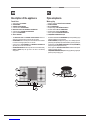
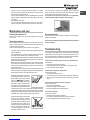
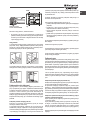
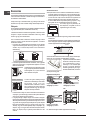
Description of the appliance
Overall view
1. Support Grid for COOKWARE
2. GAS BURNERS
3. CERAMIC GLASS MODULE
4. Control Knobs for GAS BURNERS
5. INDICATOR LIGHT FOR CERAMIC GLASS MODULE
6. Control Knobs for CERAMIC GLASS MODULE
7. Ignition for GAS BURNERS
8. SAFETY DEVICES
• The INDICATOR LIGHT for CERAMIC GLASS MODULE switches on
whenever the selector knob is moved from the ‘off’ position.
• GAS BURNERS differ in size and power. Use the diameter of the cookware
to choose the most appropriate burner to cook with.
• Control Knobs for GAS BURNERS and CERAMIC GLASS MODULE
adjust the power or the size of the ame.
• GAS BURNER IGNITION enables a specic burner to be lit automatically.
• SAFETY DEVICE stops the gas flow if the flame is accidentally
extinguished.
Opis urządzenia
Widok ogólny
1. Ruszty do ustawiania NACZYŃ DO GOTOWANIA
2. PALNIKI GAZOWE
3. PŁYTA CERAMICZNA
4. Pokrętła sterujące PALNIKÓW GAZOWYCH
5. Kontrolka działania PŁYTY CERAMICZNEJ
6. Pokrętła sterujące PŁYTY CERAMICZNEJ
7. Świeca zapłonowa PALNIKÓW GAZOWYCH
8. URZĄDZENIA ZABEZPIECZAJĄCE
• Kontrolka działania PŁYTY CERAMICZNEJ zapala się dla każdej pozycji
pokrętła z wyjątkiem pozycji wyłączenia.
• PALNIKI GAZOWE posiadają różne wymiary i moce. Należy wybrać ten
palnik, który jest najbardziej odpowiedni dla średnicy używanego naczynia.
• Pokrętła sterowania PALNIKAMI GAZOWYMI oraz PŁYTĄ CERAMICZĄ
służą do regulowania płomienia lub mocy.
• Świeca zapłonowa PALNIKÓW GAZOWYCH umożliwia automatyczne
zapalenie wybranego palnika.
• URZĄDZENIE ZABEZPIECZAJĄCE w razie przypadkowego zgaśnięcia
płomienia przerywa dopływ gazu.
8
7
1
4
2
3
6
5

7
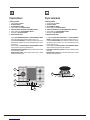
Popis zařízení
Celkový pohled
1. Opěrná mřížka pro HRNCE
2. PLYNOVÉ HOŘÁKY
3. SKLOKERAMICKÝ MODUL
4. Otočné ovládače pro PLYNOVÉ HOŘÁKY
5. SVĚTELNÝ INDIKÁTOR PRO SKLOKERAMICKÝ MODUL
6. Otočné ovladače pro SKLOKERAMICKÝ MODUL
7. Zapalování pro PLYNOVÉ HOŘÁKY
8. BEZPEČNOSTNÍ PRVKY
• K zapnutí SVĚTELNÉHO INDIKÁTORU pro SKLOKERAMICKÝ MODUL
dochází při každém pohybu otočného ovladače z polohy ‘vyp.’.
• Jednotlivé PLYNOVÉ HOŘÁKY se vzájemně liší velikostí a výkonem. Na
základě průměru použitých hrnců zvolte nejvhodnější hořák pro vaření v
těchto hrncích.
• Otočné ovladače pro PLYNOVÉ HOŘÁKY a SKLOKERAMICKÝ MODUL
slouží k nastavení výkonu nebo velikosti plamene.
• ZAPÁLENÍ PLYNOVÉHO HOŘÁKU aktivuje specifický hořák za účelem
jeho automatického zapálení.
• BEZPEČNOSTNÍ PRVEK slouží k zastavení průtoku plynu v případě
náhodného zhašení plamene.
Popis zariadenia
Celkový pohľad
1. Oporná mriežka pre HRNCE
2. PLYNOVÉ HORÁKY
3. SKLOKERAMICKÝ MODUL
4. Otočné ovládače pre PLYNOVÉ HORÁKY
5. SVETELNÝ INDIKÁTOR SKLOKERAMICKÉHO MODULU
6. Otočné ovládače pre SKLOKERAMICKÝ MODUL
7. Zapaľovanie pre PLYNOVÉ HORÁKY
8. BEZPEČNOSTNÉ PRVKY
• K zapnutiu SVETELNÉHO INDIKÁTORA pre SKLOKERAMICKÝ
MODUL dochádza pri každom pohybe otočného ovládača z polohy ‘vyp.’.
• Jednotlivé PLYNOVÉ HORÁKY sa navzájom líšia veľkosťou a výkonom.
Na základe priemeru použitých hrncov zvoľte najvhodnejší horák pre
varenie v týchto hrncoch.
• Otočné ovládače pre PLYNOVÉ HORÁKY a SKLOKERAMICKÝ MODUL
slúžia na nastavenie výkonu alebo veľkosti plameňa.
• ZAPAĽOVAČ PLYNOVÉHO HORÁKA umožňuje automaticky zapáliť
daný horák.
• BEZPEČNOSTNÝ PRVOK slúži na zastavenie prietoku plynu v prípade
náhodného zhasnutia plameňa.
8
7
1
4
2
3
6
5

8
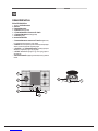
A készülék leírása
A készülék áttekintése
1. Tartórács a FŐZŐEDÉNYEKHEZ
2. GÁZÉGŐK
3. ÜVEGKERÁMIA MODUL
4. A GÁZÉGŐK szabályzógombjai
5. AZ ÜVEGKERÁMIA MODUL VISSZAJELZŐ LÁMPÁI
6. Az ÜVEGKERÁMIA MODUL szabályzógombjai
7. A GÁZÉGŐK gyújtója
8. BIZTONSÁGI ESZKÖZÖK
• A ÜVEGKERÁMIA MODUL VISSZAJELZŐ LÁMPÁJA világítani kezd,
ha a választókapcsolót elmozdítja „off” (ki) állásból.
• A GÁZÉGŐK mérete és teljesítménye eltérő. A főzőedény átmérője alapján
válassza ki a főzéshez leginkább megfelelő gázégőt
• A GÁZÉGŐK és az ÜVEGKERÁMIA MODUL szabályzógombjaival
állíthatja be a teljesítményt vagy a láng nagyságát.
• A GÁZÉGŐ GYÚJTÓJA segítségével egy adott égőt gyújthat be
automatikusan.
• A BIZTONSÁGI ESZKÖZ megállítja a gáz áramlását, ha a láng véletlenül
kialszik.
8
7
1
4
2
3
6
5

GB
9
Installation
! Before operating your new appliance please read this instruction booklet
carefully. It contains important information for safe use, installation and care
of the appliance.
! Please keep these operating instructions for future reference. Pass them on
to possible new owners of the appliance.
Positioning
! Keep packaging material out of the reach of children. It can become a choking
or suffocation hazard (see Precautions and tips).
! The appliance must be installed by a qualied professional according to the
instructions provided. Incorrect installation may cause harm to people and
animals or may damage property.
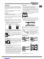
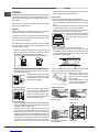
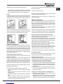
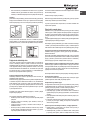
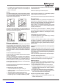
! This unit may be installed and used only in permanently ventilated rooms
in accordance with current national regulations. The following requirements
must be observed:
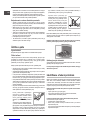
• The room must be equipped with an air extraction system that expels
any combustion fumes. This may consist of a hood or an electric fan that
automatically starts each time the appliance is switched on.
In a chimney stack or branched flue.
(exclusively for cooking appliances)
Directly to
the Outside
• The room must also allow proper air circulation, as air is needed for
combustion to occur normally. The ow of air must not be less than 2 m3/h
per kW of installed power.
The air circulation system may take air directly
from the outside by means of a pipe with an
inner cross section of at least 100 cm2; the
opening must not be vulnerable to any type
of blockages.
The system can also provide the air needed for
combustion indirectly, i.e. from adjacent rooms
tted with air circulation tubes as described
above. However, these rooms must not be
communal rooms, bedrooms or rooms that
may present a re hazard.
• Intensive and prolonged use of the appliance may necessitate
supplemental ventilation, e.g. opening a window or increasing the power
of the air intake system (if present).
• Liquid petroleum gas sinks to the oor as it is heavier than air. Therefore,
rooms containing LPG cylinders must also be equipped with vents to allow
gas to escape in the event of a leak. As a result LPG cylinders, whether
partially or completely full, must not be installed or stored in rooms or
storage areas that are below ground level (cellars, etc.). It is advisable to
keep only the cylinder being used in the room, positioned so that it is not
subject to heat produced by external sources (ovens, replaces, stoves,
etc. ) which could raise the temperature of the cylinder above 50°C.
A
Examples of
ventilation holes
for comburant air.
Enlarging the ventilation slot
between window and floor.
Adjacent
Room
Room to be
Vented
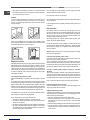
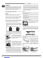
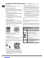
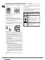
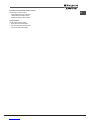
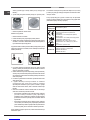
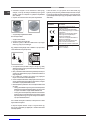
Fitting the appliance
The following precautions must be taken when installing the hob:
• Kitchen cabinets adjacent to the appliance and taller than the top of the
hob must be at least 200 mm from the edge of the hob.
• Hoods must be installed according to their relative installation instruction
manuals and at a minimum distance of 650 mm from the hob (see gure).
• Place the wall cabinets adjacent to the hood at a minimum height of 420
mm from the hob (see gure).
If the hob is installed beneath a wall cabinet,
the latter must be situated at a minimum of 700
mm above the hob.
• The installation cavity should have the dimensions indicated in the gure.
Fastening hooks are provided, allowing you to fasten the hob to tops that
are between 20 and 40 mm thick. To ensure the hob is securely fastened
to the top, we recommend you use all the hooks provided.
555 mm
55 mm
475 mm
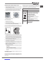
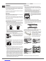
Before the installation remove the grids and burners from the hob and turn it
upside down, making sure you don’t damage the thermocouples and spark
plugs.
Apply the seals that come with the
appliance along the outer edges of
the hob to prevent any passage of air,
humidity and water (see Figure).
For proper application make sure the
surfaces to be sealed are clean, dry and
free of any grease/oil.
Hook fastening diagram
Hooking position Hooking position
for top H=20mm for top H=30mm
Front
Hooking position Back
for top H=40mm
! Use the hooks contained in the “accessory pack”.
600mm min.
420mm min.
650mm min.

10
GB
• Where the hob is not installed over a built-in oven, a wooden panel must
be installed as insulation. This must be placed at a minimum distance of
20 mm from the lower part of the hob.
Ventilation
To ensure adequate ventilation, the back panel of the cabinet must be
removed. It is advisable to install the oven so that it rests on two strips of
wood, or on a completely at surface with an opening of at least 45 x 560
mm (see diagrams).
560 mm.
45 mm.
Where a hob is installed above an oven without a forced ventilation cooling
system, adequate ventilation must be provided inside the cabinet by means
of air holes through which air can pass (see gure).
Electrical connection
Hobs equipped with a three-pole power supply cable are designed to operate
with alternating current at the voltage and frequency indicated on the data
plate (this is located on the lower part of the appliance). The earth wire in the
cable has a green and yellow cover. If the appliance is to be installed above
a built-in electric oven, the electrical connection of the hob and the oven must
be carried out separately, both for electrical safety purposes and to make
extracting the oven easier.
Connecting the supply cable to the mains
Install a standardised plug corresponding to the load indicated on the data
plate.
The appliance must be directly connected to the mains using an omnipolar
circuit-breaker with a minimum contact opening of 3 mm installed between the
appliance and the mains. The circuit-breaker must be suitable for the charge
indicated and must comply with current electrical regulations (the earthing
wire must not be interrupted by the circuit-breaker). The supply cable must
not come into contact with surfaces with temperatures higher than 50°C.
! The installer must ensure that the correct electrical connection has been
made and that it is compliant with safety regulations.
Before connecting to the power supply, make sure that:
• the appliance is earthed and the plug is compliant with the law.
• the socket can withstand the maximum power of the appliance, which is
indicated on the data plate.
• the voltage is in the range between the values indicated on the data plate.
• the socket is compatible with the plug of the appliance. If the socket is
incompatible with the plug, ask an authorised technician to replace it. Do
not use extension cords or multiple sockets.
! Once the appliance has been installed, the power supply cable and the
electrical socket must be easily accessible.
! The cable must not be bent or compressed.
! The cable must be checked regularly and replaced by authorised technicians
only (see Assistance).
! The manufacturer declines any liability should these safety measures not
be observed.
Gas connection
The appliance should be connected to the main gas supply or to a gas
cylinder in compliance with current national regulations. Before carrying out
the connection, make sure the cooker is compatible with the gas supply you
wish to use. If this is not the case, follow the instructions indicated in the
paragraph “Adapting to different types of gas.”
When using liquid gas from a cylinder, install a pressure regulator which
complies with current national regulations.
! Check that the pressure of the gas supply is consistent with the values
indicated in Table 1 (“Burner and nozzle specications”). This will ensure the
safe operation and longevity of your appliance while maintaining efcient
energy consumption.
Attention! Before connection remove a transport plug from the connecting
hole of the cooker gas pipeline.
Connection with a rigid pipe (copper or steel)
! Connection to the gas system must be carried out in such a way as not to
place any strain of any kind on the appliance.
There is an adjustable L-shaped pipe tting on the appliance supply ramp
and this is tted with a seal in order to prevent leaks. The seal must always
be replaced after rotating the pipe tting (seal provided with appliance). The
gas supply pipe tting is a threaded 1/2 gas cylindrical male attachment.
Connecting a flexible jointless stainless steel pipe to a threaded
attachment
The gas supply pipe tting is a threaded 1/2 gas cylindrical male attachment.
These pipes must be installed so that they are never longer than 2000 mm
when fully extended. Once connection has been carried out, make sure that
the exible metal pipe does not touch any moving parts and is not compressed.
! Only use pipes and seals that comply with current national regulations.
Checking the tightness of the connection
! When the installation process is complete, check the pipe ttings for leaks
using a soapy solution. Never use a ame.
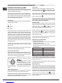
Adapting to different types of gas
To adapt the hob to a different type of gas other than default type (indicated
on the rating plate at the base of the hob or on the packaging), the burner
nozzles should be replaced as follows:
1. Remove the hob grids and slide the burners off their seats.
2. Unscrew the nozzles using a 7 mm socket spanner, and replace them
with nozzles for the new type of gas (see table 1 “Burner and nozzle
characteristics”).
3. Reassemble the parts following the above procedure in the reverse order.
4. Once this procedure is nished, replace the old rating sticker with one
indicating the new type of gas used. Sticker are available from any of our
Service Centres.

GB
11
Replacing the nozzles on separate “double ame “ burners
1. Remove the grids and slide the burners from their housings. The burner
consists of 2 separate parts (see gure);
2. Unscrew the burers with a 7 mm wrench spanner. The internal burner
has a nozzle, the external burner has two (of the same size). Replace
the nozzle with models suited to the new type of gas (see table 1).
3. Replace all the components by repeating the steps in reverse order.
• Adjusting the burners’ primary air
Does not require adjusting.
• Setting the burners to minimum
1. Turn the tap to the low ame position;
2. Remove the knob and adjust the adjustment screw, which is positioned
in or next to the tap pin, until the ame is small but steady.
! In the event of single-control DRDA (DCDR) burners, adjustment can be
performed by intervening on the 2 screws located near the tap pin (see picture).
Inner DRDA (DCDR)
burner adjustment
Total DRDA
(DCDR) burner
adjustment
3. Having adjusted the ame to the required low setting, while the burner is
alight, quickly change the position of the knob from minimum to maximum
and vice versa several times, checking that the ame does not go out.
4. Some appliances have a safety device (thermocouple) tted. If the device
fails to work when the burners are set to the low ame setting, increase
this low ame setting using the adjusting screw.
5. Once the adjustment has been made, replace the seals on the by-passes
using sealing wax or a similar substance.
6. In the event of discrete-adjustment knobs with LED visualisation, turn the
knob to the minimum power setting them remove it and intervene on the
adjustment screw located near the tap pin.
7. Minimum setting adjustment of the DRDA (DCDR) burner with discrete
adjustment and LED visualisation:
• To adjust the outer ring, turn the knob anti-clockwise to the minimum
power position.
• To adjust the minimum power setting of the inner ring, turn the knob
clockwise to the minimum power position.
• Remove the knob and intervene on the adjustment screw located near
the tap pin.
! If the appliance is connected to liquid gas, the regulation screw must be
fastened as tightly as possible.
! Once this procedure is nished, replace the old rating sticker with one
indicating the new type of gas used. Stickers are available from any of our
Service Centres.
! Should the gas pressure used be different (or vary slightly) from the
recommended pressure, a suitable pressure regulator must be tted to the
inlet pipe (in order to comply with current national regulations).
Electrical
connections
DATA PLATE
EU Regulation no. 66/2014 implementing
Directive 2009/125/EC.
standard EN 60350-2
standard EN 30-2-1
ECODESIGN
see data plate
This appliance conforms to the following
European Economic Community directives:
- 2006/95/EC dated 12/12/06 (Low Voltage)
and subsequent amendments
- 2004/108/EC dated 15/12/04
(Electromagnetic Compatibility) and
subsequent amendments
- 93/68/EEC dated 22/07/93 and subsequent
amendments.
- 2009/142/EC dated 30/11/06 (Gas) and
subsequent amendments
- 2012/19/EU and subsequent amendments.

12
GB
PK741RQO...
DC
S
A
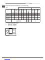
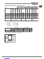
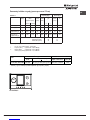
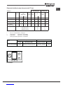
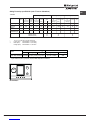
Table 1 Liquid Gas Natural Gas
Burner Diameter Thermal Thermal By-pass Nozzle Flow* Thermal Nozzle Flow*
power power 1/100 1/100 (g/h) power 1/100 (l/h)
kW kW kW
(p.c.s.*) (p.c.s.*) (p.c.s.*)
(mm) Reduced Nominal (mm) (mm) *** ** Nominal (mm)
Supply pressures Nominal (mbar)
Minimum (mbar)
Maximum (mbar)
28-30
20
35
37
25
45
20
17
25
Semi Rapid (S)
Auxiliary (A)
75
55
36
130
Double flame
(DCDR internal) (2)
Burner and nozzle specifications (for 75 cm versions only)
(2) For dual-control DRDA (DCDR) burner only
* At 15°C and 1013,25 mbar - dry gas
** Propane P. C.S. = 50.37 MJ/Kg
*** Butane P. C.S. = 49.47 MJ/Kg
Natural P. C.S. = 37.78 MJ/m³
Double flame
(DCDR external)
2 nozzles (2)
0.40
0.40
0.40
1.50
1.65
1.00
0.90
4.10
28
28
28
61
64
50
44
70x2
120
73
65
298
118
71
64
293
1.65
1.00
0.90
4.10
96(Z)
79(6)
74
110x2

GB
13
Start-up and use
! The position of the corresponding gas burner or electric hotplate* is shown
on every knob.
Gas cooker hobs are equipped with discrete power adjustment that allows
for accurately adjusting the ame to 5 different power levels. Thanks to this
system, gas hobs are also capable of guaranteeing the same cooking results
for each recipe, as the optimal power level for the desired type of cooking can
be identied in an easier, more accurate way.
Gas burners
Each burner can be adjusted to one of the following settings using the
corresponding control knob:
● Off
Maximum
Minimum
To light one of the burners, hold a lit match or lighter near the burner and, at
the same time, press down and turn the corresponding knob anti-clockwise
to the maximum setting.
Since the burner is tted with a safety device, the knob should be pressed
for approximately 2-3 seconds to allow the automatic device keeping the
ame alight to heat up.
When using models with an ignition button, light the desired burner pressing
down the corresponding knob as far as possible and turning it anticlockwise
towards the maximum setting.
! If a ame is accidentally extinguished, turn off the control knob and wait for
at least 1 minute before trying to relight it.
To switch off the burner, turn the knob in a clockwise direction until it stops
(when reaches the “●” position).
Discrete ame adjustment
The selected burner can be adjusted - by means of the knob - to 5 different
power levels. To shift between levels, simply turn the knob towards the
desired power level.
A click signals the passage from one power level to the other.
The selected power level is indicated by the
corresponding symbol (symbols )
and, on hobs equipped with a display, by the
LEDs that turn on (5 = max. power; 1 = min.
power). The system guarantees accurate ame
adjustment and uniform cooking results by
facilitating selection of the desired power level.
The “double-ame” burner
This gas burner consists of two concentric ame rings that can operate jointly
or independently (in case of dual-control only).
As the burner is tted with a safety device, the knob should be pressed
down for approximately 2-3 seconds until the device keeping the ame
automatically alight heats up.
Dual control:
Each ring comprising the burner has its own control knob:
The knob marked with the symbol controls the outer ring.
The knob marked with the symbol controls the inner ring.
To activate any one of the two rings, press the corresponding knob and turn
it anti-clockwise to the maximum power setting .
In order to use the double-ame burner to its full potential, avoid
simultaneously setting the inner ring to minimum power and the outer
ring to maximum power.
Single control:
The rings comprising the burner are activated through a single control knob.
To simultaneously turn on both rings, position the knob on the symbol
(max) - (min) then press and turn the knob anti-clockwise.
To turn on the inner ring only, position the knob on the symbol (max
) - (min) then press and turn the knob clockwise.
(to switch modes, it is necessary to switch off the burner).
To switch off the burner, press and turn the knob clockwise until it stops (when
it reaches the “●” position).
Practical advice on using the burners
To ensure the burners operate efciently:
• Use appropriate cookware for each burner (see table) so that the ames
do not extend beyond the bottom of the cookware.
• Always use cookware with a at base and a cover.
• When the contents of the pan reach boiling point, turn the knob to minimum.
Semi-Rapid (S)
Auxiliary (A)
Double Flame (DCDR internal)
Double Flame (DCDR external)
Ø Cookware Diameter (cm)
16 - 20
10 - 14
10 - 14
26 - 28
Burner
Pans to be used on 75 cm hobs
! On the models supplied with a reducer shelf, remember that this should be
used only for the Double ame internal (DCDR internal) burner when you use
casserole dishes with a diameter under 12 cm.
To identify the type of burner, refer to the designs in the section entitled, “Burner
and Nozzle Specications”.
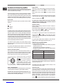
Ceramic Glass Module*
This cooktop is tted with dual-ring radiant heating elements located beneath the
glass. It is possible to turn on only the circular part of the elemement (identied by
the letter “A”) or the cooking surface can be enlarged by turning on both “A” and
“B”. To turn only the circular “A” element, simply turn the knob in the clockwise
direction to any one of the 12 available settings. To add the “B” section, turn
the knob to setting 12 and then click it into the setting. Then proceed by
turning the knob in the counter-clockwise direction to one of the 12 settings.
The gure shows the heating zones, which become red when the element is
turned on.
A. Circular heating zone;
B. Extended heating zone;
C. Indicator light to show when the cooking zone is
above 60°C, even after the heating element has
been turned off.
When the knob is on any of the settings other than “Off”, the Indicator Light
for Ceramic Glass Module comes on.
A
C
B

14
GB
Practical Advise on Using the Ceramic Glass Module
Set.
0
1
2
3
4
5
6
7
8
9
10
11
12
Radiant Burner
Off.
To melt butter and chocolate.
To heat liquids.
For creams and sauces.
For cooking at the boiling point.
For Roasts.
For boiling large pieces of meat.
For frying.
For utilising both cooking areas.
To obtain the best results from your hob:
• Use at-bottomed pans to ensure that they adhere to the cooking zone
perfectly.
• Always use pans with a diameter that is large enough to cover the hotplate
fully, in order to use all the available heat.
• Make sure that the bottom of the cookware is always dry and clean to
guarantee correct adherence and long life, not only for the cooking zones
but also for the cookware itself.
• Avoid using the same cookware that is used on gas burners: the heat
concentration on gas burners may deform the base of the pan, causing it
not to adhere correctly.
• Never leave a cooking zone on without cookware on it because as it
heats up and rapidly reaches the maximum level, which could damage
the heating elements.
! There might be traces of grease left by the glue used to seal the glass
which should be removed before using the appliance with a mild cleaning
product. During the rst few hours of use you might smell rubber but this will
disappear quickly.
Precautions and tips
! This appliance has been designed and manufactured in compliance with
international safety standards. The following warnings are provided for safety
reasons and must be read carefully.
General safety
• This is a class 3 built-in appliance.
• Gas appliances require regular air exchange to maintain efcient
operation. When installing the hob, follow the instructions provided
in the paragraph on “Positioning” the appliance.
• These instructions are only valid for the countries whose symbols
appear in the manual and on the serial number plate.
• The appliance was designed for domestic use inside the home and is
not intended for commercial or industrial use.
• The appliance must not be installed outdoors, even in covered areas. It is
extremely dangerous to leave the appliance exposed to rain and storms.
• Do not touch the appliance with bare feet or with wet or damp hands and
feet.
• The appliance must be used by adults only for the preparation of food,
in accordance with the instructions outlined in this booklet. Any other
use of the appliance (e.g. for heating the room) constitutes improper
use and is dangerous. The manufacturer may not be held liable for
any damage resulting from improper, incorrect and unreasonable
use of the appliance.
• Ensure that the power supply cables of other electrical appliances do not
come into contact with the hot parts of the oven.
• The openings used for ventilation and dispersion of heat must never be
covered.
• Always make sure the knobs are in the “●”/“○” position when the appliance
is not in use.
• When unplugging the appliance always pull the plug from the mains socket,
do not pull on the cable.
• Never carry out any cleaning or maintenance work without having detached
the plug from the mains.
• In case of malfunction, under no circumstances should you attempt to repair
the appliance yourself. Repairs carried out by inexperienced persons may
cause injury or further malfunctioning of the appliance. Contact a Service
Centre (see Assistance).
• Always make sure that pan handles are turned towards the centre of the
hob in order to avoid accidental burns.
• Do not close the glass cover (if present) when the gas burners or electric
hotplates are still hot.
• Do not leave the electric hotplate switched on without a pan placed on it.
• Do not use unstable or deformed pans.
• The appliance should not be operated by people (including children)
with reduced physical, sensory or mental capacities, by inexperienced
individuals or by anyone who is not familiar with the product. These
individuals should, at the very least, be supervised by someone who
assumes responsibility for their safety or receive preliminary instructions
relating to the operation of the appliance.
• Do not let children play with the appliance.
• The appliance is not intended to be operated by means of an external
timer or separate remote-control system.
Disposal
• When disposing of packaging material: observe local legislation so that
the packaging may be reused.
• The European Directive 2012/19/EU on Waste Electrical and
Electronic Equipment (WEEE), requires that old household electrical
appliances must not be disposed of in the normal unsorted municipal
waste stream. Old appliances must be collected separately in order
to optimise the recovery and recycling of the materials they contain
and reduce the impact on human health and the environment.
The crossed out “wheeled bin” symbol on the product reminds you of your
obligation, that when you dispose of the appliance it must be separately
collected.
Consumers should contact their local authority or retailer for information
concerning the correct disposal of their old appliance.
Respecting and conserving the environment
• Make the most of your hot plate’s residual heat by switching off cast iron hot
plates 10 minutes before the end of your cooking time and glass ceramic
hot plates 5 minutes before the end of cooking time.

GB
15
• The base of your pot or pan should cover the hot plate. If it is smaller,
precious energy will be wasted and pots that boil over leave encrusted
remains that can be difcult to remove.
• Cook your food in closed pots or pans with well-tting lids and use as little
water as possible. Cooking with the lid off will greatly increase energy
consumption.
• Use purely at pots and pans.
• If you are cooking something that takes a long time, it’s worth using a
pressure cooker, which is twice as fast and saves a third of the energy.
Maintenance and care
Switching the appliance off
Disconnect your appliance from the electricity supply before carrying out
any work on it.
Cleaning the appliance
! Do not use abrasive or corrosive detergents such as stain removers, anti-rust
products, powder detergents or sponges with abrasive surfaces: these may
scratch the surface beyond repair.
! Never use steam cleaners or pressure cleaners on the appliance.
• It is usually enough to wash the hob with a damp sponge and dry it with
absorbent kitchen roll.
• The removable parts of the burners should be washed frequently with
warm water and soap and any burnt-on substances removed.
• For hobs which ligth automatically, the terminal part of the electronic instant
lighting devices should be cleaned frequently and the gas outlet holes
should be checked for blockages.
• Before using the ceramic glass module, the surface must be cleaned,
using a damp cloth to remove dust or food residues. The ceramic glass
surface should be cleaned regularly with a soultion of warm water and a
non-abrasive detergent.
• Stainless steel can be marked by hard water that has been left on the
surface for a long time, or by aggressive detergents containing phosphorus.
After cleaning, rinse and dry any remaining drops of water.
Periodically, special products will need to
be used to clean the surface. First, remove
all food buildup or grease with a cleaning
scraper, e.g. (not supplied).
Clean the cooking surface when it is still
warm with a suitable cleaning product
(such as the one in the Solutions product
line available from any After-Sales Service
Centre) and paper towels. Then rub with a damp cloth and dry. Aluminum
foil, plastic items, objects made of synthetic material, sugar or foods with
a high sugar content that have melted onto the surface must be removed
immediatley with a scraper while the cooking surface is still hot.
Special cleaning products for ceramic glass
surfaces form a transparent protective
layer which ghts diry buildup. This also
protects the surface from damage caused
by food with a high sugar content. Do not
use abrasive sponges or cleaning products
under any circumstances. This holds true
for chemically aggressive cleaners, like
oven sprays and stain removers.
! It is not necessary to remove the pan supports in order to clean the hob
surface. Thanks to the support system, simply lift and hold the pan supports
or rotate them until they rest against a rear support.
Do not place the hot grids on top of the glass cover (if applicable),
otherwise the rubber plugs on the glass may be damaged.
Gas tap maintenance
Over time, the taps may become jammed or difcult to turn. If this happens,
the tap must be replaced.
! This procedure must be performed by a qualied technician authorised
by the manufacturer.
Troubleshooting
It may happen that the appliance does not function properly or at all. Before
calling the service centre for assistance, check if anything can be done. First,
check to see that there are no interruptions in the gas and electrical supplies,
and, in particular, that the gas valves for the mains are open.
The burner does not light or the ame is not even around the burner.
Check whether:
• The gas holes on the burner are clogged.
• All the movable parts that make up the burner are mounted correctly.
• There are draughts near the appliance.
The ame dies in models with a safety device.
Check to make sure that:
• You pressed the knob all the way in.
• You keep the knob pressed in long enough to activate the safety device.
• The gas holes are not blocked in the area corresponding to the safety
device.
The burner does not remain lit when set to minimum.
Check to make sure that:
• The gas holes are not blocked.
• There are no draughts near the appliance.
• The minimum setting has been adjusted properly.
The cookware is unstable.
Check to make sure that:
• The bottom of the cookware is perfectly at.
• The cookware is positioned correctly at the centre of the burner.
• The pan support grids have been positioned correctly.

16
PL
Instalacja
! Ważnym jest, aby zachować niniejszą instrukcję dla przyszłych konsultacji.
W razie sprzedaży, odsprzedania, czy przeniesienia, należy upewnić się,
czy znajduje się ona wraz z urządzeniem i odpowiednimi uwagami, aby
poinformować nowego właściciela o jego funkcjonowaniu.
! Należy uważnie przeczytać instrukcję: zawieraja ona ważne informacje
dotyczące instalacji, użytkowania i bezpieczeństwa.
Ustawienie
! Opakowania nie są zabawkami dla dzieci i należy je usunąć zgodnie z
normami zbierania odpadów (patrz Środki ostrożności i zalecenia).
! Instalacja powinna zostać wykonana zgodnie z niniejszymi instrukcjami i
przez personel zawodowo do tego przygotowany. Błędna instalacja może
spowodować powstanie szkód wobec osób, zwierząt lub rzeczy.
! Niniejsze urządzenie może zostać zainstalowane wyłącznie w
pomieszczeniach ze stałą wentylacją, zgodnie z zaleceniami obowiązujących
norm krajowych. Należy dochować następujących warunków:
• Pomieszczenie powinno posiadać system odprowadzający na zewnątrz
gazów spalinowych składający się z okapu lub wyciągu elektrycznego,
uruchamianego automatycznie każdorazowo podczas uruchomienia
urządzenia.
W kominie lub w odgałęzionym przewodzie dymnym
(przeznaczonym dla urządzeń kuchennych)
Bezpośrednio
na zewnątrz
• Pomieszczenie powinno posiadać funkcjonalny system dopływu
powietrza umożliwiający normalne spalanie. Dopływ niezbędnego do
spalania powietrza nie powinien być mniejszy niż 2 m3/h na każdy kW
zainstalowanej mocy.
System może polegać na bezpośrednim
poborze powietrza z zewnątrz budynku przy
pomocy kanału o przekroju użytecznym
przynajmniej 100 cm2 i zabezpieczonego przed
przypadkowym zaślepieniem.
Albo też, w sposób pośredni, z przyległych
pomieszczeń wyposażonych w przewód
wentylacyjny jak opisany powyżej, a nie będący
częścią wspólną dla całej nieruchomości
ani nie mający połączeń z pomieszczeniami
sypialni lub w których występuje zagrożenie
pożarem.
• Intensywne i długotrwałe stosowanie urządzenia może wymagać
dodatkowej wentylacji, na przykład otwarcia okna lub bardziej skutecznej
wentylacji, zwiększającej mechaniczną siłę ssania (jeśli już istnieje).
• Skroplone gazy pochodne ropy naftowej, cięższe od powietrza, opadają
w dół. Dlatego pomieszczenia, w których przechowywane są butle GPL
powinny przewidywać otwory prowadzące na zewnątrz umożliwiające
spływanie ku dołowi ewentualnych wycieków gazu. Ponadto butle
A
Przykłady otwarcia
wentylacji
dla powietrza do spalania
Pomieszczenie
przyległe
Pomieszczenie
przeznaczone
do przewietrzania
Zwiększenie szczeliny pomiędzy
drzwiami a podłogą
GPL, niezaleznże od tego czy są puste, czy częściowo napełnione,
nie powinny być instalowane ani składowane w pomieszczeniach lub
komorach o położonych poniżej poziomu podłogi (piwnice, itp.). Dobrze
jest przechowywać w pomieszczeniu jedynie butle aktualnie użytkowaną,
umocowaną w sposób nie narażający jej na bezpośrednie oddziaływanie
źródeł ciepła (piece, kominki, piecyki, itp.) mogące doprowadzić do wzrostu
temperatury powietrza powyżej 50°C.
Zabudowa
W celu poprawnego zainstalowania płyty grzewczej należy zachować
następujące środki ostrożności:
• Meble znajdujące się obok, a których wysokość przekracza wysokość
płyty roboczej, powinny zostać odsunięte przynajmniej na 200 mm od
krawędzi płyty roboczej.
• Okapy powinny być zainstalowane zgodnie z warunkami wymaganymi
podanymi przez instrukcje samych okapów, jednak w minimalnej odległości
650 mm (patrz ilustracja).
• Umieścić sąsiadujące z okapem szafki wiszące na wysokości minimalne
od szczytu 420 mm (patrz ilustracja).
By płyta grzewcza mogła być zainstalowana
pod szafką wiszącą, ta ostatnia powinna
znajdować się w odległości minimalnej od
szczytu wynoszącej 700 mm.
• Wnęka na obudowę powinna mieć wymiary podane na ilustracji.
Przewidziano uchwyty mocujące umożliwiające zamocowanie płyty na
podstawie posiadającej grubość od 20 do 40 mm. Aby solidnie zamocować
płytę zaleca się zastosowanie wszystkich uchwytów znajdujących się do
dyspozycji.
555 mm
55 mm
475 mm
Przed zainstalowaniem płyty kuchennej, należy zdjąć ruszty i palniki i odwrócić
ją częścią spodnią do góry, uważając na to, aby nie uszkodzić termopar i
świec zapłonowych.
Następnie należy założyć uszczelki
dostarczone na wyposażeniu na
zewnętrzne krawędzie płyty kuchennej,
aby uniemożliwić przedostawanie się
powietrza, wilgoci i wody (zob. rysunek).
Aby wykonać powyższą czynność
prawidłowo, należy upewnić się, że
uszczelniane powierzchnie są czyste, suche i nie są zabrudzone smarami/
olejami.
Schemat mocowania uchwytów
Położenie uchwytu w Położenie uchwytu w
stosunku do blatu H=20mm stosunku do blatu H=30mm
600mm min.
420mm min.
650mm min.

17
PL
Przód
Położenie uchwytu w Tył
stosunku do blatu H=40mm
! Stosować uchwyty zawarte w „zestawie akcesoriów”
• W przypadku, gdy płyta nie jest zainstalowana na zabudowanym
piekarniku, koniecznym jest zastosowanie płyty drewnianej jako izolatora.
Powinna być ona zamocowana w odległości minimum 20 mm od dolnej
części samej płyty roboczej.
Obieg powietrza
W celu zapewnienia dobrego obiegu powietrza koniecznym jest usunięcie
tylnej ścianki komory. Najlepiej zainstalować piekarnik w taki sposób, aby
wspierał się na dwóch listwach drewnianych lub na drewnianej desce z
prześwitem przynajmniej 45 x 560 mm (patrz ilustracje).
560 mm.
45 mm.
W przypadku instalacji na piekarniku nie wyposażonym w obieg chłodzący
należy zapewnić swobodny przepływ powietrza w celu właściwej wentylacji.
Podłączenie do sieci elektrycznej
Płyty wyposażone w przewód zasilający trójżyłowy dostosowane są do
pracy na prąd zmienny przy napięciu i częstotliwości zasilania wskazanych
na tabliczce znamionowej (umieszczonej w dolnej części płyty). Przewód
uziemienia w sznurze oznaczony jest kolorem żółto-zielonym. W
przypadku zainstalowania ponad piekarnikiem zabudowanym podłączenia
elektryczne płyty i piekarnika powinny być wykonane osobno, tak z przyczyn
bezpieczeństwa elektrycznego, jak i dla ułatwienia ewentualnego wyjęcia
piekarnika.
Podłączenie przewodu zasilającego do sieci
Zamocować na przewodzie znormalizowaną wtyczkę do obciążeń
wskazanych na tabliczce znamionowej.
W przypadku bezpośredniego podłączenia do sieci koniecznym jest
zainstalowanie pomiędzy urządzeniem a siecią wyłącznika polowego z
otwarciem minimalnym pomiędzy stykami 3 mm przeznaczonego do obciążeń
i odpowiadającego obowiązującym normom (przewód uziemienia nie
powinien być przerywany przez wyłącznik). Przewód zasilania powinien być
umieszczony w taki sposób, aby w żadnym punkcie temperatura otoczenia
nie przekraczała 50°C.
! Instalator odpowiada za poprawność podłączenia elektrycznego i za
zachowanie norm bezpieczeństwa.
Przed wykonaniem podłączenia należy upewnić się, czy:
• gniazdko posiada odpowiednie uziemienie i zgodne jest z obowiązującymi
przepisami;
• gniazdko jest w stanie wytrzymać obciążenie maksymalnej mocy
urządzenia wskazane na tabliczce znamionowej;
• napięcie zasilania odpowiada wartościom podanym na tabliczce
znamionowej;
• gniazdko musi być odpowiednie dla wtyczki urządzenia. W przeciwnym
razie należy wymienić gniazdko lub wtyczkę; nie stosować przedłużaczy,
ani rozgałęźników.
! Po zainstalowaniu urządzenia przewód elektryczny i gniazdko powinny być
łatwo dostępne.
! Kabla nie wolno zginać ani przyciskać.
! Przewód elektryczny musi być okresowo sprawdzany i wymieniany jedynie
przez autoryzowanych techników (patrz Serwis).
! Producent odrzuca wszelką odpowiedzialność w przypadku, gdy niniejsze
zasady nie będą przestrzegane.
Podłączenie gazu
Podłączenie urządzenia do przewodów lub butli gazowej powinno zostać
wykonane zgodnie z zaleceniami obowiązujących norm krajowych dopiero po
upewnieniu się, że jest ono wyregulowane do pracy z rodzajem gazu, którym
będzie zasilane. W przeciwnym wypadku wykonać czynności wskazane w
paragrae “Dostosowanie do różnych rodzajów gazu” W przypadku zasilania
płynnym gazem z butli, stosować regulatory ciśnienia zgodne z obowiązującymi
normami krajowymi.
! W celu uzyskania pewności pracy, odpowiedniego zużycia energii i
zwiększenia trwałości urządzenia należy upewnić się czy ciśnienie zasilania
mieści się w granicach zalecanych w tabeli 1 „Charakterystyki palników i
dysz”.
Podłączenie przewodem sztywnym (miedź lub stal)
! Podłączenie do urządzenia gazowego powinno być wykonane w taki sposób,
aby nie powodować żądnych naprężeń urządzenia.
Na przewodzie zasilającym urządzenie znajduje się ruchome złącze
kolankowe “L” , którego szczelność zapewniona jest uszczelką. W przypadku
gdyby okazało się, że koniecznym jest obrócenie kolanka należy obowiązkowo
wymienić uszczelkę (na wyposażeniu urządzenia). Złącze wejściowe gazu
do urządzenia jest gwintowane gwintem gazowym 1/2 walcowym męskim.
Podłączenie z przewodem elastycznym ze stali nierdzewnej o pełnych
ściankach z gwintowanymi złączami.
Złącze wejściowe gazu do urządzenia jest gwintowane gwintem gazowym
1/2 walcowym męskim.
Użycie przewodów tego rodzaju powinno być wykonane w ten sposób, aby
ich długość, w warunkach maksymalnego rozszerzenia nie przekraczała
2000 mm. Po wykonaniu podłaczenia upewnic się, czy metalowy przewód
elastyczny nie styka się z elementami ruchomymi, ani nie jest przygnieciony.
! Stosować wyłącznie przewody i uszczelki zgodne z obowiązującymi normami
krajowymi.

18
PL
Kontrola szczelności
! Po zakończeniu instalacji skontrolować szczelność wszystkich złącz stosując
w tym celu wodny rozwór mydła, nigdy płomień.
Dostosowanie do różnych rodzajów gazu
W celu dostosowania płyty do innego rodzaju gazu niż ten, do którego
jest przystosowana (wskazanego na etykiecie w dolnej części płyty lub
na opakowaniu), należy wymienić dysze palników wykonując następujące
czynności:
1. Zdjąć ruszt z płyty i wykręcić palniki z ich gniazd.
2. Odkręcić dysze posługując się kluczem rurowym 7mm i wymienić je na
nowy rodzaj przystosowany do nowego rodzaju gazu (patrz tabela 1
„Charakterystyki palników i dysz”).
3. Ponownie zmontować części w kolejności odwrotnej.
4. Na zakończenie czynności wymienić poprzednią etykietę regulacyjna
na nową, odpowiadająca nowemu rodzajowi gazu, dostepną w naszych
centrach obsługi technicznej.
Wymiana dysz palnika Podwójna Korona
1. Zdjąć ruszt z płyty i wykręcić palniki z ich gniazd.Palnik składa się z dwóch
osobnych części (patrz ilustracja).
2. Odkręcić dysze posługując się kluczem rurowym 7mm. Palnik wewnętrzny
ma jedną dyszę. Palnik zewnętrzny ma dwie dysze o tej samej średnicy.
Wymienić dysze na te przystosowane do nowego rodzaju gazu (patrz
tabela 1).
3. Ponownie zmontować części w odwrotnej kolejności.
• Regulacja powietrza pierwotnego palników
Palniki nie wymagają żadnej regulacji powietrza pierwotnego.
• Regulacja minimów
1. Ustawić kurek w położeniu minimum;
2. Zdjąć pokrętło i posługując się śrubą regulacyjną znajdującą się wewnątrz
lub obok osi kurka uzyskać najmniejszy regularny płomień.
! W przypadku palnika DCDR o pojedyńczej kontroli, regulacja może być
wykonywana przez interwencję na 2 śruby znajdujące się obok osi kurka
(patrz ilustracja).
Regolazione
DCDR interno
Regolazione
DCDR totale
3. Upewnić się, czy podczas szybkiego obracania pokrętłem z położenia
maksymalnego do minimalnego nie występuje gaśnięcie palników.
4. W urządzeniach wyposażonych w urządzenie zabezpieczające
(termopara) w przypadku niezadziałania urządzenia z palnikami
ustawionymi na minimum należy zwiększyć minimalne przepływy przy
pomocy śruby regulacyjnej.
5. Po zakończeniu regulacji ponownie założyć plomby lakowe, lub z
równorzędnego materiału, umieszczone na obejściu.
6. W przypadku pokręteł o dyskretnej regulacji z wizualizacją LED, obrócić
pokrętło do położenia minimalnej mocy, następnie je wyjąć i wyregulować
płomień za pomocą śruby regulacyjnej znajdującej się obok osi kurka.
7. Regulacja minimów dla palnika DCDR z dyskretną regulacją i wizualizacją
LED:
• Aby wyregulować palnik, obrócić pokrętło w kierunku przeciwnym
do ruchu wskazowek zegara, do położenia minimalnej mocy. Zdjąć
pokrętło i wyregulować płomień za pomocą śruby regulacyjnej
znajdującej się obok osi kurka.
• Aby wyregulować minimalną moc wewnętrzej korony palnika, obrócić
pokrętło w kierunku zgodnym z ruchem wskazowek zegara, do
położenia minimalnej mocy. Zdjąć pokrętło i wyregulować płomień za
pomocą śruby regulacyjnej znajdującej się obok osi kurka.
! W przypadku gazu płynnego śruba regulacyjna powinna być dokręcona
do końca.
! Po zakończeniu operacji należy wymienić poprzednia etykietę nastawień na
etykietę odpowiadającą nowemu gazowi użytkowemu, dostępną w naszych
centrach obsługi technicznej.
! W sytuacji, gdy ciśnienie stosowanego gazu stanie się różne (lub zmienne)
od przewidywanego, koniecznym jest zainstalowanie na przewodach
doprowadzających regulatora ciśnienia (zgodnie z obowiązującą normą
krajową).
Podłączenia
elektryczne
TABLICZKA ZNAMIONOWA
patrz tabliczka znamionowa
Niniejsze urządzenie zostało wyprodukowane
zgodnie z następującymi dyrektywami unijnymi:
- 2006/95/WE z 12/12/06 (o Niskim Napięciu)
wraz z późniejszymi zmianami
- 2004/108/WE z 15/12/04 (o Zgodności
Elektromagnetycznej) wraz z późniejszymi
zmianami
- 93/68/EWG z 22/07/93 wraz z późniejszymi
zmianami
- 2009/142/WE z 30/11/09 (Gaz) wraz z
późniejszymi zmianami
- 2012/19/UE wraz z późniejszymi zmianami
Rozporządzenie UE nr 66/2014,
integrujące dyrektywę 2009/125/KE
Rozporządzenie EN 60350-2
Rozporządzenie EN 30-2-1
ECODESIGN

19
PL
Nominalne (mbar)
Minimalne (mbar)
Maksymalne (mbar)
20
17
25
37
25
44
Ciśnienia zasilania
Palnik
Ś
rednica
(mm) Moc
cieplna
kW
(p.c.s.*)
75
55
36
130
0.45
0.45
0.45
1.65
Zreduk.
By-pass
1/100
(mm)
28
28
28
61
Przepływ
*
g/godz.
***
Dysza
1/100
Przepływ
*
l/godz.
(mm)
96(Z)
79(6)
74
107x2
167
100
86
371
131
76
69
298
**
129
75
68
293
Charakterystyki palników oraz dysz (tylko dla wersji 75 cm.)
(2) Tylko dla palnika DCDR o podwójnej kontroli
* W 15°C i 1013,25 mbar - gaz suchy
** Propan (G31) P.C.S. = 50.37 MJ/Kg
*** Butan (G30) P.C.S. = 49.47 MJ/Kg
Naturalny (G20) P.C.S. = 37.78 MJ/m
Naturalny (G2.350) P.C.S. = 27.20 MJ/m
Gaz
płynny
Gaz
naturalny
(G20)
Gaz
naturalny
(G2.350)
Tabela 1
Moc
cieplna
kW
(p.c.s.*)
1.75
1.05
0.90
3.90
Moc
cieplna
kW
(p.c.s.*)
Nomin.
1.80
1.05
0.95
4.10
Dysza
1/100
(mm)
64
50
44
70x2
Nomin.
Moc
cieplna
kW
(p.c.s.*)
Nomin.
Dysza
1/100
(mm)
Przepływ
*
l/godz.
1.75
1.05
0.90
3.90
135
106(6)
102
165x2
231
139
119
516
13
10
16
3
3
P
ół
szybki (
Ś
redni) (S)
Pomocniczy (Ma
ł
y) (A)
7,90 (574 g/h-G30) (564 g/h-G31)
PK 741 RQO GH/HA EE
Podwójna Korona
(DCDR
wewnętrzny)
(2)
Podwójna Korona
(DCDR
zewnętrzny)
(2)
II2ELs3B/P
Część gazowa
Moc nominalna (kW)Klasa
Model Część elektryczna
220-240V~ 50/60Hz
Napięcie i częstotliwość
(1) Moc (W)
2000
Wartości w g/h odnoszą się do p
rzepływu
gazu ciekłego (butan, propan).
(1)
PK741RQO...
DC
S
A

20
PL
Uruchomienie i użytkowanie
! Dla każdego z pokręteł wskazane jest położenie palnika gazowego lub płyty
elektrycznej* odpowiadających im.
Płyta gazowa wyposażona jest w dyskretną regulację mocy, która umożliwia
precyzyjną regulację płomienia na 5 różnych poziomach mocy. Dzięki temu
systemowi, możliwe jest zagwarantowanie tych samych wyników gotowania
dla każdej receptury, jako że, identykacja optymalnego poziomu mocy dla
wybranego sposobu gotowania jest prostsza i bardziej dokładna.
Palniki gazowe
Wybrany palnik może być regulowany odpowiednim pokrętłem w następujący
sposób:
● Wyłączony
Maksimum
Minimum
W celu włączenia któregoś z palników, należy zbliżyć do niego płomień lub
zapalarkę, nacisnąć do końca odpowiadające mu pokrętło i obrócić je w
kierunku przeciwnym do wskazówek zegara aż ustawi się na maksymalną
moc.
W modelach wyposażonych w urządzenia zabezpieczające, należy
przytrzymać wduszone pokrętło przez około 2-3 sekundy aż rozgrzeje się
urządzenie automatycznie podtrzymujące zapalony płomień.
W modelach wyposażonych w urządzenie zapłonowe wewnątrz pokrętła, aby
włączyć wybrany palnik, wystarczy nacisnąć do końca odpowiadające mu
pokrętło i obrócić je w kierunku przeciwnym do wskazówek zegara aż ustawi
się na maksymalną moc, przytrzymując je wciśnięte dopóki nie nastąpi zapłon.
! W przypadku przypadkowego zgaśnięcia płomienia palnika, zakręcić pokrętło
sterujące i ponowić próbę zapalenia po upływie przynajmniej 1 minuty.
Aby zgasić palnik należy obrócić pokrętło zgodnie z ruchem wskazówek
zegara aż do zatrzymania (odpowiadającego symbolowi “●”).
Dyskretna regulacja płomienia
Wybrany palnik można regulować za pomocą pokrętła na 5 różnych
poziomach mocy.
Aby przejść z jednego poziomu na drugi wystarczy obrócić pokrętło w kierunku
wybranego poziomu.
Kliknięcie sygnalizuje przejście z jednego poziomu mocy na inny.
Wybrany poziom mocy oznaczony jest przez
odpowiednie symbole (symbole
), a w przypadku płyt wyposażonych w
wyświetlacz, porzez zapalenie się diod (5 =
maksymalna moc, 1 = minimalna moc).
System gwarantuje dokładną regulację
płomienia i jednolite rezultaty gotowania,
ułatwiając wybór żądanego poziomu mocy.
Palnik “podwójny plomień”
Palnik ten, składa się z dwóch koncentrycznych koron, które mogą
funkcjonować razem lub osobno (tylko w przypadku podwójnej kontroli).
Jako że palnik wyposażony jest w urządzenie zabezpieczające, należy
przytrzymać wduszone pokrętło przez około 2-3 sekundy aż rozgrzeje się
urządzenie automatycznie podtrzymujące zapalony płomień.
Podwójna kontrola:
Każda korona, która komponuje palnik posiada własne pokrętło:
Pokrętło oznaczone symbolem kontroluje zewnętrzną koronę.
Pokrętło oznaczone symbolem kontroluje wewnętrzną koronę.
Aby włączyć jedną z dwóch koron, naciśnąć odpowiednie pokrętło i obrócić w
kierunku przeciwnym do ruchu wskazówek zegara aż do pozycji maksymalnej
mocy .
W celu wykorzystania całkowietgo potencjału palnika z podwójnym
płomieniem, unikać jednoczesnego ustawienia korny wewnętrznej na
minimalną moc i korony zewnętrznej na maksymalną mocy.
Pojedyńcza kontrola:
Korony składąjace się na palnik, aktywowane są za
pomocą jednego pokrętła.
Aby włączyć jednocześnie obie korony, naciśnąć i przekręcić pokrętło w
kierunku przeciwnym do ruchu wskazówek zegara ustawiając je na symbol
(maks) - (min).
Aby włączyć tylko wewnętrzna koronę naciśnąć i przekręcić pokrętło w
kierunku zgodnym z ruchem wskazówek zegara ustawiając je na symbol
(maks) - (min)
(aby przejść z jednego trybu na drugi, należy wyłączyć palnik).
Aby zgasić palnik należy obrócić pokrętło zgodnie z ruchem wskazówek
zegara aż do zatrzymania (odpowiadającego symbolowi “●”)
Zalecenia praktyczne użytkowania palników
W celu uzyskania maksymalnej wydajności należy pamiętać, co następuje:
• Stosować naczynia odpowiednie dla każdego z palników (patrz tabela) w
celu uniknięcia wychodzenia płomieni poza pole dna naczyń.
• Stosować zawsze naczynia o dnie płaskim i z przykrywką.
• W chwili zagotowania się obrócić pokrętło do położenia minimum.
Garnki do użycia dla płyt 75 cm
Ø
Ś
rednica naczyń (cm)
Półszybki (
Ś
redni) (S)
Pomocniczy (Mały) (A)
Podwójna Korona
(DCDR wewn
ę
trzny)
Podwójna Korona
(DCDR zewn
ę
trzny)
16 - 20
10 - 14
10 - 14
26 - 28
Palnik
! W modelach wyposażonych w ruszt redukcyjny , pamiętać, że powinien być
on używany tylko dla wewnętrznej korony palnika Podwójna Korona, kiedy
używane są garnki o śrenicy mniejszej niż 12 cm.
W celu zidentyfikowania rodzaju palnika zapoznać się z ilustracjami
znajdującymi się w paragrae „Charakterystyki palników i dysz”.
Płyta ceramiczna
Ta płyta kuchenna jest wyposażona w podwójne pole grzejne umieszczone
pod szkłem. Możliwe jest włączenie jedynie części kołowej (oznaczonej literą
“A”) lub powiększenie powierzchni grzewczej przez włączenie obydwu części
“A” i “B”. Aby włączyć tylko część kołową “A”, wystarczy obrócić pokrętło w
kierunku zgodnym z ruchem wskazówek zegara do jednej z 12 dostępnych
pozycji. Aby dodać sekcję “B”, obrócić pokrętło do pozycji 12, a następnie
przełączyć w pozycję . Następnie wybrać jedno z 12 ustawień przez
obracanie pokrętła w kierunku przeciwnym do ruchu wskazówek zegara.
Ilustracja przedstawia strefy grzewcze, które stają się czerwone, gdy element
jest włączony.
Strona się ładuje...
Strona się ładuje...
Strona się ładuje...
Strona się ładuje...
Strona się ładuje...
Strona się ładuje...
Strona się ładuje...
Strona się ładuje...
Strona się ładuje...
Strona się ładuje...
Strona się ładuje...
Strona się ładuje...
Strona się ładuje...
Strona się ładuje...
Strona się ładuje...
Strona się ładuje...
Strona się ładuje...
Strona się ładuje...
Strona się ładuje...
Strona się ładuje...
Strona się ładuje...
Strona się ładuje...
Strona się ładuje...
Strona się ładuje...
Strona się ładuje...
Strona się ładuje...
Strona się ładuje...
Strona się ładuje...
-
 1
1
-
 2
2
-
 3
3
-
 4
4
-
 5
5
-
 6
6
-
 7
7
-
 8
8
-
 9
9
-
 10
10
-
 11
11
-
 12
12
-
 13
13
-
 14
14
-
 15
15
-
 16
16
-
 17
17
-
 18
18
-
 19
19
-
 20
20
-
 21
21
-
 22
22
-
 23
23
-
 24
24
-
 25
25
-
 26
26
-
 27
27
-
 28
28
-
 29
29
-
 30
30
-
 31
31
-
 32
32
-
 33
33
-
 34
34
-
 35
35
-
 36
36
-
 37
37
-
 38
38
-
 39
39
-
 40
40
-
 41
41
-
 42
42
-
 43
43
-
 44
44
-
 45
45
-
 46
46
-
 47
47
-
 48
48


Hotpoint Ariston PK 741 RQO GH /HA EE Operating Instructions Manual
- Kategoria
- Płyty
- Typ
- Operating Instructions Manual
w innych językach
- slovenčina: Hotpoint Ariston PK 741 RQO GH /HA EE