
PK 640 R L GH /HA EE
PK 640 R GH /HA EE
PK 741 RQO GH /HA EE
PK 750 R GH /HA EE
English
Operating Instructions
HOB
Contents
Operating Instructions,1
Warnings,2
Assistance,5
Description of the appliance,6
Installation,8
Start-up and use,13
Precautions and tips,14
Maintenance and care,15
Troubleshooting,16
Українська
Інструкція по використанню
Варильна поверхня
Polski
Instrukcja obsługi
PŁYTA
Magyar
Használati útmutató
Főzőlap
Spis treści
Instrukcja obsługi,1
Ostrzezenia,3
Serwis Techniczny,5
Opis urządzenia,7
Instalacja,27
Uruchomienie i użytkowanie,32
Zalecenia i środki ostrożności,34
Konserwacja i utrzymanie,34
Anomalie i środki zaradcze,35
Зміст
Інструкція по використанню,1
Попередження,2
Допомога,5
Опис приладу,6
Встановлення,17
Підключення й використання,23
Застереження й поради,25
Технічне обслуговування й догляд,25
Пошук і усунення несправностей,26
Tartalomjegyzék
Használati útmutató,1
Figyelmeztetések,4
Szerviz,5
A készülék leírása,7
Beszerelés,36
Bekapcsolás és használat,41
Óvintézkedések és tanácsok,42
Karbantartás és ápolás,43
Hibaelhárítás,44

2
Warnings
WARNING: The appliance and its
accessible parts become hot during use.
Care should be taken to avoid touching
heating elements. Children less than 8
years of age shall be kept away unless
continuously supervised. This appliance
can be used by children aged from 8 years
and above and persons with reduced
physical, sensory or mental capabilities
or lack of experience and knowledge
if they have been given supervision
or instruction concerning use of the
appliance in a safe way and understand
the hazards involved. Children shall not
play with the appliance. Cleaning and
user maintenance shall not be made by
children without supervision.
WARNING: Unattended cooking on a hob
with fat or oil can be dangerous and may
result in re. NEVER try to extinguish a
re with water, but switch off the appliance
and then cover ame e.g. with a lid or a
re blanket.
WARNING: Danger of re: do not store
items on the cooking surfaces.
WARNING: If the surface in glass-ceramic
is cracked, switch off the appliance to
avoid the possibility of electric shock.
Never use steam cleaners or pressure
cleaners on the appliance.
Remove any liquid from the lid before
opening it. Do not close the glass cover (if
present) when the gas burners or electric
hotplates are still hot.
The appliance is not intended to be
operated by means of an external timer
or separate remote control system.
CAUTION: the use of inappropriate hob
guards can cause accidents.
CAUTION: In case of hotplate glass
breakage:
- shut immediately off all burners and any
electrical heating element and isolate the
appliance from the power supply
- do not touch the appliance surface.
Попередження
УВАГА! Прилад і його доступні частини
нагріваються під час роботи. Будьте
обережні й не торкайтеся нагрівальних
елементів. Діти до 8 років мають
знаходитися від плити на безпечній
відстані або під безперервним
наглядом з боку дорослих. Цей прилад
може використовуватися дітьми у
віці від 8 років і старше та особами з
обмеженими фізичними, сенсорними
або розумовими здібностями, або
при відсутності досвіду й знань,
тільки якщо вони перебувають під
наглядом або проінструктовані з
питань безпечного використання
приладу й розуміють ризик, якому
піддаються. Діти не повинні гратися
з приладом. Очищення та догляд за
приладом може виконуватися дітьми
лише під безперервним наглядом з
боку дорослих
УВАГА! Готування їжі на плиті без
догляду з використанням жиру або олії
може бути небезпечним і призвести
до загоряння. НІ В ЯКОМУ РАЗІ не
намагайтеся гасити пожежу водою.
Вимкніть прилад і потім накрийте
полум’я, наприклад, кришкою або
протипожежною ковдрою.
УВАГА! Небезпека пожежі: не складуйте
речі на варильній поверхні.

3
УВАГА! При появі на склокерамічній
поверхні тріщин вимкніть прилад,
щоб уникнути можливого ураження
електричним струмом.
Для очищення приладу ніколи не
користуйтеся паровими пристроями
або пристроями під тиском.
Перш ніж відкривати кришку, протріть
її насухо. Не закривайте скляну кришку
(в разі її наявності), коли газові або
електричні конфорки ще гарячі.
Прилад не призначений для
функціонування в комбінації із
зовнішнім таймером або окремою
системою дистанційного управління.
ЗАСТЕРЕЖЕННЯ: Використання
невідповідного захисту варильної
поверхні може стати причиною
нещасного випадку.
ЗАСТЕРЕЖЕННЯ: В разі поломки скла
варильної поверхні:
- негайно вимкніть всі конфорки й
електричний нагрівальний елемент, а
також відключіть прилад від джерела
живлення
- не торкайтеся поверхні приладу.
Ostrzezenia
UWAGA: To urządzenie oraz jego
dostępne części silnie się rozgrzewają
podczas użytkowania. Należy uważać,
aby nie dotknąć elementów grzejnych.
Nie pozwalać, aby dzieci poniżej 8 roku
życia zbliżały się do urządzenia, jeśli nie
są pod stałym nadzorem dorosłych.
Z niniejszego urządzenia mogą korzystać
dzieci powyżej 8 roku życia i osoby o
ograniczonych zdolnościach zycznych,
zmysłowych bądź umysłowych, jak również
osoby nieposiadające doświadczenia lub
znajomości urządzenia, jeśli znajdują się
one pod nadzorem innych osób lub jeśli
zostały pouczone na temat bezpiecznego
sposobu użycia urządzenia oraz zdają
sobie sprawę ze związanych z nim
zagrożeń. Dzieci nie powinny bawić
się urządzeniem. Prace związane z
czyszczeniem i konserwacją nie mogą
być wykonywane przez dzieci, jeśli nie
są one nadzorowane.
UWAGA: Pozostawienie bez nadzoru na
kuchence tłuszczów i olejów może być
niebezpieczne i może spowodować pożar.
Nie należy NIGDY próbować ugasić
płomieni/pożaru wodą; należy wyłączyć
urządzenie i przykryć płomień np.
pokrywką lub ognioodpornym kocem.
UWAGA: Ryzyko pożaru: nie pozostawiać
przedmiotów na powierzchniach
grzejnych.
UWAGA: Jeżeli powierzchnia ze szkła
ceramicznego jest pęknięta, należy
wyłączyć urządzenie, aby uniknąć
niebezpieczeństwa porażenia prądem
elektrycznym.
Nie stosować nigdy oczyszczaczy
parowych lub ciśnieniowych do
czyszczenia urządzenia.
Usunąć ewentualne płyny na pokrywie
przed jej otwarciem. Nie zamykać szklanej
pokrywy (jeśli jest częścią wyposażenia),
jeśli palniki gazowe lub płyta elektryczna
są jeszcze rozgrzane.
Urządzenie nie jest przeznaczone do
włączania przy użyciu zewnętrznego
przekaźnika czasowego lub zdalnego
systemu sterowania.
UWAGA: użycie niewłaściwych
zabezpieczeń płyty może być przyczyną
wypadków.

4
UWAGA: W przypadku uszkodzenia
szkła płyty:
- wyłączyć natychmiast wszystkie palniki
i ewentualne elementy grzejne i odłączyć
urządzenie od sieci elektrycznej
- nie dotykać powierzchni urządzenia.
Figyelmeztetések
FIGYELMEZTETÉS: A készülék és
a hozzáférhető részei felforrósodnak
a használat során. Ügyeljen rá, hogy
ne érjen a fűtőelemekhez. A 8 évnél
atalabb gyermekeket távol kell tartani,
ha nincsenek folyamatos felügyelet
alatt. Ezt a berendezést használhatják
8 évnél idősebb gyermekek és csökkent
zikai, szenzoros vagy mentális
képességű, illetve tapasztalattal és
tudással nem rendelkező személyek, ha
felügyelet alatt álnak, vagy ha megfelelő
útmutatást kaptak a készülék biztonságos
működtetéséről, valamint megértették a
fennálló veszélyeket. A gyermekek nem
játszhatnak a készülékkel. A tisztítást
és a felhasználó által elvégezhető
karbantartást nem végezhetik felügyelet
nélküli gyermekek.
FIGYELMEZTETÉS: Veszélyes lehet, ha
a bekapcsolt főzőlapon őrizetlenül hagyja
a zsírt vagy az olajat, mert tüzet okozhat.
SOHA ne próbálja vízzel eloltani a tüzet,
hanem kapcsolja le a készüléket, majd
takarja le a lángot pl. egy fedővel vagy
tűzálló kendővel.
FIGYELMEZTETÉS: Tűzveszély: ne
tároljon semmit a főzőfelületen.
FIGYELMEZTETÉS: Ha a kerámiaüveg
felület repedt, kapcsolja le a készüléket,
hogy elkerülje a lehetséges áramütést.
A készülék tisztításához soha ne
használjon gőztisztítót vagy nagynyomású
tisztítót.
Mielőtt felemeli a tetőt, törölje le róla a
rajta lévő esetleges nedvességet. Ne
csukja le az üvegfedőt, (ha van ilyen),
ha a gázégők meg vannak gyújtva vagy
még melegek.
A készüléket nem külső időzítő vagy
külön távirányító berendezéssel együtt
történő használatra tervezték.
VIGYÁZAT: a nem megfelelő főzőlap
védők használata balesetet okozhat.
VIGYÁZAT: Amennyiben a főzőlap üvege
eltörne:
- azonnal kapcsoljon ki minden égőt és
bármilyen elektromos fűtőegységet és
válassza le a készüléket az elektromos
hálózatról
- ne érintse meg a készülék felületét.

5
Assistance
Communicating:
• type of trouble
• appliance model (Mod.)
• serial number (S/N)
This information is found on the data plate located on the
appliance and/or on the packaging.
Допомога
Cлiд повiдомити:
• тип аварії
• модель приладу (Mod.)
• серійний номер (S/N)
Цю інформацію можна знайти на табличці з
характеристиками, яка розташована на холодильному
відділенні внизу ліворуч.
Serwis Techniczny
Należy podać:
• rodzaj anomalii
• model urządzenia (Mod.)
• numer seryjny (S/N)
Te dane znajdują się na tabliczce znamionowej umieszczonej
na urządzeniu i/lub na opakowaniu.
Szerviz
Kommunikáció:
• A típusú anomália
• A készülék típusa (Mod.)
• A készülék sorozatszáma (S/N)
Ezek az adatok a készüléken és/vagy a csomagoláson
elhelyezett adattáblán található meg.

6
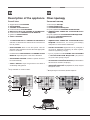
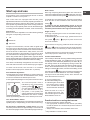
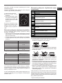
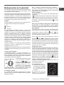
Description of the appliance
Overall view
1 Support Grid for COOKWARE
2 GAS BURNERS
3 CERAMIC GLASS MODULE*
4 Control Knobs for GAS BURNERS
5 INDICATOR LIGHT FOR CERAMIC GLASS MODULE*
6 Control Knobs for CERAMIC GLASS MODULE*
7 Ignition for GAS BURNERS*
8 SAFETY DEVICES*
• The INDICATOR LIGHT for CERAMIC GLASS MODULE
switches on whenever the selector knob is moved from
the ‘off’ position.
• GAS BURNERS differ in size and power. Use the
diameter of the cookware to choose the most appropriate
burner to cook with.
• Control Knobs for GAS BURNERS and CERAMIC GLASS
MODULE* adjust the power or the size of the ame.
• GAS BURNER IGNITION* enables a specic burner to
be lit automatically.
• SAFETY DEVICE* stops the gas ow if the ame is
accidentally extinguished.
* Only available on certain models.
Опис приладу
Загальний вигляд
1 Решітка для ПОСУДУ
2 ГАЗОВІ КОНФОРКИ
3 СКЛОКЕРАМІЧНИЙ МОДУЛЬ*
4 Ручки управління ГАЗОВИМИ КОНФОРКАМИ
5 ІНДИКАТОРНА ЛАМПОЧКА СКЛОКЕРАМІЧНОГО
МОДУЛЮ*
6 Ручки управління СКЛОКЕРАМІЧНИМ МОДУЛЕМ*
7 Запальник ГАЗОВИХ КОНФОРОК*
8 ЗАХИСНІ ПРИСТРОЇ*
• ІНДИКАТОРНА ЛАМПОЧКА СКЛОКЕРАМІЧНОГО
МОДУЛЯ* вмикається, як тільки ручка вибору
повертається в положення вимикання.
• ГАЗОВІ КОНФОРКИ відрізняються за розміром й
потужністю. Обирайте конфорку, на який готувати,
залежно від діаметру посуду.
• Ручки управління ГАЗОВИМИ КОНФОРКАМИ
й СКЛОКЕРАМІЧНИМ МОДУЛЕМ* регулюють
потужність або розмір полум’я.
• ЗАПАЛЬНИК ГАЗОВОЇ КОНФОРКИ* дає можливість
автоматично запалити конфорку.
• ЗАХИСНИЙ ПРИСТРІЙ* перекриває газ, якщо полум’я
випадково гасне.
* Використовується лише в деяких моделях.
1
1
4
4
2 2
4
8
7
3
6
5
1
2

7
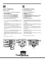
Opis urządzenia
Widok ogólny
1. Ruszty do ustawiania NACZYŃ DO GOTOWANIA
2. PALNIKI GAZOWE
3. PŁYTA CERAMICZNA*
4. Pokrętła sterujące PALNIKÓW GAZOWYCH
5. Kontrolka działania PŁYTY CERAMICZNEJ
6. Pokrętła sterujące PŁYTY CERAMICZNEJ*
7. Świeca zapłonowa PALNIKÓW GAZOWYCH*
8. URZĄDZENIA ZABEZPIECZAJĄCE*
• Kontrolka działania PŁYTY CERAMICZNEJ* zapala
się dla każdej pozycji pokrętła z wyjątkiem pozycji
wyłączenia.
• PALNIKI GAZOWE posiadają różne wymiary i moce.
Należy wybrać ten palnik, który jest najbardziej
odpowiedni dla średnicy używanego naczynia.
• Pokrętła sterowania PALNIKAMI GAZOWYMI oraz
PŁYTĄ CERAMICZĄ* służą do regulowania płomienia
lub mocy.
• Świeca zapłonowa PALNIKÓW GAZOWYCH* umożliwia
automatyczne zapalenie wybranego palnika.
• URZĄDZENIE ZABEZPIECZAJĄCE* w razie
przypadkowego zgaśnięcia płomienia przerywa dopływ
gazu.
* Tylko w niektórych modelach.
1
1
4
4
2 2
4
8
7
3
6
5
1
2
A készülék leírása
A készülék áttekintése
1 Tartórács a FŐZŐEDÉNYEKHEZ
2 GÁZÉGŐK
3 ÜVEGKERÁMIA MODUL*
4 A GÁZÉGŐK szabályzógombjai
5 AZ ÜVEGKERÁMIA MODUL VISSZAJELZŐ LÁMPÁI*
6 Az ÜVEGKERÁMIA MODUL* szabályzógombjai
7 A GÁZÉGŐK* gyújtója
8 BIZTONSÁGI ESZKÖZÖK*
• A ÜVEGKERÁMIA MODUL VISSZAJELZŐ LÁMPÁJA*
világítani kezd, ha a választókapcsolót elmozdítja „off”
(ki) állásból.
• A GÁZÉGŐK mérete és teljesítménye eltérő. A
főzőedény átmérője alapján válassza ki a főzéshez
leginkább megfelelő gázégőt
• A GÁZÉGŐK és az ÜVEGKERÁMIA MODUL*
szabályzógombjaival állíthatja be a teljesítményt vagy a
láng nagyságát.
• A GÁZÉGŐ GYÚJTÓJA* segítségével egy adott égőt
gyújthat be automatikusan.
• A BIZTONSÁGI ESZKÖZ* megállítja a gáz áramlását,
ha a láng véletlenül kialszik.
* Csak bizonyos modelleken elérhető.

8
GB
Installation
! Before operating your new appliance please read this
instruction booklet carefully. It contains important information
for safe use, installation and care of the appliance.
! Please keep these operating instructions for future reference.
Pass them on to possible new owners of the appliance.
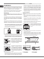
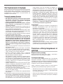
Positioning
! Keep packaging material out of the reach of children. It can
become a choking or suffocation hazard (see Precautions
and tips).
! The appliance must be installed by a qualied professional
according to the instructions provided. Incorrect installation
may cause harm to people and animals or may damage
property.
! This unit may be installed and used only in permanently
ventilated rooms in accordance with current national
regulations. The following requirements must be observed:
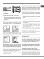
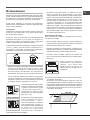
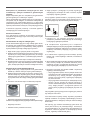
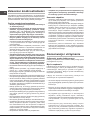
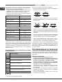
• The room must be equipped with an air extraction system
that expels any combustion fumes. This may consist of
a hood or an electric fan that automatically starts each
time the appliance is switched on.
In a chimney stack or branched flue.
(exclusively for cooking appliances)
Directly to
the Outside
• The room must also allow proper air circulation, as air is
needed for combustion to occur normally. The ow of air
must not be less than 2 m
3
/h per kW of installed power.
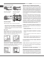
The air circulation system may
take air directly from the outside
by means of a pipe with an inner
cross section of at least 100 cm
2
;
the opening must not be vulnerable
to any type of blockages.
The system can also provide the air
needed for combustion indirectly,
i.e. from adjacent rooms tted with
air circulation tubes as described
above. However, these rooms must
not be communal rooms, bedrooms
or rooms that may present a re
hazard.
• Liquid petroleum gas sinks to the oor as it is heavier
than air. Therefore, rooms containing LPG cylinders must
also be equipped with vents to allow gas to escape in
A
Examples of
ventilation holes
for comburant air.
Enlarging the ventilation slot
between window and floor.
Adjacent
Room
Room to be
Vented
the event of a leak. As a result LPG cylinders, whether
partially or completely full, must not be installed or stored
in rooms or storage areas that are below ground level
(cellars, etc.). It is advisable to keep only the cylinder
being used in the room, positioned so that it is not subject
to heat produced by external sources (ovens, replaces,
stoves, etc. ) which could raise the temperature of the
cylinder above 50°C.
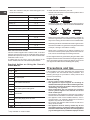
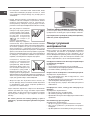
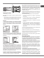
Fitting the appliance
The following precautions must be taken when installing
the hob:
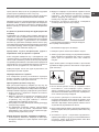
• Kitchen cabinets adjacent to the appliance and taller than
the top of the hob must be at least 600 mm from the edge
of the hob.
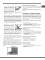
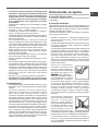
• Hoods must be installed according to their relative
installation instruction manuals and at a minimum
distance of 650 mm from the hob (see gure).
• Place the wall cabinets adjacent to the hood at a minimum
height of 420 mm from the hob (see gure).
If the hob is installed beneath a wall
cabinet, the latter must be situated
at a minimum of 700 mm above
the hob.
• The installation cavity should have the dimensions
indicated in the gure.
Fastening hooks are provided, allowing you to fasten
the hob to tops that are between 20 and 40 mm thick.
To ensure the hob is securely fastened to the top, we
recommend you use all the hooks provided.
555 mm
55 mm
475 mm
Hook fastening diagram
Hooking position Hooking position
for top H=20mm for top H=30mm
600mm min.
420mm min.
650mm min.

GB
9
Front
Hooking position Back
for top H=40mm
! Use the hooks contained in the “accessory pack”.
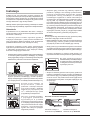
• Where the hob is not installed over a built-in oven, a
wooden panel must be installed as insulation. This must
be placed at a minimum distance of 20 mm from the lower
part of the hob.
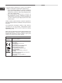
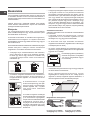
Ventilation
To ensure adequate ventilation, the back panel of the cabinet
must be removed. It is advisable to install the oven so that it
rests on two strips of wood, or on a completely at surface
with an opening of at least 45 x 560 mm (see diagrams).
560 mm.
45 mm.
Where a hob is installed above an oven without a forced
ventilation cooling system, adequate ventilation must be
provided inside the cabinet by means of air holes through
which air can pass (see gure).
Electrical connection
Hobs equipped with a three-pole power supply cable are
designed to operate with alternating current at the voltage and
frequency indicated on the data plate (this is located on the
lower part of the appliance). The earth wire in the cable has a
green and yellow cover. If the appliance is to be installed above
a built-in electric oven, the electrical connection of the hob and
the oven must be carried out separately, both for electrical
safety purposes and to make extracting the oven easier.
Connecting the supply cable to the mains
Install a standardised plug corresponding to the load
indicated on the data plate.
The appliance must be directly connected to the mains
using an omnipolar circuit-breaker with a minimum contact
opening of 3 mm installed between the appliance and the
mains. The circuit-breaker must be suitable for the charge
indicated and must comply with current electrical regulations
(the earthing wire must not be interrupted by the circuit-
breaker). The supply cable must not come into contact with
surfaces with temperatures higher than 50°C.
! The installer must ensure that the correct electrical
connection has been made and that it is compliant with
safety regulations.
Before connecting to the power supply, make sure that:
• The appliance is earthed and the plug is compliant with
the law.
• The socket can withstand the maximum power of the
appliance, which is indicated on the data plate.
• The voltage is in the range between the values indicated
on the data plate.
• The socket is compatible with the plug of the appliance.
If the socket is incompatible with the plug, ask an
authorised technician to replace it. Do not use extension
cords or multiple sockets.
! Once the appliance has been installed, the power supply
cable and the electrical socket must be easily accessible.
! The cable must not be bent or compressed.
! The cable must be checked regularly and replaced by
authorised technicians only (see Assistance).
! The manufacturer declines any liability should these safety
measures not be observed.
Gas connection
The appliance should be connected to the main gas supply
or to a gas cylinder in compliance with current national
regulations. Before carrying out the connection, make sure
the cooker is compatible with the gas supply you wish to
use. If this is not the case, follow the instructions indicated
in the paragraph “Adapting to different types of gas.”
When using liquid gas from a cylinder, install a pressure
regulator which complies with current national regulations.
! Check that the pressure of the gas supply is consistent with the
values indicated in Table 1 (“Burner and nozzle specications”).
This will ensure the safe operation and longevity of your
appliance while maintaining efcient energy consumption.
Connection with a rigid pipe (copper or steel)
! Connection to the gas system must be carried out in such a
way as not to place any strain of any kind on the appliance.
There is an adjustable L-shaped pipe tting on the appliance
supply ramp and this is tted with a seal in order to prevent
leaks. The seal must always be replaced after rotating the
pipe tting (seal provided with appliance). The gas supply
pipe tting is a threaded 1/2 gas cylindrical male attachment.

10
GB
Connecting a exible jointless stainless steel pipe to a
threaded attachment
The gas supply pipe tting is a threaded 1/2 gas cylindrical
male attachment.
These pipes must be installed so that they are never longer
than 2000 mm when fully extended. Once connection has
been carried out, make sure that the exible metal pipe
does not touch any moving parts and is not compressed.
! Only use pipes and seals that comply with current national
regulations.
Checking the tightness of the connection
! When the installation process is complete, check the pipe
ttings for leaks using a soapy solution. Never use a ame.
Adapting to different types of gas
To adapt the hob to a different type of gas other than default
type (indicated on the rating plate at the base of the hob or
on the packaging), the burner nozzles should be replaced
as follows:
1. Remove the hob grids and slide the burners off their
seats.
2. Unscrew the nozzles using a 7 mm socket spanner, and
replace them with nozzles for the new type of gas (see
table 1 “Burner and nozzle characteristics”).
3. Reassemble the parts following the above procedure in
the reverse order.
4. Once this procedure is nished, replace the old rating
sticker with one indicating the new type of gas used.
Sticker are available from any of our Service Centres.
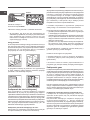
Replacing the nozzles on separate “double ame “
burners
1. Remove the grids and slide the burners from their
housings. The burner consists of 2 separate parts (see
gure);
2. Unscrew the burers with a 7 mm wrench spanner. The
internal burner has a nozzle, the external burner has
two (of the same size). Replace the nozzle with models
suited to the new type of gas (see table 1).
3. Replace all the components by repeating the steps in
reverse order.
• Adjusting the burners’ primary air
Does not require adjusting.
• Setting the burners to minimum
1. Turn the tap to the low ame position;
2. Remove the knob and adjust the adjustment screw, which
is positioned in or next to the tap pin, until the ame is
small but steady.
! In the event of single-control DRDA (DCDR) burners,
adjustment can be performed by intervening on the 2 screws
located near the tap pin (see picture).
Inner DRDA (DCDR)
burner adjustment
Total DRDA
(DCDR) burner
adjustment
3. Having adjusted the ame to the required low setting,
while the burner is alight, quickly change the position
of the knob from minimum to maximum and vice versa
several times, checking that the ame does not go out.
4. Some appliances have a safety device (thermocouple)
tted. If the device fails to work when the burners are set
to the low ame setting, increase this low ame setting
using the adjusting screw.
5. Once the adjustment has been made, replace the
seals on the by-passes using sealing wax or a similar
substance.
6. In the event of discrete-adjustment knobs with LED
visualisation, turn the knob to the minimum power setting
them remove it and intervene on the adjustment screw
located near the tap pin.
7. Minimum setting adjustment of the DRDA (DCDR) burner
with discrete adjustment and LED visualisation:
• To adjust the total burner, turn the knob anti-clockwise
to the minimum power position. Remove the knob and
intervene on the adjustment screw located near the
tap pin.
• To adjust the minimum power setting of the inner ring,
turn the knob clockwise to the minimum power position.
Remove the knob and intervene on the adjustment
screw located near the tap pin.
! If the appliance is connected to liquid gas, the regulation
screw must be fastened as tightly as possible.
! Once this procedure is nished, replace the old rating
sticker with one indicating the new type of gas used. Stickers
are available from any of our Service Centres.
! Should the gas pressure used be different (or vary slightly)
from the recommended pressure, a suitable pressure
regulator must be tted to the inlet pipe (in order to comply
with current national regulations).

GB
11
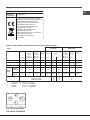
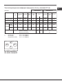
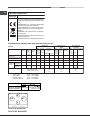
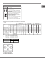
Table 1 Liquid Gas Natural Gas
Burner Diameter Thermal Thermal By-pass Nozzle Flow* Thermal Nozzle Flow*
power power 1/100 1/100 (g/h) power 1/100 (l/h)
kW kW kW
(p.c.s.*) (p.c.s.*) (p.c.s.*)
(mm) Reduced Nominal (mm) (mm) *** ** Nominal (mm)
Supply pressures
Nominal (mbar)
Minimum (mbar)
Maximum (mbar)
28-30
20
35
37
25
45
20
17
25
Reduced Fast (RR)
Semi Fast (S)
Auxiliary (A)
100
75
55
0.70
0.40
0.40
2.60
1.65
1.00
39
28
28
80
64
50
189
120
73
186
118
71
2.60
1.65
1.00
122(H3)
96(Z)
79(6)
248
157
95
Double
flame
DCDR
internal
DCDR
TOTAL
Burner and nozzle specifications (for 65 cm versions only)
* At 15°C and 1013,25 mbar - dry gas
** Propane P.C.S. = 50.37 MJ/Kg
*** Butane P.C.S. = 49.47 MJ/Kg
Natural P. C.S. = 37.78 MJ/m³
30
130
0.40
1.65
0.90
3.60
27
55
44
60x2+44
65
262
64
257
0.90
3.60
74
94x2+74
86
343
Electrical
connections
DATA PLATE
see data plate
This appliance conforms to the following
European Economic Community directives:
- 2006/95/EEC dated 12/12/06 (Low
Voltage) and subsequent amendments
- 2004/108/EEC dated 15/12/04
(Electromagnetic Compatibility) and
subsequent amendments
- 93/68/EEC dated 22/07/93 and
subsequent amendments.
- 2009/142/EEC dated 30/11/09 (Gas) and
subsequent amendments.
- 2012/19/EC and subsequent
amendments.
PK 640 R GH/HA EE
PK 640 RL GH/HA EE
RR
DC
S
A

12
GB
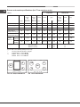
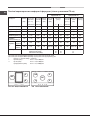
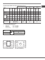
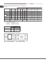
Table 1 Liquid Gas Natural Gas
Burner Diameter Thermal Thermal By-pass Nozzle Flow* Thermal Nozzle Flow*
power power 1/100 1/100 (g/h) power 1/100 (l/h)
kW kW kW
(p.c.s.*) (p.c.s.*) (p.c.s.*)
(mm) Reduced Nominal (mm) (mm) *** ** Nominal (mm)
Supply pressures
Nominal (mbar)
Minimum (mbar)
Maximum (mbar)
28-30
20
35
37
25
45
20
17
25
Reduced Fast (RR)
Semi Fast (S)
Auxiliary (A)
Double Flame
(DCDR Internal) (2)
Double Flame
(DCDR External) (2)
100
75
55
30
130
0.80
0.45
0.45
0.45
1.65
2.70
1.75
1.05
0.90
3.90
39
28
28
28
61
80
64
50
44
70x2
196
127
76
65
284
193
125
75
64
279
2.70
1.75
1.05
0.90
3.90
122(H3)
96(Z)
79(6)
74
107x2
257
167
100
86
371
Double
flame (1)
DCDR
internal
DCDR
TOTAL
Burner and nozzle specifications (for 75 cm versions only)
(1) For single-control DRDA (DCDR) burner only
(2) For dual-control DRDA (DCDR) burner only
* At 15°C and 1013,25 mbar - dry gas
** Propane P.C.S. = 50.37 MJ/Kg
*** Butane P.C.S. = 49.47 MJ/Kg
Natural P.C.S. = 37.78 MJ/m³
30
130
0.40
1.65
0.90
3.90
27
55
44
65x2+44
65
284
64
279
0.90
3.90
72
96x2+72
86
371
PK 741 RQO GH/HA EE
DC
S
A
PK 750 R GH/HA EE
RR
DC
S
S
A

GB
13
Start-up and use
! The position of the corresponding gas burner or electric
hotplate* is shown on every knob.
Gas cooker hobs are equipped with discrete power
adjustment that allows for accurately adjusting the ame to 5
different power levels. Thanks to this system, gas hobs are
also capable of guaranteeing the same cooking results for
each recipe, as the optimal power level for the desired type
of cooking can be identied in an easier, more accurate way.
Gas burners
Each burner can be adjusted to one of the following settings
using the corresponding control knob:
● Off
Maximum
Minimum
To light one of the burners, hold a lit match or lighter near
the burner and, at the same time, press down and turn the
corresponding knob anti-clockwise to the maximum setting.
Since the burner is tted with a safety device, the knob
should be pressed for approximately 2-3 seconds to allow
the automatic device keeping the ame alight to heat up.
When using models with an ignition button, light the desired
burner pressing down the corresponding knob as far as possible
and turning it anticlockwise towards the maximum setting.
! If a ame is accidentally extinguished, turn off the control
knob and wait for at least 1 minute before trying to relight it.
To switch off the burner, turn the knob in a clockwise
direction until it stops (when reaches the “●” position).
Discrete ame adjustment
The selected burner can be adjusted - by means of the knob
- to 5 different power levels. To shift between levels, simply
turn the knob towards the desired power level.
A click signals the passage from one power level to the other.
The selected power level is
indicated by the corresponding
symbol (symbols ) and,
on hobs equipped with a display,
by the LEDs that turn on (5 =
max. power; 1 = min. power). The
system guarantees accurate ame
adjustment and uniform cooking
results by facilitating selection of the desired power level.
The “double-ame” burner
This gas burner consists of two concentric ame rings that can
operate jointly or independently (in case of dual-control only).
As the burner is tted with a safety device, the knob
should be pressed down for approximately 2-3 seconds until
the device keeping the ame automatically alight heats up.
Dual control:
Each ring comprising the burner has its own control knob:
The knob marked with the symbol controls the outer ring.
The knob marked with the symbol controls the inner ring.
To activate any one of the two rings, press the corresponding
knob and turn it anti-clockwise to the maximum power
setting .
In order to use the double-flame burner to its full
potential, avoid simultaneously setting the inner ring to
minimum power and the outer ring to maximum power.
Single control:
The rings comprising the burner are activated through a
single control knob.
To simultaneously turn on both rings, position the knob on
the symbol (max) - (min) then press and turn the
knob anti-clockwise.
To turn on the inner ring only, position the knob on the symbol
(max ) - (min) then press and turn the knob clockwise.
(to switch modes, it is necessary to switch off the burner).
To switch off the burner, press and turn the knob clockwise
until it stops (when it reaches the “●” position).
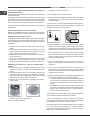
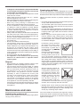
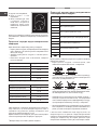
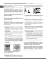
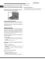
Ceramic Glass Module*
This cooktop is tted with dual-ring radiant heating elements
located beneath the glass. It is possible to turn on only the
circular part of the elemement (identied by the letter “A”) or
the cooking surface can be enlarged by turning on both “A”
and “B”. To turn only the circular “A” element, simply turn the
knob in the clockwise direction to any one of the 12 available
settings. To add the “B” section, turn the knob to setting 12 and
then click it into the setting. Then proceed by turning the knob
in the counter-clockwise direction to one of the 12 settings.
The gure shows the heating zones, which become red
when the element is turned on.
A. Circular heating zone;
B. Extended heating zone;
C. Indicator light to show when
the cooking zone is above
60°C, even after the heating
element has been turned off.
When the knob is on any of
the settings other than “Off”,
the Indicator Light for Ceramic
Glass Module comes on.
Practical advice on using the burners
To ensure the burners operate efciently:
• Use appropriate cookware for each burner (see table)
so that the ames do not extend beyond the bottom of
the cookware.
• Always use cookware with a at base and a cover.
A
C
B
* Only available on certain models.

14
GB
• When the contents of the pan reach boiling point, turn
the knob to minimum.
Burner
Reduced Fast (RR)
Semi Fast (S)
Auxiliary (A)
Double Flame (DCDR internal)
Double Flame (DCDR external)
Ø Cookware Diameter (cm)
24 - 26
16 - 20
10 - 14
10 - 14
26 - 28
Pans to be used on 75 cm hobs
Burner
Reduced Fast (RR)
Semi Fast (S)
Auxiliary (A)
Double Flame (DCDR internal)
Double Flame (DCDR external)
Ø Cookware Diameter (cm)
24 - 26
16 - 20
10 - 14
10 - 14
24 - 26
Pans to be used on 65 cm hobs
! On the models supplied with a reducer shelf, remember
that this should be used only for the Double ame internal
(DCDR internal) burner when you use casserole dishes with
a diameter under 12 cm.
To identify the type of burner, refer to the designs in the
section entitled, “Burner and Nozzle Specications”.
Practical Advise on Using the Ceramic
Glass Module*
Set.
0
1
2
3
4
5
6
7
8
9
10
11
12
Radiant Burner
Off.
To melt butter and chocolate.
To heat liquids.
For creams and sauces.
For cooking at the boiling point.
For Roasts.
For boiling large pieces of meat.
For frying.
For utilising both cooking areas.
To obtain the best results from your hob:
• Use at-bottomed pans to ensure that they adhere to the
cooking zone perfectly.
• Always use pans with a diameter that is large enough to
cover the hotplate fully, in order to use all the available heat.
• Make sure that the bottom of the cookware is always dry
and clean to guarantee correct adherence and long life, not
only for the cooking zones but also for the cookware itself.
• Avoid using the same cookware that is used on gas burners:
the heat concentration on gas burners may deform the base
of the pan, causing it not to adhere correctly.
• Never leave a cooking zone on without cookware on it
because as it heats up and rapidly reaches the maximum
level, which could damage the heating elements.
! There might be traces of grease left by the glue used to seal
the glass which should be removed before using the appliance
with a mild cleaning product. During the rst few hours of use
you might smell rubber but this will disappear quickly.
Precautions and tips
! This appliance has been designed and manufactured
in compliance with international safety standards. The
following warnings are provided for safety reasons and
must be read carefully.
General safety
• This is a class 3 built-in appliance.
• Gas appliances require regular air exchange to
maintain efcient operation. When installing the hob,
follow the instructions provided in the paragraph on
“Positioning” the appliance.
• These instructions are only valid for the countries
whose symbols appear in the manual and on the
serial number plate.
• The appliance was designed for domestic use inside the
home and is not intended for commercial or industrial use.
• The appliance must not be installed outdoors, even in
covered areas. It is extremely dangerous to leave the
appliance exposed to rain and storms.
• Do not touch the appliance with bare feet or with wet or
damp hands and feet.
• The appliance must be used by adults only for the
preparation of food, in accordance with the instructions
outlined in this booklet. Any other use of the appliance
(e.g. for heating the room) constitutes improper use and
* Only available on certain models.

GB
15
is dangerous. The manufacturer may not be held liable
for any damage resulting from improper, incorrect and
unreasonable use of the appliance.
• The openings used for ventilation and dispersion of heat
must never be covered.
• Always make sure the knobs are in the “●”/“○” position
when the appliance is not in use.
• When unplugging the appliance always pull the plug from
the mains socket, do not pull on the cable.
• Never carry out any cleaning or maintenance work
without having detached the plug from the mains.
• In case of malfunction, under no circumstances should
you attempt to repair the appliance yourself. Repairs
carried out by inexperienced persons may cause injury
or further malfunctioning of the appliance. Contact a
Service Centre (see Assistance).
• Always make sure that pan handles are turned towards
the centre of the hob in order to avoid accidental burns.
• Do not close the glass cover (if present) when the gas
burners or electric hotplates are still hot.
• Do not leave the electric hotplate switched on without a
pan placed on it.
• Do not use unstable or deformed pans.
• The appliance should not be operated by people
(including children) with reduced physical, sensory or
mental capacities, by inexperienced individuals or by
anyone who is not familiar with the product. These
individuals should, at the very least, be supervised by
someone who assumes responsibility for their safety or
receive preliminary instructions relating to the operation
of the appliance.
• Do not let children play with the appliance.
• The appliance is not intended to be operated by
means of an external timer or separate remote-
control system.
Disposal
• When disposing of packaging material: observe local
legislation so that the packaging may be reused.
• The European Directive 2012/19/EC on Waste
Electrical and Electronic Equipment (WEEE), requires
that old household electrical appliances must not
be disposed of in the normal unsorted municipal
waste stream. Old appliances must be collected
separately in order to optimise the recovery and
recycling of the materials they contain and reduce
the impact on human health and the environment.
The crossed out “wheeled bin” symbol on the product
reminds you of your obligation, that when you dispose
of the appliance it must be separately collected.
Consumers should contact their local authority or retailer
for information concerning the correct disposal of their
old appliance.
Maintenance and care
Switching the appliance off
Disconnect your appliance from the electricity supply before
carrying out any work on it.
Cleaning the appliance
! Do not use abrasive or corrosive detergents such as stain
removers, anti-rust products, powder detergents or sponges with
abrasive surfaces: these may scratch the surface beyond repair.
! Never use steam cleaners or pressure cleaners on the
appliance.
• It is usually enough to wash the hob with a damp sponge
and dry it with absorbent kitchen roll.
• The removable parts of the burners should be washed
frequently with warm water and soap and any burnt-on
substances removed.
• For hobs which ligth automatically, the terminal part of
the electronic instant lighting devices should be cleaned
frequently and the gas outlet holes should be checked
for blockages.
• Before using the ceramic glass module, the surface
must be cleaned, using a damp cloth to remove dust
or food residues. The ceramic glass surface should be
cleaned regularly with a soultion of warm water and a
non-abrasive detergent.
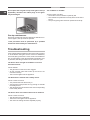
Periodically, special products
will need to be used to clean
the surface. First, remove all
food buildup or grease with a
cleaning scraper, e.g.
(not supplied).
Clean the cooking surface when
it is still warm with a suitable
cleaning product (such as the
one in the Solutions product line available from any
After-Sales Service Centre) and paper towels. Then rub
with a damp cloth and dry. Aluminum foil, plastic items,
objects made of synthetic material, sugar or foods with
a high sugar content that have melted onto the surface
must be removed immediatley with a scraper while the
cooking surface is still hot.
Special cleaning products for
ceramic glass surfaces form
a transparent protective layer
which ghts diry buildup. This
also protects the surface from
damage caused by food with
a high sugar content. Do not
use abrasive sponges or
cleaning products under any
circumstances. This holds true for chemically aggressive
cleaners, like oven sprays and stain removers.
• Stainless steel can be marked by hard water that has
been left on the surface for a long time, or by aggressive
detergents containing phosphorus. After cleaning, rinse
and dry any remaining drops of water.
! It is not necessary to remove the pan supports in order to
clean the hob surface. Thanks to the support system, simply
lift and hold the pan supports or rotate them until they rest
against a rear support.

16
GB
Do not place the hot grids on top of the glass cover (if
applicable), otherwise the rubber plugs on the glass
may be damaged.
Gas tap maintenance
Over time, the taps may become jammed or difcult to turn.
If this happens, the tap must be replaced.
! This procedure must be performed by a qualied
technician authorised by the manufacturer.
Troubleshooting
It may happen that the appliance does not function properly
or at all. Before calling the service centre for assistance,
check if anything can be done. First, check to see that there
are no interruptions in the gas and electrical supplies, and,
in particular, that the gas valves for the mains are open.
The burner does not light or the ame is not even
around the burner.
Check whether:
• The gas holes on the burner are clogged.
• All the movable parts that make up the burner are
mounted correctly.
• There are draughts near the appliance.
The ame dies in models with a safety device.
Check to make sure that:
• You pressed the knob all the way in.
• You keep the knob pressed in long enough to activate
the safety device.
• The gas holes are not blocked in the area corresponding
to the safety device.
The burner does not remain lit when set to minimum.
Check to make sure that:
• The gas holes are not blocked.
• There are no draughts near the appliance.
• The minimum setting has been adjusted properly.
The cookware is unstable.
Check to make sure that:
• The bottom of the cookware is perfectly at.
• The cookware is positioned correctly at the centre of the
burner.
• The pan support grids have been positioned correctly.

UA
17
Встановлення
! Перш ніж користуватися Вашим новим приладом, будь
ласка, уважно ознайомтеся з інструкціями в цій брошурі.
В ній міститься важлива інформація щодо безпечного
встановлення, експлуатації і догляду за приладом.
! Будь ласка, збережіть ці інструкції для подальшого
використання. Передавайте їх разом з приладом будь-
якому новому власнику.
Розміщення
! Зберігайте пакувальні матеріали в недоступному для
дітей місці. Це небезпечно: існує ризик задухи (див.
Застереження й поради).
! Прилад має встановлюватися кваліфікованим
фахівцем відповідно до інструкцій, що додаються.
Порушення правил установлення може травмувати
людей і тварин або може зашкодити майну.
! Цей прилад можна встановлювати й використовувати
тільки у добре вентильованих приміщеннях у
відповідності з діючими національними правилами.
Необхідно дотримуватися наступних вимог:
В димохід або відвід системи димоходів
(тільки для кухонних приладів)
Безпосередньо
назовні
• Приміщення має бути оснащене системою витягування
повітря, яка видаляє всі продукти горіння. Така
система може складатися з витяжного ковпака
або електричного вентилятора, що запускається
автоматично кожного разу, коли вмикається прилад.
• Також необхідно забезпечити належну циркуляцію
повітря в приміщенні, оскільки повітря потрібне для
належного горіння. Потік повітря має бути не менше
2 м
3
/годину на кВт установленої потужності.
Система циркуляції повітря може
забирати повітря безпосередньо
з вулиці за допомогою труби
з внутрішнім перетином не
менше 100 см
2
; отвір має бути
захищеним від закупорювання
будь-якого типу.
Система також може забезпечувати
повітря, необхідне для горіння,
опосередковано, тобто з
прилеглих приміщень, оснащених
повітрозабірними трубами, як
описано вище. Однак ці приміщення
не мають бути кімнатами
комунального призначення,
спальнями або кімнатами з
пожежонебезпечною атмосферою.
A
Приклади вентиляційних
отворів для відводу повітря з
продуктами горіння.
Збільшений вентиляційний
отвір між вікном і підлогою
Сусіднє
приміщення
Приміщення, що
має вентилюватися
• Зріджений вуглеводневий газ збирається біля
підлоги, оскільки він є більш важким, ніж повітря.
Тому приміщення, де зберігаються балони ЗВГ, також
мають оснащуватися вентиляційними отворами для
забезпечення виведення газу в разі витоку. З цієї
причини балони зрідженого газу, як частково, так
і повністю наповнені, не слід установлювати або
зберігати в приміщеннях, що знаходяться нижче за
рівень землі (підвал, тощо). Рекомендовано тримати в
приміщенні тільки той балон, яким Ви безпосередньо
користуєтеся, так щоб не допустити його нагрівання
від зовнішніх джерел тепла (плити, каміни, печі, тощо)
до температури вище 50°C.
Налаштування приладу
При встановленні поверхні дотримуйтеся наступних
застережних заходів:
• Кухонні шафи поблизу приладу й вищі за варильну
поверхню мають розміщуватися на відстані не менше
600 мм від краю варильної поверхні.
• Ковпаки необхідно встановлювати, дотримуючись
відповідних інструкцій з установлення на мінімальній
відстані 650 мм від поверхні (див. малюнок).
• Розмістіть настінні шафи, прилеглі до ковпака, на
висоті не менше 420 мм від варильної поверхні (див.
малюнок).
Якщо варильна поверхня
встановлюється під настінною
шафою, така шафа має
навішуватися на висоті не
менше 700 мм над варильною
поверхнею.
Отвір в кухонній робочій поверхні повинен мати розміри,
що вказані на малюнку.
В комплект постачання входять кріпильні гачки, що
дають Вам можливість закріпити варильну поверхню
на кухонній робочій поверхні товщиною 20-40 мм. Щоб
забезпечити надійне кріплення на робочій поверхні,
ми рекомендуємо використати всі гачки, що входять
в комплект постачання.
555 mm
55 mm
475 mm
600mm min.
420mm min.
650mm min.

18
UA
Схема кріплення на гачках
Положення гачків для Положення гачків для
поверхні H = 20 мм поверхні H = 30 мм
Спереду
Положення гачків для Ззаду
поверхні H = 40 мм
! Використовуйте гачки з “комплекту аксесуарів”
• Якщо поверхня не встановлюється над вбудованою
духовкою, для ізоляції необхідно використовувати
дерев’яну панель. Така панель має розміщуватися
на відстані не менше 20 мм від нижньої частини
варильної поверхні.
Вентиляція
Щоб гарантувати достатню вентиляцію, задню панель
шафи необхідно зняти. Рекомендовано встановити
духовку таким чином, щоб вона спиралася на дві
дерев’яні планки або на абсолютно рівну поверхню з
отвором не менше 45 x 560 мм (див. схему).
560 mm.
45 mm.
При встановленні варильної поверхні над вбудованою
духовкою без примусової вентиляційної системи
охолодження, необхідно забезпечити належну
вентиляцію всередині шафи за рахунок отворів, крізь
які може проходити повітря (див. малюнок).
Підключення до електричної мережі
Варильні поверхні, оснащені трифазним кабелем
живлення призначеним для підключення до мережі
змінного струму з напругою й частотою, які вказані на
табличці з даними (що знаходиться в нижній частині
приладу). Провід заземлення в кабелі має зелено-жовту
оболонку. Якщо прилад встановлюється над вбудованою
електричною духовкою, електричне з’єднання варильної
поверхні й духовки слід виконувати окремо, що необхідно
як у цілях безпеки, так і для спрощення зняття духовки
в разі потреби.
Підключення кабелю живлення до електричної мережі
Установіть стандартну вилку, що відповідає
навантаженню, яке вказане на табличці технічних даних.
Прилад необхідно підключити безпосередньо до мережі
з використанням пакетного вимикача з мінімальним
контактним отвором 3 мм, що встановлюється між
приладом и мережею. Вимикач має відповідати
вказаному заряду й діючим нормам улаштування
електричних установок (вимикач не має від’єднувати
провід заземлення). Кабель живлення не має контактувати
з поверхнями, температура яких вище за 50°C.
! Фахівець, що встановлює прилад, має забезпечити
правильне електричне приєднання відповідно до
норм безпеки. Перед підключенням до електромережі
переконайтеся, що:
• Прилад заземлений і вилка кабелю відповідає
нормативним вимогам.
• Розетка може витримати максимальну потужність
приладу, яка вказана на табличці з технічними
даними.
• Напруга знаходиться в межах значень, вказаних на
табличці даних.
• Розетка сумісна з вилкою приладу. Якщо розетка не
сумісна з вилкою, попросіть фахівця замінити її. Не
використовуйте подовжувачі або декілька розеток.
! Після встановлення приладу необхідно забезпечити
безперешкодний доступ до шнуру живлення й
електричної розетки.
! Кабель живлення не можна перегинати або стискати.
! Кабель живлення необхідно регулярно перевіряти, а
його заміну має проводити лише технічний фахівець
(див. “Сервісна допомога”).
! Виробник знімає з себе будь-яку відповідальність у разі
недотримання цього правила техніки безпеки.
Під’єднання до джерела газопостачання
Приєднання до мережі газопостачання або до газового
балону необхідно виконувати у відповідності до
чинного законодавства в країні використання приладу.
Перед підключенням переконайтеся, що плита
сумісна з джерелом газопостачання, яким Ви бажаєте

UA
19
користуватися. Якщо це не так, дотримуйте інструкцій в
розділі “Пристосування до іншого типу газу”.
При користуванні зрідженим газом з балону встановіть
регулятор тиску, який відповідає місцевим нормам.
! Перевірте тиск газу: він має відповідати значенням, що
вказані в Таблиці 1 (“Технічні характеристики конфорок і
форсунок”). Це забезпечить безпечну й тривалу роботу
Вашого приладу й, одночасно, допоможе збереженню
енергії.
З’єднання за допомогою жорсткої труби (мідної або
сталевої)
! Приєднання до системи газопостачання виконується
таким чином, щоб не завдавати навантаження на будь-які
прилади. На рамі приладу передбачений регульований
L-подібний патрубок з ущільненням, що запобігає
витокам. Це ущільнення необхідно міняти кожного разу
після обертання патрубка (ущільнення входить в комплект
постачання приладу). Фітинг патрубка підведення газу є
циліндричнім і має зовнішню нарізку 1/2.
Приєднання гнучкої безфланцевої трубки з
нержавіючої сталі до нарізного з’єднання
Фітинг патрубка підведення газу є циліндричнім і має
зовнішню нарізку 1/2. Трубка має встановлюватися таким
чином, щоб її довжина у повністю витягнутому вигляді
не перевищувала 2000 мм. Після виконання приєднання
переконайтеся, що гнучка металева трубка не торкається
жодних частин, що рухаються, й не стискається.
! Використовуйте тільки такі труби й ущільнення, які
відповідають діючим нормам.
Перевірка щільності з’єднання
! По завершенні процесу встановлення перевірте
фітинги патрубку на витоки за допомогою мильного
розчину. Ніколи не користуйтеся вогнем.
Пристосування до іншого типу газу
Щоб пристосувати варильну поверхню до типу газу, що
відрізняється від заводської настройки (яка вказана на
табличці даних знизу варильної поверхні або на пакуванні),
необхідно замінити форсунку конфорки наступним чином:
1. Зніміть решітку з варильної поверхні й витягніть
конфорки з їх гнізд.
2. Відкрутіть форсунки за допомогою торцевого ключа
7 мм і замініть їх на форсунки, що відповідають
потрібному типу газу (див. Таблицю 1 “Технічні
характеристики конфорок і форсунок”).
3. Знову зберіть частини, виконуючи описану процедуру
в зворотному порядку.
4. По завершенні процедури, замініть стару етикетку
з даними про тип газу новою з відповідною новою
інформацією. Такі етикетки можна отримати в будь-
якому нашому сервісному центрі.
Заміна форсунок окремих “подвійних” конфорок
1. Зніміть решітку й витягніть конфорки зі своїх гнізд.
Конфорка складається з двох окремих частин (див.
малюнок).
2. Відкрутіть конфорки за допомогою торцевого ключа
7 мм. Внутрішня конфорка має форсунку, зовнішня
конфорка – дві форсунки (однакового розміру).
Замініть форсунку на іншу, модель якої відповідає
новому типу газу (див. таблицю 1).
3. Встановіть на місце всі компоненти, повторюючи
описані кроки в зворотньому порядку.
• Налаштування первинного повітря конфорки
Не потребує налаштування.
• Встановлення форсунок на мінімум
1. Поверніть кран в положення слабкого полум'я.
2. Зніміть ручку крана й підкрутіть регулювальний гвинт,
який знаходиться всередині або поряд із штирком
крана, доки не отримаєте мале, але стабільне
полум’я.
! Для налаштування конфорок DCDR з однотипним
управлінням відрегулюйте 2 гвинти біля штирка крана
(див. малюнок).
Внутрішнє
регулювання
конфорки DRDA
(DCDR)
Загальне
регулювання
конфорки DRDA
(DCDR)
3. Після налаштування вогню до потрібної малої
інтенсивності, поки конфорка горить, швидко
змініть положення ручки з мінімального полум’я на
максимальне й навпаки декілька разів, перевіряючи,
чи не згасає при цьому конфорка.
4. На деяких приладах встановлений захисний
пристрій (термопара). Якщо прилад не працює, коли
конфорка встановлена на позначці слабкого вогню,
збільшить відповідне налаштування слабкого вогню
за допомогою регулювального гвинта.
5. Після налаштування замініть ущільнення на байпасах,
використовуючи віск для герметизації або аналогічну
речовину.
6. За наявності ручок з покроковим керуванням і
індикатором поверніть ручку до позначки мінімальної
потужності, зніміть ручку й відрегулюйте гвинт біля
штирка крана (див. малюнок).

20
UA
7. Налаштування мінімального полум'я на конфорці
DCDR з покроковим управлінням і індикатором:
• Для регулювання загального пальник поверніть
ручку проти годинникової стрілки до положення
мінімальної потужності. Зніміть ручку й відрегулюйте
гвинт біля штирка крана.
• Для регулювання мінімального полум'я на
внутрішньому кільці поверніть ручку за
годинниковою стрілкою до положення мінімальної
потужності.Зніміть ручку й відрегулюйте гвинт біля
штирка крана.
! Якщо прилад підключений до джерела зрідженого
газу, регулювальний гвинт необхідно затягнути якомога
щільніше.
! По завершенні процедури, замініть стару етикетку
з даними про тип газу новою з відповідною новою
інформацією. Такі етикетки можна отримати в нашому
сервісному центрі.
! Якщо тиск газу відрізняється (або трішки відхиляється)
від рекомендованого значення, необхідно встановити
прийнятний регулятор тиску на вході труби (щоб
задовольнити діючим місцевим нормам).
Електричні
з'єднання
Таблиця
(дивіться таблицю)
Дана плита відповідає наступним
директивам
Європейського економічного
співтовариства:
- 2006/95/ЄЕC від 12/12/06 (Низька
Напруга) інаступні поправки
- 2004/108/ЄEC від15/12/04
(Електромагнітна Сумісність) та
наступніпоправки
- 93/68/ЄЕС від 22/07/93 та наступні
поправки.
- 90/336/ЄEC від 29/06/90 (Газ) і наступні
зміни та доповнення.
- 2012/19/ЄC і наступні зміни та
доповнення.
Strona się ładuje...
Strona się ładuje...
Strona się ładuje...
Strona się ładuje...
Strona się ładuje...
Strona się ładuje...
Strona się ładuje...
Strona się ładuje...
Strona się ładuje...
Strona się ładuje...
Strona się ładuje...
Strona się ładuje...
Strona się ładuje...
Strona się ładuje...
Strona się ładuje...
Strona się ładuje...
Strona się ładuje...
Strona się ładuje...
Strona się ładuje...
Strona się ładuje...
Strona się ładuje...
Strona się ładuje...
Strona się ładuje...
Strona się ładuje...
-
 1
1
-
 2
2
-
 3
3
-
 4
4
-
 5
5
-
 6
6
-
 7
7
-
 8
8
-
 9
9
-
 10
10
-
 11
11
-
 12
12
-
 13
13
-
 14
14
-
 15
15
-
 16
16
-
 17
17
-
 18
18
-
 19
19
-
 20
20
-
 21
21
-
 22
22
-
 23
23
-
 24
24
-
 25
25
-
 26
26
-
 27
27
-
 28
28
-
 29
29
-
 30
30
-
 31
31
-
 32
32
-
 33
33
-
 34
34
-
 35
35
-
 36
36
-
 37
37
-
 38
38
-
 39
39
-
 40
40
-
 41
41
-
 42
42
-
 43
43
-
 44
44


Hotpoint Ariston PK 741 RQO GH /HA EE instrukcja
- Typ
- instrukcja
- Niniejsza instrukcja jest również odpowiednia dla
Powiązane artykuły
Inne dokumenty
-
Indesit 642 PR /I(BK) instrukcja
-
HOTPOINT/ARISTON PC 640T(AN) R /HA PL instrukcja
-
Whirlpool KIT PC (PL) instrukcja
-
-
-
-
Whirlpool TG 752 (IX) GH instrukcja
-
-
-