
GB
Cordless Brushcutter/ Instruction Manual
Cordless String Trimmer
D Akku-Freischneider/ Betriebsanleitung
Akku-Rasentrimmer
PL Kosa akumulatorowa/ Instrukcja obsługi
Wykaszarka akumulatorowa
HU Vezeték nélküli fűnyíró/ Használati utasítás
Vezeték nélküli szegélynyíró
RO Motocoasă pentru tufişuri fără cablu/ Manual de instrucţiuni
Motocoasă cu fir fără cablu
SK Akumulátorový krovinorez/ Návod na obsluhu
Akumulátorová strunová kosačka
CZ Akumulátorový křovinořez/ Návod k obsluze
Akumulátorová strunová sekačka
UA Акумуляторний кущоріз/ Інструкція з експлуатації
Aкумуляторна кордова
газонокосарка
AT-3623
AT-3630
AT-3624
AT-3631
010751

2
1 013122 2 013863
3 013864 4 010752
5 011728 6 011731
7 011729 8 011732
1
2
3
AT-3623/AT-3624
4
5
AT-3630/AT-3631
4
5
AT-3623/AT-3624
6, 7, 8
A
B
AT-3630/AT-3631
6, 7, 8
A
B

3
9 011730 10 011733
11 010765 12 010770
13 011715 14 012456
15 011485 16 013123
AT-3623/AT-3624
9
AT-3630/AT-3631
9
1
2
10
11
12
13
14
16
15
17
18
19
20
22
21
14
23

4
17 013140 18 010768
19 012457 20 010778
21 010777 22 010849
23 010756 24 010757
24
25
26
25
27
28
29
30
31
25
25
27
32
24
34
35
36
33
32

5
25 010758 26 010769
27 010753 28 010760
29 010759 30 012478
31 010767 32 010816
37
32
33
38
39
40

6
33 010817 34 012479
35 010812 36 010772
37 010992 38 010993
39 010994 40 010776
40
41
42
43
44
45
45
46
47
80 mm
48
100 mm
49
43
50
51

7
ENGLISH (Original instructions)
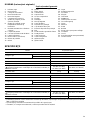
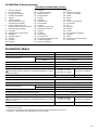
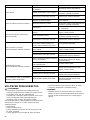
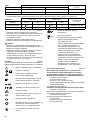
Explanation of general view
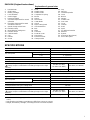
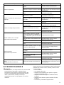
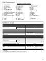
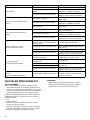
SPECIFICATIONS
• Due to our continuing program of research and development, the specifications herein are subject to change without
notice.
• Specifications and battery cartridge may differ from country to country.
• Weight, with battery cartridge, according to EPTA-Procedure 01/2003
1. Red indicator
2. Slide button
3. Battery cartridge
4. Lock-off button
5. Switch trigger
6. Reversing switch
7. A position depressed for normal
operation
8. B position depressed for weed
and debris removal
9. Speed change switch lever
10. Indication lamp
11. Most effective cutting area
12. Indicator lamps
13. CHECK button
14. Grip
15. Handle
16. Screw
17. Knob
18. Handle clamp
19. Handle holder
20. Compression spring
21. Barrier
22. Spacer
23. Arrow mark
24. Cutter blade
25. Guard
26. Nylon cutting head
27. Guard extension
28. Bolt
29. Wing
30. Two bolts
31. Protector cover
32. Hex wrench
33. Receive washer
34. Clamp washer
35. Cup
36. Hex nut
37. Threaded spindle
38. Lever
39. Buckle
40. Hanger
41. Grease hole
42. Gear case
43. Cover
44. Latches
45. Press
46. Spool
47. For left hand rotation
48. Notches
49. Eyelets
50. Protrusion (Not shown)
51. Slot of the eyelet
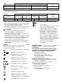
Model AT-3623/AT-3624
Type of handle Bike handle
No load speed
High 0 - 7,300 min
-1
Low 0 - 5,300 min
-1
Overall length 1,880 mm
Cutting blade diameter 230 mm
Rated voltage D.C. 36 V
Standard battery cartridge (and charger)
Always keep the combinations of battery/charger on the right
columns.
AP-363 (LG-363)/
AP-3622 (LG-3622)
AD-3612 (LG-3600 K)
Net weight 7.1 kg 12.0 kg
Model AT-3630/AT-3631
Type of handle Loop handle
No load speed
High 0 - 6,600 min
-1
Low 0 - 4,900 min
-1
Overall length 1,850 mm
Cutting diameter with nylon cutting head 300 mm
Rated voltage D.C. 36 V
Standard battery cartridge (and charger)
Always keep the combinations of battery/charger on the right
columns.
AP-363 (LG-363)/
AP-3622 (LG-3622)
AD-3612 (LG-3600 K)
Net weight 5.9 kg 10.8 kg

8
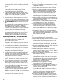
• Even if the sound pressure level listed above is 80 dB (A) or less, the level under working may exceed 80 dB (A). Wear
ear protection.
ENG901-1
• The declared vibration emission value has been
measured in accordance with the standard test method
and may be used for comparing one tool with another.
• The declared vibration emission value may also be
used in a preliminary assessment of exposure.
WARNING:
• The vibration emission during actual use of the power
tool can differ from the declared emission value
depending on the ways in which the tool is used.
• Be sure to identify safety measures to protect the
operator that are based on an estimation of exposure in
the actual conditions of use (taking account of all parts
of the operating cycle such as the times when the tool
is switched off and when it is running idle in addition to
the trigger time).
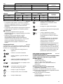
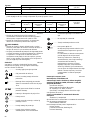
Symbols
END008-5
The following show the symbols used for the equipment.
Be sure that you understand their meaning before use.
................. Take particular care and attention.
....... Read instruction manual.
................ Danger; be aware of thrown objects.
................ The distance between the tool and
bystanders must be at least 15 m.
.......... Keep bystanders away.
....... Keep distance at least 15 m.
............... Avoid kickback.
................ Wear a helmet, goggles and ear
protection.
................. Wear protective gloves.
................ Wear sturdy boots with nonslip soles.
Steeltoed safety boots are
recommended.
................ Do not expose to moisture.
............ Top permissible tool speed.
.............Only for EU countries
Do not dispose of electric equipment or
battery pack together with household
waste material!
In observance of the European
Directives, on Waste Electric and
Electronic Equipment and Batteries
and Accumulators and Waste Batteries
and Accumulators and their
implementation in accordance with
national laws, electric equipment and
batteries and battery pack(s) that have
reached the end of their life must be
collected separately and returned to an
environmentally compatible recycling
facility.
For European countries only
ENH036-3
EC Declaration of Conformity
The undersigned, Tamiro Kishima and Rainer
Bergfeld, as authorized by Dolmar GmbH, declare that
the DOLMAR machine(s):
Designation of Machine:
Cordless Brushcutter
Model No./ Type: AT-3623, AT-3624
Specifications: see “SPECIFICATIONS” table.
are of series production and
Conforms to the following European Directives:
2000/14/EC, 2006/42/EC
And are manufactured in accordance with the following
standards or standardised documents:
EN/ISO11806, EN60745
The technical documentation is on file at:
Dolmar GmbH,
Jenfelder Straße 38, Abteilung FZ,
D-22045 Hamburg
The conformity assessment procedure required by
Directive 2000/14/EC was in Accordance with annex V.
Measured Sound Power Level: 93.6 dB (A)
Guaranteed Sound Power Level: 95 dB (A)
2. 10. 2012
Tamiro Kishima Rainer Bergfeld
Managing Director Managing Director
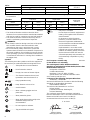
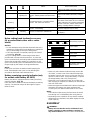
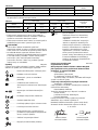
Noise Sound pressure level average
Applicable
standard
Model L
PA
(dB (A)) Uncertainty K (dB (A))
AT-3623/AT-3624 79.7 2.5 ISO22868
AT-3630/AT-3631 79.3 2.5 EN786
Vibration Left hand Right hand
Applicable
standard
Model a
h
(m/s
2
)
Uncertainty K
(m/s
2
)
a
h
(m/s
2
)
Uncertainty K
(m/s
2
)
AT-3623/AT-3624 2.5 1.5 2.5 1.5 ISO22867, EN786
AT-3630/AT-3631 2.5 1.5 2.5 1.5 EN786
Cd
Ni-MH
Li-ion

9
For European countries only
ENH043-2
EC Declaration of Conformity
The undersigned, Tamiro Kishima and Rainer
Bergfeld, as authorized by Dolmar GmbH, declare that
the DOLMAR machine(s):
Designation of Machine:
Cordless String Trimmer
Model No./ Type: AT-3630, AT-3631
Specifications: see “SPECIFICATIONS” table.
are of series production and
Conforms to the following European Directives:
2000/14/EC, 2006/42/EC
And are manufactured in accordance with the following
standards or standardised documents:
EN709, EN/ISO10517, EN/ISO11680, EN/ISO11806,
EN60745
The technical documentation is on file at:
Dolmar GmbH,
Jenfelder Straße 38, Abteilung FZ,
D-22045 Hamburg
The conformity assessment procedure required by
Directive 2000/14/EC was in Accordance with annex VIII.
Notified Body:
TÜV Rheinland LGA Products GmbH
Tillystraße 2
90431 Nürnberg, Germany
Identification number 0197
Measured Sound Power Level: 91.3 dB (A)
Guaranteed Sound Power Level: 93 dB (A)
The EC-Type Examination Certificate No. as a pole saw
with pole saw attachment is:
4811004.12011
The EC-Type Examination per 2006/42/EC was
performed by:
DEKRA Testing and Certification GmbH
Enderstraße 92b
01277 Dresden, Germany
Identification No. 2140
2. 10. 2012
Tamiro Kishima Rainer Bergfeld
Managing Director Managing Director
IMPORTANT SAFETY
INSTRUCTIONS GEB068-6
WARNING! Read all safety warnings and all
instructions. Failure to follow the warnings and
instructions may result in electric shock, fire and/or
serious injury.
Save all warnings and
instructions for future reference.
Intended use
1. The cordless grass trimmer/brushcutter/string trimmer
is only intended for cutting grass, weeds, bushes and
undergrowth. It should not be used for any other
purpose such as edging or hedge cutting as this may
cause injury.
General instructions
1. Never allow people unfamiliar with these instructions,
people (including children) with reduced physical,
sensory or mental capabilities, or lack of experience
and knowledge to use the tool. Children should be
supervised to ensure that they do not play with the
tool.
2. Before starting the tool, read this instruction manual to
become familiar with the handling of the tool.
3. Do not lend the tool to a person with insufficient
experience or knowledge regarding handling of
brushcutters and string trimmers.
4. When lending the tool, always attach this instruction
manual.
5. Handle the tool with the utmost care and attention.
6. Never use the tool after consuming alcohol or drugs,
or if feeling tired or ill.
7. Never attempt to modify the tool.
8. Follow the regulations about handling of brushcutters
and string trimmers in your country.
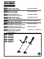
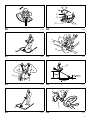
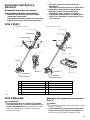
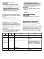
Personal protective equipment (Fig. 1)
1. Wear safety helmet, protective goggles and protective
gloves to protect yourself from flying debris or falling
objects.
2. Wear ear protection such as ear muffs to prevent
hearing loss.
3. Wear proper clothing and shoes for safe operation,
such as a work overall and sturdy, non-slip shoes. Do
not wear loose clothing or jewelry. Loose clothes,
jewelry or long hair can be caught in moving parts.
4. When touching the cutting blade, wear protective
gloves. Cutting blades can cut bare hands severely.
Work area safety
1. Operate the tool under good visibility and daylight
conditions only. Do not operate the tool in darkness or
fog.
2. Do not operate the tool in explosive atmospheres,
such as in the presence of flammable liquids, gases or
dust. The tool creates sparks which may ignite the
dust or fumes.
3. During operation, never stand on an unstable or
slippery surface or a steep slope. During the cold
season, beware of ice and snow and always ensure
secure footing.
4. During operation, keep bystanders or animals at least
15 m away from the tool. Stop the tool as soon as
someone approaches.
5. Before operation, examine the work area for stones or
other solid objects. They can be thrown or cause
dangerous kickback and result in serious injury and/or
property damage.
6. WARNING: Use of this product can create dust
containing chemicals which may cause respiratory or
other illnesses. Some examples of these chemicals
are compounds found in pesticides, insecticides,
fertilizers and herbicides. Your risk from these
exposures varies, depending on how often you do this
type of work. To reduce your exposure to these
chemicals: work in a well ventilated area, and work

10
with approved safety equipment, such as those dust
masks that are specially designed to filter out
microscopic particles.
Electrical and battery safety
1. Do not expose the tool to rain or wet conditions. Water
entering the tool will increase the risk of electric shock.
2. Do not use the tool if the switch does not turn it on and
off. Any tool that cannot be controlled with the switch
is dangerous and must be repaired.
3. Prevent unintentional starting. Ensure the switch is in
the off-position before installing a battery pack, picking
up or carrying the tool. Carrying the tool with your
finger on the switch or energising the tool that have
the switch on invites accidents.
4. Recharge only with the charger specified by the
manufacturer. A charger that is suitable for one type of
battery pack may create a risk of fire when used with
another battery pack.
5. Use the tool only with specifically designated battery
packs. Use of any other battery packs may create a
risk of injury and fire.
6. When battery pack is not in use, keep it away from
other metal objects, like paper clips, coins, keys, nails,
screws or other small metal objects, that can make a
connection from one terminal to another. Shorting the
battery terminals together may cause burns or a fire.
7. Under abusive conditions, liquid may be ejected from
the battery; avoid contact. If contact accidentally
occurs, flush with water. If liquid contacts eyes, seek
medical help. Liquid ejected from the battery may
cause irritation or burns.
Putting into operation
1. Before assembling or adjusting the tool, remove the
battery cartridge.
2. Before handling the cutter blade, wear protective
gloves.
3. Before installing the battery cartridge, inspect the tool
for damages, loose screws/nuts or improper
assembly. Sharpen blunt cutter blade. If the cutter
blade is bent or damaged, replace it. Check all control
levers and switches for easy action. Clean and dry the
handles.
4. Never attempt to switch on the tool if it is damaged or
not fully assembled. Otherwise serious injury may
result.
5. Adjust the shoulder harness and hand grip to suit the
operator’s body size.
6. When inserting a battery cartridge, keep the cutting
attachment clear of your body and other object,
including the ground. It may rotate when starting and
may cause injury or damage to the tool and/or
property.
7. Remove any adjusting key, wrench or blade cover
before turning the tool on. An accessory left attached
to a rotating part of the tool may result in personal
injury.
Operation
1. In the event of an emergency, switch off the tool
immediately.
2. If you feel any unusual condition (e.g. noise, vibration)
during operation, switch off the tool. Do not use the
tool until the cause is recognized and solved.
3. The cutting attachment continues to rotate for a short
period after turning the tool off. Don’t rush to contact
the cutting attachment.
4. During operation, use the shoulder harness. Keep the
tool on your right side firmly.
5. Do not overreach. Keep proper footing and balance at
all times. Watch for hidden obstacles such as tree
stumps, roots and ditches to avoid stumbling.
6. Never work on a ladder or tree to avoid loss of control.
7. If the tool gets heavy impact or fall, check the
condition before continuing work. Check the controls
and safety devices for malfunction. If there is any
damage or doubt, ask our authorized service center
for the inspection and repair.
8. Do not touch the gear case. The gear case becomes
hot during operation.
9. Take a rest to prevent loss of control caused by
fatigue. We recommend taking a 10 to 20-minute rest
every hour.
10. When you leave the tool, even if it is a short time,
always remove the battery cartridge. The unattended
tool with the battery cartridge installed may be used by
unauthorized person and cause serious accident.
11. If grass or branches get caught between the cutting
attachment and guard, always turn the tool off and
remove the battery cartridge before cleaning.
Otherwise the cutting attachment may rotate
unintentionally and cause serious injury.
12. If the cutting attachment hits stones or other hard
objects, immediately turn the tool off. Then remove the
battery cartridge and inspect the cutting attachment.
13. Check the cutting attachment frequently during
operation for cracks or damages. Before the
inspection, remove the battery cartridge and wait until
the cutting attachment stops completely. Replace
damaged cutting attachment immediately, even if it
has only superficial cracks.
14. Never cut above waist height.
15. Before starting the cutting operation, wait until the
cutting attachment reaches a constant speed after
turning the tool on.
16. When using metal blades, swing the tool evenly in
half-circle from right to left, like using a scythe.
17. Hold the tool by insulated gripping surfaces only,
because the cutter blade may contact hidden wiring.
Cutter blades contacting a “live” wire may make
exposed metal parts of the tool “live” and could give
the operator an electric shock.
Cutting attachments
1. Use an applicable cutting attachment for the job in
hand.
– Nylon cutting heads (string trimmer heads) are
suitable for trimming lawn grass.
– Metal blades are suitable for cutting weeds, high
grasses, bushes, shrubs, underwood, thicket, and
the like.
– Never use other blades including metal multi-piece
pivoting chains and flail blades. It may result in
serious injury.

11
2. Always use the cutting attachment guard properly
suited for the cutting attachment used.
3. When using metal blades, avoid “kickback” and
always prepare for an accidental kickback. See the
section “Kickback.”
4. When not in use, attach the blade cover onto the
blade. Remove the cover before operation.
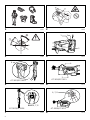
Kickback (Blade thrust)
1. Kickback (blade thrust) is a sudden reaction to a
caught or bound cutting blade. Once it occurs, the tool
is thrown sideway or toward the operator at great force
and it may cause serious injury.
2. Kickback occurs particularly when applying the blade
segment between 12 and 2 o’clock to solids, bushes
and trees with 3 cm or larger diameter. (Fig. 2)
3. To avoid kickback: (Fig. 3)
– Apply the segment between 8 and 11 o’clock.
– Never apply the segment between 12 and 2
o’clock.
– Never apply the segment between 11 and 12
o’clock and between 2 and 5 o’clock, unless the
operator is well trained and experienced and does it
at his/her own risk.
– Never use cutting blades close to solids, such as
fences, walls, tree trunks and stones.
– Never use cutting blades vertically, for such
operations as edging and trimming hedges.
Vibration
1. People with poor circulation who are exposed to
excessive vibration may experience injury to blood
vessels or the nervous system. Vibration may cause
the following symptoms to occur in the fingers, hands
or wrists: “Falling asleep” (numbness), tingling, pain,
stabbing sensation, alteration of skin color or of the
skin. If any of these symptoms occur, see a physician!
2. To reduce the risk of “white finger disease”, keep your
hands warm during operation and well maintain the
tool and accessories.
Transport
1. Before transporting the tool, turn it off and remove the
battery cartridge. Attach the cover to the cutting blade.
2. When transporting the tool, carry it in a horizontal
position by holding the shaft.
3. When transporting the tool in a vehicle, properly
secure it to avoid turnover. Otherwise damage to the
tool and other baggage may result.
Maintenance
1. Have your tool serviced by our authorized service
center, always using only genuine replacement parts.
Incorrect repair and poor maintenance can shorten the
life of the tool and increase the risk of accidents.
2. Before doing any maintenance or repair work or
cleaning the tool, always turn it off and remove the
battery cartridge.
3. Always wear protective gloves when handling the
cutting blade.
4. Always clean dust and dirt off the tool. Never use
gasoline, benzine, thinner, alcohol or the like for the
purpose. Discoloration, deformation or cracks of the
plastic components may result.
5. After each use, tighten all screws and nuts.
6. Do not attempt any maintenance or repair not
described in the instruction manual. Ask our
authorized service center for such work.
7. Always use our genuine spare parts and accessories
only. Using parts or accessories supplied by a third
party may result in the tool breakdown, property
damage and/or serious injury.
8. Request our authorized service center to inspect and
maintain the tool at regular interval.
Storage
1. Before storing the tool, perform full cleaning and
maintenance. Remove the battery cartridge. Attach
the cover to the cutting blade.
2. Store the tool in a dry and high or locked location out
of reach of children.
3. Do not prop the tool against something, such as a
wall. Otherwise it may fall suddenly and cause an
injury.
First aid
1. Always have a first-aid kit close by. Immediately
replace any item taken from the first aid kit.
2. When asking for help, give the following information:
– Place of the accident
– What happened
– Number of injured persons
– Nature of the injury
– Your name
SAVE THESE INSTRUCTIONS.
WARNING:
DO NOT let comfort or familiarity with product (gained
from repeated use) replace strict adherence to safety
rules for the subject product. MISUSE or failure to
follow the safety rules stated in this instruction
manual may cause serious personal injury.
IMPORTANT SAFETY
INSTRUCTIONS
ENC007-8
FOR BATTERY CARTRIDGE
1. Before using battery cartridge, read all
instructions and cautionary markings on (1)
battery charger, (2) battery, and (3) product using
battery.
2. Do not disassemble battery cartridge.
3. If operating time has become excessively shorter,
stop operating immediately. It may result in a risk
of overheating, possible burns and even an
explosion.
4. If electrolyte gets into your eyes, rinse them out
with clear water and seek medical attention right
away. It may result in loss of your eyesight.
5. Do not short the battery cartridge:
(1) Do not touch the terminals with any
conductive material.

12
(2) Avoid storing battery cartridge in a container
with other metal objects such as nails, coins,
etc.
(3) Do not expose battery cartridge to water or
rain.
A battery short can cause a large current flow,
overheating, possible burns and even a
breakdown.
6. Do not store the tool and battery cartridge in
locations where the temperature may reach or
exceed 50°C (122°F).
7. Do not incinerate the battery cartridge even if it is
severely damaged or is completely worn out. The
battery cartridge can explode in a fire.
8. Be careful not to drop or strike battery.
9. Do not use a damaged battery.
10. Follow your local regulations relating to disposal
of battery.
SAVE THESE INSTRUCTIONS.
Tips for maintaining maximum battery life
1. Charge the battery cartridge before completely
discharged.
Always stop tool operation and charge the battery
cartridge when you notice less tool power.
2. Never recharge a fully charged battery cartridge.
Overcharging shortens the battery service life.
3. Charge the battery cartridge with room
temperature at 10°C - 40°C (50°F - 104°F). Let a hot
battery cartridge cool down before charging it.
4. Charge the battery cartridge once in every six
months if you do not use it for a long period of
time.
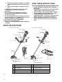
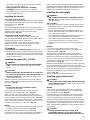
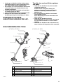
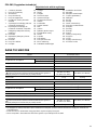
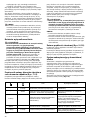
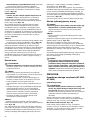
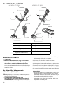
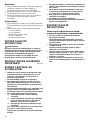
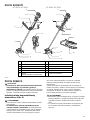
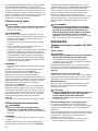
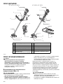
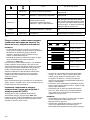
PARTS DESCRIPTIONS
013125
1 Battery cartridge 7 Gear case
2 Indication lamp 8 Cutting tool
3 Switch trigger 9 Shoulder harness
4 Hanger (suspension point) 10 Buckle
5 Grip 11 Barrier
6 Guard (cutting attachment guard) 12 Guard extension
AT-3623 / AT-3624 AT-3630 / AT-3631
1
2
3
4
5
9
7
8
1
2
6
4
6
7
8
9
10
3
5
1
1
12
10

13
FUNCTIONAL DESCRIPTION
WARNING:
• Always be sure that the tool is switched off and
battery cartridge is removed before adjusting or
checking the functions on the tool. Failure to switch
off and remove the battery cartridge may result in
serious personal injury from accidental start-up.
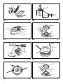
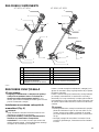
Installing or removing battery cartridge
(Fig. 4)
CAUTION:
• Always switch off the tool before installing or removing
of the battery cartridge.
• Hold the tool and the battery cartridge firmly when
installing or removing battery cartridge. Failure to
hold the tool and the battery cartridge firmly may cause
them to slip off your hands and result in damage to the
tool and battery cartridge and a personal injury.
To remove the battery cartridge, slide it from the tool while
sliding the button on the front of the cartridge.
To install the battery cartridge, align the tongue on the
battery cartridge with the groove in the housing and slip it
into place. Insert it all the way until it locks in place with a
little click. If you can see the red indicator on the upper
side of the button, it is not locked completely.
CAUTION:
• Always install the battery cartridge fully until the red
indicator cannot be seen. If not, it may accidentally fall
out of the tool, causing injury to you or someone
around you.
• Do not install the battery cartridge forcibly. If the
cartridge does not slide in easily, it is not being inserted
correctly.
Power switch action
WARNING:
• Before inserting the battery cartridge in the tool,
always check to see that the switch trigger
actuates properly and returns to the “OFF”
position when released. Do not pull the switch
trigger hard without pressing in the lock-off button.
This can cause switch breakage. Operating a tool
with a switch that does not actuate properly can lead to
loss of control and serious personal injury. (Fig. 5 & 6)
To prevent the switch trigger from being accidentally
pulled, a lock-off button is provided. To start the tool, press
in the lock-off button and pull the switch trigger. The tool
speed is increased by increasing pressure on the switch
trigger. Release the switch trigger to stop.
Reversing Switch for Debris Removal
(Fig. 7 & 8)
This tool has a reversing switch which is only provided to
change the direction of rotation so that it can be used to
remove weeds and debris entangled in the tool. To
operated the tool normally the “A” side of the switch
should be depressed.
To remove weeds and debris that are jammed in the
rotating head the tool can be reversed by depressing the
“B” side of the switch. In the reverse position the tool will
only operate for a short period of time and automatically
shut off.
WARNING:
• Always be sure that the tool is switched off and
battery cartridge is removed before removing
weeds or debris entangled in the tool that could not
be removed when operated in the reverse mode.
Failure to switch off and remove the battery cartridge
may result in serious personal injury from accidental
start-up.
NOTICE:
• Always check the direction of rotation before operation.
• Use the reversing switch only after the tool comes to a
complete stop. Changing the direction of rotation
before the tool stops may damage it.
Speed change (Fig. 9 & 10)
Two speed ranges can be preselected with the speed
change switch.
Flipping the speed change switch lever to the “1” position
will set the tool to the low speed range and the “2” position
will set the tool to the high speed range.
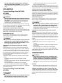
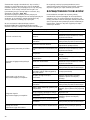
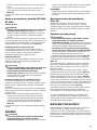
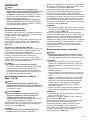
Battery/motor protection system
The battery cartridge and tool are provided with protection
devices that will automatically reduce or cut off power to
the tool when overload situations develop that may cause
damage to the tool or battery cartridge. If the tool
becomes overloaded but not locked up a protector is
provided to reduce the revolutions to protect the motor. In
this case the two indicator lamps described in the table
below do not light or blink.
All other protection functions can be identified by the
indicator lights described in the table below. (Fig. 11)

14
010823
Nylon cutting head (optional accessory
for a product that comes with a cutter
blade)
NOTICE:
• Do not attempt to bump feed the head while the tool is
operating at a high RPM. Bump feeding at a high RPM
may cause damage to the nylon cutting head.
• The bump feed will not operate properly if the head is
not rotating. (Fig. 12)
The nylon cutting head is a dual string trimmer head
provided with a bump & feed mechanism. To cause the
nylon cord to feed out, the cutting head should be bumped
against the ground while rotating at a low RPM. As the
nylon cord is feeding out it will automatically be cut to the
proper length by the cutters on the guard extension.
NOTE:
If the nylon cord does not feed out while bumping the
head, rewind/replace the nylon cord by following the
procedures described under “Maintenance.”
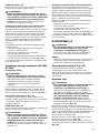
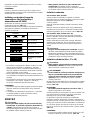
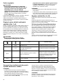
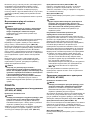
Battery remaining capacity indicator (only
for models with Battery AP-3622)
Battery AP-3622 is equipped with the battery remaining
capacity indicator. (Fig. 13)
Press the CHECK button to indicate the battery remaining
capacity. The indicator lamps will then light for approx.
three seconds.
011713
• When only the lowermost indicator lamp (next to the
“E”) blinks, or when none of the indicator lamps light,
the battery capacity has run out, so the tool does not
operate. In these cases, charge the battery or replace
the empty battery with a fully charged one.
• When two or more indicator lamps do not light even
after charging is complete, the battery has reached the
end of its service life.
• When the upper two and lower two indicator lamps light
alternately, the battery may have malfunctioned.
Contact your local Dolmar authorized service center.
NOTE:
• The indicated capacity may be lower than the actual
level during use or immediately after using the tool.
• Depending on the conditions of use and the ambient
temperature, the indication may differ slightly from the
actual capacity.
ASSEMBLY
WARNING:
• Always be sure that the tool is switched off and
battery cartridge is removed before carrying out
any work on the tool. Failure to switch off and remove
Status Action to be taken
- Blinking Battery power has been nearly used up.
Replace the battery with fully charged
one.
- Lighting On
Battery protector is shutting off the
power - battery power has been used
up.
Replace the battery with fully charged
one.
Blinking -
Overload protector is shutting off the
power - the motor was locked.
Release the switch trigger and remove
the cause of the motor lock or overload.
If the cutting tool is locked by entangling
weeds or the like, always remove the
battery cartridge before clearing it.
Lighting On -
Overheat protector is shutting off the
power - overheating.
Rest the equipment for a while.
Blinking Blinking Electric or electronic malfunction
Ask your local authorized service center
for repairs.
Indicator lamps
Remaining capacity
Lighted Off Blinking
E F
70% to 100%
45% to 70%
20% to 45%
0% to 20%
Charge the battery.
The battery may have
malfunctioned.

15
the battery cartridge may result in serious personal
injury from accidental start-up.
• Never start the tool unless it is completely
assembled. Operation of the tool in a partially
assembled state may result in serious personal injury
from accidental start-up.
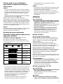
Installing the handle
For model AT-3623, AT-3624
Insert the shaft of the handle into the grip as shown. Align
the screw hole in the grip with the one in the shaft. Tighten
the screw securely. (Fig. 14)
Loosen knob.
Place handle between handle clamp and handle holder.
Adjust the handle to an angle that provides a comfortable
working position and then secure by firmly hand-
tightening knob. (Fig. 15)
For model AT-3630, AT-3631 (Fig. 16)
Fit the barrier and grip onto the shaft pipe with four
screws. Make sure that the grip/barrier assembly is fitted
between the spacer and the arrow mark.
Position the barrier on the left side of the tool. Then
tighten four screws so that the grip/barrier assembly
cannot move or rotate on the shaft pipe.
WARNING:
• Do not remove or shrink the spacer. The spacer
keeps a certain distance between both hands. Setting
the grip/barrier assembly close to the other grip beyond
the length of the spacer may cause loss of control and
serious personal injury.
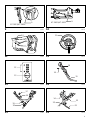
Installing the guard (Fig. 17 & 18)
WARNING:
• Never use the tool without the guard illustrated in
place. Failure to do so can cause serious personal
injury.
CAUTION:
• While installing the guard extension be careful not
to contact the sharp nylon cord cutter provided on
the guard extension. Contact with the cutter could
result in personal injury.
Attach the protector cover onto the gear case. Slightly
push the wings outward and put the bolts into the holes in
the wings. (Fig. 19)
NOTICE:
• Do not push the wings outward too much.
Otherwise it may break.
Fix the guard to the clamp with two bolts as shown.
Tighten the right and left bolts evenly. (Fig. 20)
When using a nylon cutting head, mount the guard
extension. Place the guard extension onto the mounting
track provided on the lower edge of the guard. And slide it
into position until the guard extension clicks and locks into
place. The guard extension is designed so that it will only
mount onto the guard in one direction. (Fig. 21)
NOTE:
• Remove tape adhered to cutter, which cuts nylon cord,
on guard extension at the first use. (Fig. 22)
To remove the guard extension, use a flat-blade
screwdriver and place it into the small notch provided on
the locking nub. To unlock the guard extension press
down on the locking nub while sliding the lower guard
extension in the direction indicated in the figure. Once the
guard extension starts to slide it is unlocked and can be
removed by continuing to slide it off of the guard.
Installing the cutter blade
WARNING:
• The outside diameter of the cutter blade must be
230 mm. Never use any blade exceeding 230 mm in
outside diameter.
CAUTION:
• The cutter blade must be well polished, free of cracks
or breakage. Polish or replace the cutter blade every
three hours of operation.
• Always wear gloves when handling the cutter blade.
• Always attach the blade cover when the tool is not in
use or is being transported.
• The cutter blade-fastening nut (with spring washer) is a
consumable part. If there appears any wear or
deformation on the spring washer, replace the nut. Ask
your local authorized service center to order it.
• Replace the cup in case of crack or breakage due to
attrition.
NOTICE:
• Be sure to use genuine Dolmar cutter blade.
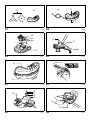
Turn the tool upside down so that you can replace the
cutter blade easily. (Fig. 23)
To dismount the cutter blade, insert the hex wrench
through the hole on the protector cover and gear case.
Rotate the receive washer until it is locked with the hex
wrench. Loosen the hex nut (left-hand thread) with the
socket wrench and remove the nut, cup, clamp washer
and hex wrench. (Fig. 24)
Mount the cutter blade onto the shaft so that the guide of
the receive washer fits in the arbor hole in the cutter
blade. Install the clamp washer, cup, and secure the cutter
blade with the hex nut with 13 to 23 Nm of tightening
torque during holding the receive washer with hex
wrench. (Fig. 25)
Make sure that the blade is the left way up.
Installing nylon cutting head
CAUTION:
• Only use the nylon cutting head with the guard and
guard extension in place. Failure to do so can cause
serious personal injury.
NOTICE:
• Be sure to use genuine Dolmar nylon cutting head.
Turn the tool upside down so that you can replace the
nylon cutting head easily. (Fig. 26)
Insert the hex wrench through the hole on the protector
cover and the gear case and rotate the receive washer
until it is locked with the hex wrench. Mount the nylon
cutting head onto the threaded spindle directly and tighten
it by turning it counterclockwise. Remove the hex wrench.
To remove the nylon cutting head, turn the nylon cutting
head clockwise while holding the receive washer with the
hex wrench.
CAUTION:
• If during operation the nylon cutting head
accidentally impacts a rock or hard object the
trimmer should be stopped and inspected for any

16
damage. If the nylon cutting head is damaged it
should be replaced immediately. Use of a damaged
nylon cutting head could result in serious personal
injury.
OPERATION
Correct handling of tool (AT-3623,
AT-3624)
Correct posture
WARNING:
• Always position the tool on your right-hand side so
that the shaft of the left handle is always in front of
your body. Correct positioning of the tool allows for
maximum control and will reduce the risk of serious
personal injury caused by kickback.
As shown in the figure fit the shoulder harness and hang
the tool firmly on your right side so that the shaft of the left
handle is always ahead of you. (Fig. 27)
Attachment of shoulder harness (Fig. 28)
Wear the shoulder harness on your back and buckle it up
until a click is heard. Make sure that it cannot be taken off
with pulling it off. Hang the tool as shown.
Detachment (Fig. 29)
The buckle is provided with a means of quick release
which can be accomplished by simply squeezing the
sides and the buckle.
WARNING:
• Be extremely careful to maintain control of the tool
at this time. Do not allow the tool to be deflected
toward you or anyone in the work vicinity. Failure to
do so could result in serious injury.
Adjustment of the hanger position and shoulder
harness
When replacing an accessory with another, the weight
balance of the tool may change. In such case, adjust the
hanger position and shoulder harness length as follows.
To change the hanger position, loosen the fixing screw on
the hanger with the supplied wrench and then move the
hanger and the cushion. The cushion can be moved
easily by twisting it.
Adjust the hanger position and shoulder harness length
so that:
- the hanger positions 750 mm or higher from the
ground,
- the cutting tool positions 100 mm to 300 mm high from
the ground and
- the unguarded part of cutting tool is horizontally
750 mm or farther away from the hanger. (Fig. 30)
After adjusting the hanger position, tighten the screw with
the wrench securely.
Correct handling of tool (AT-3630,
AT-3631)
Correct posture
WARNING:
• Always position the tool on your right-hand side so
that the barrier is always in front of your body.
Correct positioning of the tool allows for maximum
control and will reduce the risk of serious personal
injury caused by kickback.
As shown in the figure, put the shoulder harness on your
left shoulder by putting your head and right arm through it
and keep the tool on your right side while always keeping
the barrier in front of your body. (Fig. 31)
Attachment of shoulder harness (Fig. 32)
After putting the shoulder harness on it can be attached to
the tool by connecting the buckles provided on both the
tool hook and the harness. Be sure that the buckles click
and lock completely in place.
Detachment (Fig. 33)
The buckle is provided with a means of quick release
which can be accomplished by simply squeezing the
sides and the buckle.
WARNING:
• Be extremely careful to maintain control of the tool
at all times. Do not allow the tool to be deflected
toward you or anyone in the work vicinity. Failure to
keep control of the tool could result in serious injury to
the bystander and the operator.
Adjustment of the hanger position and shoulder
harness
When replacing an accessory with another, the weight
balance of the tool may change. In such case, adjust the
hanger position and shoulder harness length as follows.
To change the hanger position, loosen the fixing screw on
the hanger with the supplied wrench and then move the
hanger.
Adjust the hanger position and shoulder harness length
so that:
- the hanger positions 750 mm or higher from the
ground,
- the cutting tool positions up to 300 mm high from the
ground and
- the unguarded part of cutting tool is horizontally
750 mm or farther away from the hanger. (Fig. 34)
After adjusting the hanger position, tighten the screw with
the wrench securely.
MAINTENANCE
WARNING:
• Always be sure that the tool is switched off and
battery cartridge is removed before attempting to
perform inspection or maintenance on the tool.
Failure to switch off and remove the battery cartridge
may result in serious personal injury from accidental
start-up.
NOTICE:
• Never use gasoline, benzine, thinner, alcohol or the
like. Discoloration, deformation or cracks may result.
Supply of grease to gear case (Fig. 35)
Supply grease (Shell Alvania 2 or equivalent) to the gear
case through the grease hole every 30 hours. (Genuine
Dolmar grease may be purchased from your Dolmar
dealer.)

17
Replacing the nylon cord
WARNING:
• Always be sure that the tool is switched off and
battery cartridge is removed before attempting to
perform inspection or maintenance on the tool.
Failure to switch off and remove the battery cartridge
may result in serious personal injury from accidental
start-up.
• Make sure that the cover of the nylon cutting head
is secured to the housing properly as described
below. Failure to properly secure the cover may cause
the nylon cutting head to fly apart resulting in serious
personal injury. (Fig. 36)
Press inward on the housing latches and lift upward to
remove the cover. Discard any of the remaining nylon
cord. (Fig. 37)
Hook the middle of the new nylon cord to the notch
located at the center of the spool between the 2 channels
provided for the nylon cord. One side of the cord should
be about 80mm longer than the other side.
Wind both ends firmly around the spool in the direction
marked on the head for left hand direction indicated by
LH. (Fig. 38)
Wind all but about 100 mm of the cords, leaving the ends
temporarily hooked through a notch on the side of the
spool. (Fig. 39)
Mount the spool in the housing so that the grooves and
protrusions on the spool match up with those in the
housing. Keep the side with letters on the spool visible on
the top. Now, unhook the ends of the cord from their
temporary position and feed the cords through the eyelets
to come out of the housing. (Fig. 40)
Align the protrusion on the underside of the cover with the
slots of the eyelets. Then push cover firmly onto the
housing to secure it. Make sure the latches fully spread in
the cover.
To maintain product SAFETY and RELIABILITY, repairs,
any other maintenance or adjustment should be
performed by Dolmar Authorized Service Centers, always
using Dolmar replacement parts.
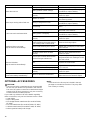
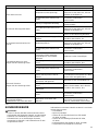
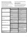
TROUBLE SHOOTING
Before asking for repairs, conduct your own inspection
first. If you find a problem that is not explained in the
manual, do not attempt to dismantle the tool. Instead, ask
Dolmar Authorized Service Centers, always using Dolmar
replacement parts for repairs.

18
010824
OPTIONAL ACCESSORIES
CAUTION:
• These accessories or attachments are recommended
for use with your Dolmar tool specified in this manual.
The use of any other accessories or attachments might
present a risk of injury to persons. Only use accessory
or attachment for its stated purpose.
If you need any assistance for more details regarding
these accessories, ask your local Dolmar Service Center.
• Cutter blade
• Nylon cutting head
• Pole hedge trimmer attachment (for model AT-3630,
AT-3631)
• Pole saw attachment (for model AT-3630, AT-3631)
• Cultivator attachment (for model AT-3630, AT-3631)
• Dolmar genuine battery and charger
NOTE:
• Some items in the list may be included in the tool
package as standard accessories. They may differ
from country to country.
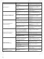
Malfunction status Cause Action
Motor does not run.
Battery cartridge is not installed. Install the battery cartridge.
Battery problem (under voltage)
Recharge the battery. If recharging is
not effective, replace battery.
The drive system does not work
correctly.
Ask your local authorized service
center for repair.
Motor stops running after a little use.
Rotation is reverse.
Change the direction of rotation with
the reversing switch.
Battery’s charge level is low.
Recharge the battery. If recharging is
not effective, replace battery.
Overheating.
Stop using of tool to allow it to cool
down.
It does not reach maximum RPM.
Battery is installed improperly.
Install the battery cartridge as
described in this manual.
Battery power is dropping.
Recharge the battery. If recharging is
not effective, replace battery.
The drive system does not work
correctly.
Ask your local authorized service
center for repair.
Cutting tool does not rotate:
stop the machine immediately!
Foreign object such as a branch is
jammed between the guard and the
nylon cutting head or cutter blade.
Remove the foreign object.
Cutter blade fastening nut is loose.
Tighten the nut properly as described
in this manual.
The cutter blade is bended. Replace the cutter blade.
The drive system does not work
correctly.
Ask your local authorized service
center for repair.
Abnormal vibration:
stop the machine immediately!
One of nylon cord has been broken
and the head got unbalanced.
Bump the nylon cutting head against
the ground while it is rotating to cause
the cord to feed.
The cutter blade is bended, cracked or
worn.
Replace the cutter blade.
Cutter blade fastening nut is loose.
Tighten the nut properly as described
in this manual.
Cutter blade is fastened improperly.
The drive system does not work
correctly.
Ask your local authorized service
center for repair.
Cutting tool and motor cannot stop:
Remove the battery immediately!
Electric or electronic malfunction.
Remove the battery and ask your local
authorized service center for repair.

19
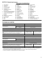
DEUTSCH (Originalanweisungen)
Erklärung der Gesamtdarstellung
TECHNISCHE DATEN
• Aufgrund unserer beständigen Forschungen und Weiterentwicklungen sind Änderungen an den hier angegebenen
Technischen Daten ohne Vorankündigung vorbehalten.
• Die Technischen Daten und der Akkublock können in den einzelnen Ländern Abweichungen aufweisen.
• Gewicht, mit Akkublock, ermittelt gemäß EPTA-Verfahren 01/2003
1. Roter Bereich
2. Schiebetaste
3. Akkublock
4. Entriegelungstaste
5. Ein/Aus-Schalter
6. Umschalter
7. A Position gedrückt für
Normalbetrieb
8. B Position gedrückt für Entfernen
von Unkraut und Ablagerungen
9. Schalter zur Änderung der
Drehzahl
10. Anzeige
11. Effektivster Schnittbereich
12. Anzeigelampen
13. Taste CHECK
14. Griff
15. Stiel
16. Schraube
17. Knauf
18. Griffklemme
19. Griffhalterung
20. Druckfeder
21. Sperre
22. Distanzstück
23. Pfeilmarkierung
24. Schneidklinge
25. Schutz
26. Nylon-Schneidkopf
27. Schutzverlängerung
28. Schraube
29. Flügel
30. Zwei Bolzen
31. Schutzabdeckung
32. Inbusschlüssel
33. Aufnahmescheibe
34. Klemmscheibe
35. Kappe
36. Sechskantmutter
37. Gewindespindel
38. Hebel
39. Gurtschloss
40. Aufhänger
41. Schmierloch
42. Getriebegehäuse
43. Abdeckung
44. Riegel
45. Drücken
46. Spule
47. Für Linke-Hand-Drehung
48. Einkerbungen
49. Seilführungen
50. Vorsprung (nicht abgebildet)
51. Schlitz der Seilführung
Modell AT-3623/AT-3624
Grifftyp Fahrradgriff
Leerlaufdrehzahl
Hoch 0 bis 7.300 min
-1
Niedrig 0 bis 5.300 min
-1
Gesamtlänge 1.880 mm
Durchmesser des Schneidblatts 230 mm
Nennspannung 36 V Gleichspannung
Standard-Akkublock (und Ladegerät)
Verwenden Sie ausschließlich die in den Spalten rechts
aufgeführten Kombinationen aus Akku und Ladegerät.
AP-363 (LG-363)/
AP-3622 (LG-3622)
AD-3612 (LG-3600 K)
Nettogewicht 7,1 kg 12,0 kg
Modell AT-3630/AT-3631
Grifftyp Bügelgriff
Leerlaufdrehzahl
Hoch 0 bis 6.600 min
-1
Niedrig 0 bis 4.900 min
-1
Gesamtlänge 1.850 mm
Schneiddurchmesser mit Nylon-Schneidkopf 300 mm
Nennspannung 36 V Gleichspannung
Standard-Akkublock (und Ladegerät)
Verwenden Sie ausschließlich die in den Spalten rechts
aufgeführten Kombinationen aus Akku und Ladegerät.
AP-363 (LG-363)/
AP-3622 (LG-3622)
AD-3612 (LG-3600 K)
Nettogewicht 5,9 kg 10,8 kg

20
• Auch wenn der oben angegebene Schalldruckpegel 80 dB (A) oder weniger beträgt, kann der Pegel beim Arbeiten
80 dB (A) übersteigen. Tragen Sie Gehörschutz!
ENG901-1
• Der hier angegebene Wert für die erzeugten
Schwingungen wurde gemäß dem genormten
Testverfahren ermittelt und kann als Vergleich zu
anderen Werkzeugen herangezogen werden.
• Der angegebene Wert für die erzeugten Schwingungen
ist außerdem für eine vorbeugende Bewertung der
Belastung zu verwenden.
WARNUNG:
• Die Schwingungsbelastung kann bei tatsächlichem
Gebrauch des Elektrowerkzeugs in Abhängigkeit von
der Handhabung des Elektrowerkzeugs von dem hier
aufgeführten Wert abweichen.
• Stellen Sie sicher, dass Schutzmaßnahmen für den
Bediener getroffen werden, die auf den unter den
tatsächlichen Arbeitsbedingungen zu erwartenden
Belastungen beruhen (beziehen Sie alle Bestandteile
des Arbeitsablaufs ein, also zusätzlich zu den
Arbeitszeiten auch Zeiten, in denen das Werkzeug
ausgeschaltet ist oder ohne Last läuft).
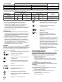
Symbole
END008-5
Im Folgenden sind die im Zusammenhang mit diesem
Werkzeug verwendeten Symbole dargestellt. Machen Sie
sich vor der Benutzung des Werkzeugs unbedingt mit
diesen Symbolen vertraut!
................. Besondere Aufmerksamkeit erforderlich!
....... Lesen Sie die vorliegende
Betriebsanleitung.
................ Gefahr; achten Sie auf umherfliegende
Gegenstände.
................ Der Abstand zwischen Werkzeug und
Umstehenden muss mindestens 15 m
betragen.
.......... Halten Sie Umstehende fern.
....... Halten Sie einen Abstand vom
mindestens 15 m ein.
............... Vermeiden Sie einen Rückschlag.
................ Tragen Sie stets Helm, Schutzbrille und
Gehörschutz.
................. Tragen Sie Schutzhandschuhe.
................Tragen Sie festes Schuhwerk mit
rutschfester Sohle. Empfohlen werden
Arbeitsschutzschuhe mit Stahlkappen.
................Setzen Sie das Werkzeug keiner
Feuchtigkeit aus.
............Maximal zulässige Drehzahl des
Werkzeugs
..........Nur für EU-Länder
Entsorgen Sie Elektrowerkzeuge,
Batterien und Akkus nicht über den
Hausmüll!
Gemäß der Europäischen Richtlinie über
Elektro- und Elektronik- Altgeräte und
über Batterien und Akkumulatoren sowie
Altbatterien und Altakkumulatoren und
ihrer Umsetzung in nationales Recht
müssen verbrauchte Elektrowerkzeuge
sowie Altbatterien und Altakkumulatoren
getrennt gesammelt und einer
umweltgerechten Wiederverwertung
zugeführt werden.
Nur für europäische Länder
ENH036-3
EG-Konformitätserklärung
Die Unterzeichnenden, Tamiro Kishima und Rainer
Bergfeld, bevollmächtigt durch die Dolmar GmbH,
erklären, dass die Geräte der Marke DOLMAR:
Bezeichnung des Geräts:
Akku-Freischneider
Nummer / Typ des Modells: AT-3623, AT-3624
Technische Daten: siehe Tabelle „TECHNISCHE
DATEN“.
in Serienfertigung hergestellt werden und
den folgenden Richtlinien der Europäischen Union
genügen:
2000/14/EG, 2006/42/EG
Außerdem werden die Geräte gemäß den folgenden
Standards oder Normen gefertigt:
EN/ISO11806, EN60745
Die technische Dokumentation befindet sich bei:
Dolmar GmbH,
Jenfelder Straße 38, Abteilung FZ,
D-22045 Hamburg
Geräuschpegel Durchschnittlicher Schalldruckpegel
Geltender
Standard
Modell L
PA
(dB (A)) Abweichung K (dB (A))
AT-3623/AT-3624 79,7 2,5 ISO22868
AT-3630/AT-3631 79,3 2,5 EN786
Schwingung Linke Hand Rechte Hand
Geltender
Standard
Modell a
h
(m/s
2
)
Abweichung K
(m/s
2
)
a
h
(m/s
2
)
Abweichung K
(m/s
2
)
AT-3623/AT-3624 2,5 1,5 2,5 1,5 ISO22867, EN786
AT-3630/AT-3631 2,5 1,5 2,5 1,5 EN786
Cd
Ni-MH
Li-ion
Strona się ładuje...
Strona się ładuje...
Strona się ładuje...
Strona się ładuje...
Strona się ładuje...
Strona się ładuje...
Strona się ładuje...
Strona się ładuje...
Strona się ładuje...
Strona się ładuje...
Strona się ładuje...
Strona się ładuje...
Strona się ładuje...
Strona się ładuje...
Strona się ładuje...
Strona się ładuje...
Strona się ładuje...
Strona się ładuje...
Strona się ładuje...
Strona się ładuje...
Strona się ładuje...
Strona się ładuje...
Strona się ładuje...
Strona się ładuje...
Strona się ładuje...
Strona się ładuje...
Strona się ładuje...
Strona się ładuje...
Strona się ładuje...
Strona się ładuje...
Strona się ładuje...
Strona się ładuje...
Strona się ładuje...
Strona się ładuje...
Strona się ładuje...
Strona się ładuje...
Strona się ładuje...
Strona się ładuje...
Strona się ładuje...
Strona się ładuje...
Strona się ładuje...
Strona się ładuje...
Strona się ładuje...
Strona się ładuje...
Strona się ładuje...
Strona się ładuje...
Strona się ładuje...
Strona się ładuje...
Strona się ładuje...
Strona się ładuje...
Strona się ładuje...
Strona się ładuje...
Strona się ładuje...
Strona się ładuje...
Strona się ładuje...
Strona się ładuje...
Strona się ładuje...
Strona się ładuje...
Strona się ładuje...
Strona się ładuje...
Strona się ładuje...
Strona się ładuje...
Strona się ładuje...
Strona się ładuje...
Strona się ładuje...
Strona się ładuje...
Strona się ładuje...
Strona się ładuje...
Strona się ładuje...
Strona się ładuje...
Strona się ładuje...
Strona się ładuje...
Strona się ładuje...
Strona się ładuje...
Strona się ładuje...
Strona się ładuje...
Strona się ładuje...
Strona się ładuje...
Strona się ładuje...
Strona się ładuje...
Strona się ładuje...
Strona się ładuje...
Strona się ładuje...
Strona się ładuje...
Strona się ładuje...
Strona się ładuje...
Strona się ładuje...
Strona się ładuje...
Strona się ładuje...
Strona się ładuje...
Strona się ładuje...
Strona się ładuje...
-
 1
1
-
 2
2
-
 3
3
-
 4
4
-
 5
5
-
 6
6
-
 7
7
-
 8
8
-
 9
9
-
 10
10
-
 11
11
-
 12
12
-
 13
13
-
 14
14
-
 15
15
-
 16
16
-
 17
17
-
 18
18
-
 19
19
-
 20
20
-
 21
21
-
 22
22
-
 23
23
-
 24
24
-
 25
25
-
 26
26
-
 27
27
-
 28
28
-
 29
29
-
 30
30
-
 31
31
-
 32
32
-
 33
33
-
 34
34
-
 35
35
-
 36
36
-
 37
37
-
 38
38
-
 39
39
-
 40
40
-
 41
41
-
 42
42
-
 43
43
-
 44
44
-
 45
45
-
 46
46
-
 47
47
-
 48
48
-
 49
49
-
 50
50
-
 51
51
-
 52
52
-
 53
53
-
 54
54
-
 55
55
-
 56
56
-
 57
57
-
 58
58
-
 59
59
-
 60
60
-
 61
61
-
 62
62
-
 63
63
-
 64
64
-
 65
65
-
 66
66
-
 67
67
-
 68
68
-
 69
69
-
 70
70
-
 71
71
-
 72
72
-
 73
73
-
 74
74
-
 75
75
-
 76
76
-
 77
77
-
 78
78
-
 79
79
-
 80
80
-
 81
81
-
 82
82
-
 83
83
-
 84
84
-
 85
85
-
 86
86
-
 87
87
-
 88
88
-
 89
89
-
 90
90
-
 91
91
-
 92
92
-
 93
93
-
 94
94
-
 95
95
-
 96
96
-
 97
97
-
 98
98
-
 99
99
-
 100
100
-
 101
101
-
 102
102
-
 103
103
-
 104
104
-
 105
105
-
 106
106
-
 107
107
-
 108
108
-
 109
109
-
 110
110
-
 111
111
-
 112
112


Dolmar AT-3624 Instrukcja obsługi
- Typ
- Instrukcja obsługi
- Niniejsza instrukcja jest również odpowiednia dla
w innych językach
- slovenčina: Dolmar AT-3624 Návod na obsluhu
- română: Dolmar AT-3624 Manualul proprietarului
Powiązane artykuły
-
Dolmar AT-3623 Instrukcja obsługi
-
-
-
-
-
-
-
-
-