Home Plow by Meyer 25000 Instrukcja obsługi
- Typ
- Instrukcja obsługi

OWNER’S MANUAL
AND
USER’S GUIDE
Read the Home Plow Owner’s Manual before operating or servicing a snow plow.
FOLLOW THESE INSTRUCTIONS EXPLICITLY.

1
Table of Contents
Subject ........................................................................................................................................................................ Page
Safety
.................................................................................................................................................................................2-3
Registration Data Sheet
..................................................................................................................................................4
Introduction
........................................................................................................................................................................4
Snow Plow Assembly
................................................................................................................................................5-11
Hook Up Plow
..................................................................................................................................................................12
Disconnect Plow
.............................................................................................................................................................13
How To Plow
.....................................................................................................................................................................14
Troubleshooting Guide
................................................................................................................................................15
Pre-season & Post-season Maintenance
..........................................................................................................16-17
Auto Angling Parts Lists
.........................................................................................................................................18-20
Power Angling Parts List
........................................................................................................................................21-23
Warranty
............................................................................................................................................................................24
Thank You
Thank you for buying the Home Plow By Meyer.
As a new owner of hard-working, mechanical
equipment, we strongly urge you to spend quality
time with this owner’s manual. It’s easy to use and
full of time-saving tips that will enhance your
ownership experience. It includes suggestions
for faster installation, safe operation and more
productive plowing.
We also strongly urge you to register your new
Home Plow at thehomeplow.com. Registering will
only take minutes and the benets of doing so
will last for years. When registered, you will receive
timely and accurate communication on operation
tips, maintenance, new products, and service
bulletins. And in the unlikely event you need
warranty work done, your local servicing dealer
will be able to process your claim faster.
Thanks again for your business. You can now look
forward to many years of reliable performance and
keeping your driveway safer and easier to use. If you
have any questions about your Home Plow, contact
us at: www.thehomeplow.com
Sincerely,
Customer Service
Home Plow by Meyer
18513 Euclid Avenue
Cleveland, Ohio 44112
800-412-PLOW (7569)

SAFETY DEFINITIONS
This is the safety alert symbol. It is used
to alert you to potential personal injury
hazards. Obey all safety messages that follow
this symbol to avoid possible injury or death.
DANGER Indicates an imminently
hazardous situation which, if not avoided,
will result in death or serious injury.
WARNING Indicates a potentially hazardous
situation which, if not avoided, could result
in death or serious injury.
CAUTION Indicates an potentially hazardous
situation which, if not avoided, may result in
minor or moderate injury.
CAUTION used without the safety alert
symbol indicates a potentially hazardous
situation which, if not avoided, will result
in property damage.
2
1
Never stand or ride on the plow assembly. Keep people and pets at least 25 feet away from the snow plow when in operation. Failure to comply
will result in death
or serious injury.
2
Insert and lock locking pin securely before using. Not doing so will result in serious injury or death. It can also result in damage to the vehicle and/or plow.
3
Always lower moldboard to the ground when snow plow is being serviced or when vehicle is not in use.
Failure to comply
could result in death or serious
injury.
4
The Home Plow is for driveway plowing only and should be used on ½-ton and smaller vehicles. Use of this product on larger than ½-ton vehicles is prohibited and can result
in damage to the vehicle or plow.
Failure to comply
could result in death or serious injury.
5
NEVER
use the Home Plow without rst CAREFULLY reading the Owner’s Manual. It is CRITICAL for your safety to ALWAYS obey EVERY warning in the manual and follow
EVERY instruction EXPLICITLY. Failure to comply
could result in death or serious injury.
6
The Home Plow by Meyer should be used by drivers with a valid operator’s license. Keep all body parts inside the vehicle.
Failure to comply
could result in death or serious injury.
7
To prevent accidental movement of the plow, always turn o the controller whenever the plow is not in use. Failure to comply
could result in death or serious injury.
8
The Home Plow should NEVER be used for ANY other purpose other than plowing snow on a driveway, using The Home Plow for other purposes could result in serious
injury or death.
9
Inspect plow assembly and mounting components and fasteners for wear and damage before and
after each use. Worn or damaged components or fasteners could
allow the plow to drop unexpectedly.
Failure to comply
could result in death or serious injury.
10
Do not change plow position while traveling. You could suddenly lower the plow accidentally. Failure to comply
could result in death or serious injury.
11
ALWAYS wear a seat belt when plowing snow. Hidden obstructions can cause the vehicle to stop suddenly resulting in personal injury. Failure to comply
could
result in death or serious injury.
12
Do not mix dierent kinds of hydraulic uid. Some uids are not compatible and may cause performance problems and product damage Failure to comply
could
result in death or serious injury.
13
NEVER perform any repairs or maintenance with the plow controller turned on and the plow plugged into the vehicle harness and the plow attached to the vehicle.
Failure to comply
could result in death or serious injury.
14
The vehicle must not be operated when overloaded. In all cases, the loaded vehicle weight, including the
entire snow plow system, all aftermarket accessories, driver, passenger,
options, nominal uid levels, and cargo
must not exceed the front/rear Gross Axle Weight Rating (GAWR), and total Gross Vehicle Weight Rating
(GVWR). These weights ratings
are specied on the safety compliance certication label on the driver’s side door opening. The use of rear ballast weight may be required to prevent exceeding the front GAWR.
Failure to comply
could result in death or serious injury.
15
Read the Home Plow Owner’s Manual before operating or servicing a snow plow. FOLLOW THESE INSTRUCTIONS EXPLICITLY. Failure to comply
could result
in death or serious injury.
16
SAFETY PRECAUTIONS should be used when Hydraulic Unit is in OPERATION and plow is in a
RAISED position. Lower plow to ground when vehicle is PARKED in case
of hydraulic failure.
Failure to comply
could result in death or serious injury.

SAFETY DEFINITIONS
This is the safety alert symbol. It is used
to alert you to potential personal injury
hazards. Obey all safety messages that follow
this symbol to avoid possible injury or death.
DANGER Indicates an imminently
hazardous situation which, if not avoided,
will result in death or serious injury.
WARNING Indicates a potentially hazardous
situation which, if not avoided, could result
in death or serious injury.
CAUTION Indicates an potentially hazardous
situation which, if not avoided, may result in
minor or moderate injury.
CAUTION used without the safety alert
symbol indicates a potentially hazardous
situation which, if not avoided, will result
in property damage.
3
17
Remove Plow Assembly before placing vehicle on hoist/lift. Failure to comply
could result in death or serious injury.
18
Do not exceed 10 mph transporting plow. Do not exceed 5 mph plowing snow. Know your road conditions at all times. Keep feet clear of moldboard at all times.
Failure to comply
could result in death or serious injury.
19
SAFETY PRECAUTIONS should be used when Hydraulic Unit is SERVICED. Hydrauilic uid under pressure can cause skin injection injury. If you are injured by
hydraulic uid, get medical attention immediately. Failure to comply
could result in death or serious injury.
20
Vehicle exhaust contains lethal fumes. Breathing these fumes, even in low concentrations, can
cause death. Never operate vehicle in an enclosed area without venting the
exhaust to the outside.
Failure to comply
could result in death or serious injury.
21
Gasoline is highly amable and gasoline vapor is explosive. Never smoke while working on vehicle. Keep all open ames away from gasoline tank and lines. Wipe up
any spilled gasoline immediately. Failure to comply
could result in death or serious injury.
22
Flag obstructions that are under snow to prevent damage to product or property. Failure to comply may result in minor or moderate injury.
23
A ballast weight may be required to prevent front GAWR overloading. If required, ballast must be securely attached at least 24 inches behind the rear axle. Failure to
comply will result in property damage.
24
Batteries normally produce explosive gases which can cause personal injury. Therefore, do not allow ames, sparks or lit tobacco to come near the battery. When charging
or working near a battery, always cover your face and protect your eyes, and also provide ventilation. Batteries contain sulfuric acid which burns skin, eyes and clothing.
Failure to comply will result in property damage.
25
See your Home Plow Authorized Distributor/Web site for specic vehicle application recommendations before installation. Failure to comply will result in property
damage.
26
Installation of a snow plow may aect your new vehicle warranty. For more information consult your Vehicle Owner’s Manual / Vehicle Dealer. Failure to comply will
result in property damage.
27
Warranty does not apply to a Home Plow product which has been negligently or improperly assembled or installed. Failure to comply will result in property damage.
28
CAUTION: To avoid harm to vehicles electrical system always disconnect battery before beginning installation. DO NOT BURN holes or WELD vehicle frame. This
may cause frame failure. Failure to comply will result in property damage.
29
A driver’s rst responsibility is the safe operation of the vehicle and snow plow. The most important thing you can do to prevent a crash is to avoid distractions and pay
attention to the road. Wait until it is safe to operate mobile communication equipment such as cell phones, two way radios, etc. Failure to comply will result in property
damage.
30
Front end wheel alignment and headlight aim may require readjustment after installation of equipment, and is the responsibility of the equipment installer. Failure
to adjust front wheel alignment may cause premature uneven tire wear. If required, reset to chassis manufacture’s specications. Failure to comply will result in
property damage.

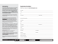
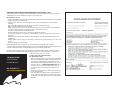
Owner Name___________________________________________________________________________________
Address______________________________________________________________________________________
City________________________________________________________________________________________
State/Province _________________________________________ Zip/Postal Code______________________________
Purchased From Company Name________________________________________________________________________
Contact Name__________________________________________________________________________________
Address______________________________________________________________________________________
City________________________________________________________________________________________
State/Province________________________________________ Zip/Postal Code______________________________
Phone Number (_________) ________________________________________________________________________
E-mail______________________________________________________________________________________
Date Purchased_________________________________________________________________________________
Vehicle Make__________________________________ Vehicle Model________________________________________
Vehicle Year___________________________________ Vehicle VIN__________________________________________
Controller Serial Number____________________________________________________________________________
Moldboard Serial number___________________________________________________________________________
Manufacturer of Hitch Mount__________________________________________________________________________
Registration Data Sheet
Register your snow plow at www.thehomeplow.com
Introduction
The Home Plow has published this manual to help you get maximum
performance from your snow plow and familiarize you with the
features designed for eciency and safety; be sure you recognize and
understand them. Follow recommended operation and maintenance
instructions, so when the storm hits, your Home Plow will be ready
and you will know how to plow like a pro. WARNING: Deployment
of an air bag while using a The Home Plow will not be covered
under The Home Plow’s warranty.
In conjunction with FMVSS (Federal Motor Vehicle Safety Standards) and
OEM (Original Equipment Manufacturer) guidelines, The Home Plow has
designed this plow pack.
We also strongly urge you to register your new Home Plow at
thehomeplow.com. Registering will only take minutes and the
benets of doing so will last for years. When registered, you will
receive timely and accurate communication on operation tips,
maintenance, new products, and service bulletins. And in the
unlikely event you need warranty work done, your local servicing
dealer will be able to process your claim faster.
Vehicle requirements: Two or Four wheel drive SUV/Pick-up type
vehicle 1/2 ton or smaller including Utility Vehicles. Use on vehicles
greater than 1/2 ton is prohibited. Minimum 60 Amp alternator.
Minimum 70 Amp Battery (550CCA/Cold Cranking Amps). Must be
able to accept a front 2” category 3 reciever hitch. Front suspension
must be able to handle 250 lbs. of added weight of plow and hitch.
Stock vehicle with no suspension modications (lift kits) that have
modied the height of the vehicle.
Hitch Requirements: Category 3 2”x2” front reciever.
300lb. Tongue weight rating – 3000lb. pull rating
THE HOME PLOW HYDRAULIC SYSTEM HAS BEEN SHIPPED DRY.
FILL ONLY WITH MEYER M-1 HYDRAULIC FLUID.
SEE PAGE 6 FOR DETAILS.
Under the continuing Home Plow Improvement Plan, The Home Plow reserves the right to
change design details and construction without prior notice and without incurring
any obligation.
4
23, 25, 26, 27
4, 6, 14
SAFETY PRECAUTIONS -
See pages 2-3 for denitions

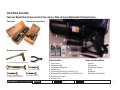
Plow Carton Hydraulic Lift Frame Carton
Snow Plow Assembly
Your new Home Plow System consist of two cartons, Plow Carton and Hydraulic Lift Frame Carton.
1
2
6
4
3
5
Carton contains:
1. Plow Assembly
2. Hydraulic Assembly
3. Auto or Power Angling Ram
4. Hydraulic Cover
5. Plow Parts Bag (08258 pg. 18 or 08263 pg. 21)
6. Mounting Hardware Bag (08245 pg. 18 or 08264 pg. 21)
7. Hydraulic Fluid (2 quarts)
8. Dielectric Grease
Items not shown above:
Controller
Vehicle Harness
Vehicle Harness Extension
Zip Ties
Plow Marker
Hitch Mount (sold separately)
Recommended assembly tools:
1/2” drive ratchet with 15/16” deep well socket
15/16” combination wrench
side cutters
1/2” combination wrench
8 or 10mm combination wrench
dependant on vehicle manufacturer
12mm combination wrench
5
7
8
27, 28
12
SAFETY PRECAUTIONS -
See pages 2-3 for denitions

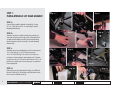
STEP 1a
Connect Plow Assembly to Hydraulic Assembly (g. 1) using
5/8-11 x 5” Bolt (g. 2) and 5/8-11 Locknut (g. 3) from the
Mounting Hardware Bag.
STEP 1b
Attach the two wheel assemblies with the shorter brackets to
either side of the plow pivot bar (g. 4 & 5) and the third wheel
assembly to the Hydraulic Assembly A-frame under the lifting
cylinder using three Hair Pin Cotter (g. 6) from the Mounting
Hardware Bag.
STEP 1c
Attach the Auto or Power Angling Ram to the A-Frame using two
1/2 x 3” Pivot Pins (g. 7), six 1/2” Flatwashers and two
1/8” x 1-5/16” Hair Pins (g. 8). Be sure four 1/2” washers are
positioned as shown in gure 8 and remaining two 1/2” washers
are placed over the 1/2” x 3” Pivot Pins before the two 1/8” 1-5/16”
Hair Pins are installed. Figure 9 shows the proper set-up with the
Power Angling Ram.
STEP 1d
Remove Reservoir Cap from Hydraulic unit (g. 10) and ll with
Meyer M-1 Fluid (g. 11) Provided up to the full mark located on
the reservoir. Re-install Reservoir Cap.
STEP 1:
PLOW & HYDRAULIC LIFT FRAME ASSEMBLY
(Fig. 1) (Fig. 2) (Fig. 3)
(Fig. 4) (Fig. 5) (Fig. 6)
(Fig. 7) (Fig. 8)
(Fig. 9)
(Fig. 10)
(Fig. 11)
6
9, 12
SAFETY PRECAUTIONS -
See pages 2-3 for denitions

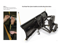
Your Home Plow System should now look like the picture below.
7
STEP 1e
Install Plow Markers to each side of plow using
5/16-18 x 1” bolt, 5/16 atwashers and 5/16-18
locknut as shown below.

STEP 2a
Carefully route the Vehicle Harness to the vehicle battery (g. 12). You may
need to route thru the grille or behind/under the bumper. Be sure to stay
away from hot, sharp or moving parts of the vehicle and use the zip ties
provided to secure. Attach the Black wire to the negative (-) battery post
(g. 13) and the red wire to the positive (+) battery post (g. 14).
STEP 2b
Carefully attach the Vehicle Harness Extension to the vehicle harness
(g. 15) and route extension into the vehicle. The extension can either
be routed thru the rewall (g. 16) or along the hood channel (g. 17)
and thru the window or door jamb (g. 18). Be sure to stay away from
hot, sharp or moving parts of the vehicle and use the zip ties provided
to secure. If routing thru window or door make sure the hood,
door or window closes without pinching or cutting the harness.
Connect the Controller to the Harness Extension (g. 19).
STEP 2c
Install your Receiver Hitch Mount (sold separately, see hitch
requirements on pg. 4) per manufacturers instructions. Measure
center of square hitch to the ground. This dimension (A) should be a
minimum of 11” and a maximum of 14” (g. 20). Measure from the
hitch pin hole to the very end of your bumper. This dimension (B)
should be not more than 8-1/2” (g. 20). If your dimension does
not fall within these ranges you should contact your hitch dealer/
manufacturer for height or length adjustment accessories.
(A) 11” min-14” max
(B)
8-1/2” max
STEP 2:
WIRING INSTALLATION
(Fig. 20)
(Fig. 12)
8
(Fig. 13)
(Fig. 14)
(Fig. 15) (Fig. 16)
(Fig. 17)
(Fig. 18)
(Fig. 19)
24, 25, 26, 27, 28
9, 20, 21
SAFETY PRECAUTIONS -
See pages 2-3 for denitions

Remove Pin
Lift here and push toward vehicle.
STEP 3: INSTALL PLOW ONTO VEHICLE
Lift here
STEP 3a
Gently roll the plow to the receiver hitch on the vehicle so that the male tube on the
lift frame is lined up directly in front of the receiver hitch (g. 21). Lift slightly on the
“Lift Here” decal (g. 22) and push plow assembly into the vehicle receiver hitch until
the pin holes align (g. 23). Proper install is shown in Figure 24.
(Fig. 21)
(Fig. 22)
(Fig. 23)
(Fig. 24)
9
2
9
SAFETY PRECAUTIONS -
See pages 2-3 for denitions

STEP 3b
Remove both weather covers from the
ends of the Plow Harness and Vehicle
Harness, add dielectric grease to the
connecting prongs and connect.
STEP 3c
Turn on Controller.
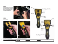
Auto Angling Controller (Part #22826) Power Angling Controller (Part #22827)
On
O
Raise
(UP)
Lower
(DOWN)
On/O
Raise
(UP)
Lower
(DOWN)
Angle
Left
Angle
Right
10
Auto Angling Controller
(Part #22826)
Power Angling Controller
(Part #22827)
28
7
SAFETY PRECAUTIONS -
See pages 2-3 for denitions

STEP 3d
Raise plow and reposition the two front wheel brackets 180 degrees (g. 25) and the one rear wheel bracket
90 degrees (g. 26) for plowing mode.
STEP 3e
Raise and lower (and angle left & right if equipped with power angling) plow 10 times to automatically
purge the air out of the hydraulic system. Lower plow to ground and turn o controller. Check uid level in
hydraulic unit (g. 27) and top o if necessary (g. 28)(see step 1d). Attach Hydraulic Cover to Hydraulic
Assembly Lift Frame using two Cover fasteners on each side (g. 29). (The cover fasteners are locked in place
when the center nail of the cover fastener is pushed in)
Auto Angling Controller Operation
(Part #22826): Turn the controller on. When turned on the controller
will illuminate. The Plow UP and Plow DOWN switch is a 3 position switch. The
plow can be raised “up” by pressing on the top half of the Plow Up/Plow Down
switch. Once released, the switch will return to the center position. The plow can
be lowered by pressing the bottom half of the Plow Up/Plow Down switch. This
will stay in the Down or “Float” position until the operator pushes the switch to
the center position or raise “Plow UP” position. When the switch is in the Down
or “Float” position it will keep the S1 valve energized which will allow the plow
to remain in contact with the ground regardless of grade. When the switch is
in the center position it will not allow the plow to lower automatically when
encountering a dierent grade. Make sure controller is turned o when plow is
not in use.
Power Angling Controller Operation
(Part #22827):
Turn the controller on by holding down the on/o
switch until the controller lights up (1 second). To raise the plow press the up
arrow. To angle the plow left press the left arrow and to angle the plow right
press the right arrow. The plow can be lowered by pressing the lower (down)
arrow. If the lower button is pressed for more than 1 second the plow will go
into “Float”. “Float” position will keep the S1 valve energized which will allow the
plow to remain in contact with the ground regardless of grade. Pressing the raise
arrow will take the plow out of Float and will not allow the plow to lower
automatically when encountering a dierent grade. The controller has timers
built in for safety. The plow will only raise continually for 4 seconds at a time
and angle left or right continually for 6 seconds at a time. The controller will
automatically shut down the function being used if the timer values (4 seconds
for raise and 6 seconds for angle) are exceeded. In order to reset simply release
the function being pressed and this will reset the timer and controller.
Make sure controller is turned o when plow is not in use.
11
(Fig. 25)
(Fig. 26)
(Fig. 27)
(Fig. 28)
(Fig. 29)
1
24
7, 12, 16, 19, 20, 21
SAFETY PRECAUTIONS -
See pages 2-3 for denitions

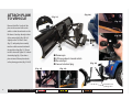
ATTACH PLOW
TO VEHICLE
Remove Hitch Pin. Gently roll the
plow to the receiver hitch on the
vehicle so that the male tube on the
lift frame is lined up directly in front
of the receiver hitch (g. 30). Lift
slightly on the “Lift Here” decal
(g. 31) and push plow assembly
into the vehicle receiver hitch until
the pin holes align (g. 32). Proper
install is shown in Figure 34. Connect
electrical plug (g. 33) and raise
plow to turn all three plow wheels
to the plowing position (g 35 & 36).
Plow wheels set to
plowing position.
12
Remove pin
Lift here and push toward vehicle
Re-install pin
Connect electrical plug
(Fig. 31)
(Fig. 30)
(Fig. 32)
(Fig. 33)
(Fig. 34)
(Fig. 35) (Fig. 36)
2
30
7, 9
SAFETY PRECAUTIONS -
See pages 2-3 for denitions

(Fig. 37)
(Fig. 38)
(Fig. 39)
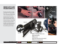
REMOVE PLOW
FROM VEHICLE
Raise plow and set wheels to storage
position (g. 37-39). Lower plow into
“Float” position and push down on lift
arm to put slack into the lift chain
(g. 40). Disconnect electrical plug
(g. 41) and install weather covers to
both end of the harness. Remove Hitch
pin (g. 40). Gently lift at “Lift Here”
decal (g. 42) and slide Lift Frame out
of reciever hitch on vehicle (g. 43).
Re-install Hitch pin thru Lift Frame.
Push here to put slack in chain
Disconnect plug
Remove pin
Lift here and pull away from vehicle
Replace pin to plow hitch
(Fig. 40)
(Fig. 41)
(Fig. 42)
(Fig. 43)
13
7
SAFETY PRECAUTIONS -
See pages 2-3 for denitions

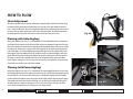
Chain Adjustment
The chain is adjustable at the lift arm. The chain must be adjusted with the controller in the down (Float)
position and the lift cylinder must be pushed down as far as it will go. The chain should be adjusted to
have 2-3 links of slack (g.44). Also if a major hydraulic malfunction is experienced the plow can be raised
by a oor jack or two people and the chain can be adjusted up with no slack. This will then suspend the
plow above ground so the vehicle can be driven to your nearest Home Plow Service center.
Plowing (with Auto Angling)
Always plow with the storm, every 2-3” of accumulation. The Auto Angling Plow will raise and lower the
plow from inside the comfort of your vehicle and allows the plow to automatically angle to the side with
the heaviest amount of snow and when raised the plow will automatically return to the center or straight
position (g. 45). The plow also is equipped with a xed angle pin (g. 46) which can position the plow
to the left or right. To use the xed angle pin manually push the plow to the left or right and drop in the
xed angle pin and secure with the hair pin. Lift as high as possible, then drive through the snow to the
garage. Drop the blade and back drag away from the garage. Turn around, back into the cleared path to
the garage, set the blade in an angled position if necessary and continue rolling snow away from the
house. Complete as many passes as necessary to clear the snow. The rst storm of the season, plow back
from the drive area to allow space to pile future snowfall.
Plowing (with Power Angling)
Always plow with the storm, every 2-3” of accumulation. The Power Angling Plow will raise, lower, angle
left and angle right from inside the comfort of your vehicle (g. 47). Enter the driveway rolling snow away
from the residence. Stop about two-thirds of the way in, set the blade in angled position, lift as high as
possible, then drive through the snow to the garage. Drop the blade and back drag away from the garage.
Turn around, back into the cleared path to the garage, reset the blade angle and continue rolling snow
away from the house. Complete as many passes as necessary to clear the snow. The rst storm of the
season, plow back from the drive area to allow space to pile future snowfall.
(Fig. 46)
(Fig. 45)
HOW TO PLOW
(Fig. 47)
14
(Fig. 44)
1, 2
23, 24, 29, 30
3, 4, 5, 6, 7, 8, 9, 10, 11, 14, 16, 18, 19, 20, 21
SAFETY PRECAUTIONS -
See pages 2-3 for denitions

CONDITION POSSIBLE CAUSE CORRECTION
Plow
doesn’t
lift 1. Low hydraulic uid level. 1. Add uid to proper level
or lifts slowly – 2. Discharged battery. 2. Recharge battery.
motor operates 3. Leaking or open “S1” cartridge. 3. Clean or replace “S1” cartridge.
4. Malfunctioning Hydraulic Unit. 4. Replace Hydraulic Unit.
Motor doesn’t
1. No current to Motor Solenoid 1. Locate malfunction and repair.
operate
(small red wire)
(Check controller)
2. Small purple wire not grounded 2. Ground small purple wire
3. Malfuctioning Motor Solenoid 3. Replace motor Solenoid
4. Malfunctioning motor 4. Replace motor
5. Malfunctioning Hydraulic Unit 5. Replace Hydraulic Unit
Plow
doesn’t
1. No current to “S1” coil. 1. Locate malfunction and repair.
lower
(white and black with white stripe wires) (Check controller)
2. “S1” cartridge jammed in closed position.
2. Replace “S1” cartridge.
3. Inoperative “S1” coil. 3. Replace “S1” coil.
(black with white stripe & white wire) (black with white stripe & white wire)
Plow creeps down
1. Leaking “S1” cartridge. 1. Clean or replace “S1” cartridge.
2. Leaking Raise Cylinder. 2. Replace Raise Cylinder.
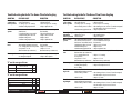
Troubleshooting Guide for The Home Plow Auto Angling
CONDITION POSSIBLE CAUSE CORRECTION
Plow does not lift 1. Low hydraulic uid level. 1. Add uid to proper level
or lifts slowly – 2. Discharged battery. 2. Recharge battery.
motor operates
3. Leaking or open “S1” cartridge. 3. Clean or replace “S1” cartridge.
4. Motor turning counter clockwise
4. Check wiring to motor solenoid
(T1 should be energized)
– Check Controller – Replace motor solenoid.
5. Malfunctioning Hydraulic Unit. 5. Replace Hydraulic Unit.
Plow Angles Right
1. Leaking or open “S2” cartridge. 1. Clean or replace “S2” cartridge.
when Raise 2. Wiring not correct 2. Check wiring harness
switch is pressed 3. Bad Controller 3. Replace Controller
Motor
doesn’t
1. Check red and black wires at battery
.
1. Clean and tighten connection
operate 2. No current to Motor Solenoid. 2. Locate malfunction and repair.
(small red wire T1 & small black wire T2) (Check controller)
3. Malfuctioning Motor Solenoid 3. Replace motor Solenoid
4. Malfunctioning motor. 4. Replace motor.
5. Malfunctioning Hydraulic Unit. 5. Replace Hydraulic Unit.
Plow doesn’t
1. No current to “S1” coil. 1. Locate malfunction and repair.
(Check controller)
lower
(black with white stripe & white wire)
2. “S1” cartridge jammed in 2. Replace “S1” cartridge.
closed position.
3. Inoperative “S1” coil. 3. Replace “S1” coil.
(black with white stripe & white wire) (black with white stripe & white wire)
Plow creeps down
1. Leaking “S1” cartridge. 1. Clean or replace “S1” cartridge.
2. Leaking Raise Cylinder, 2. Replace Raise Cylinder or hose.
hose or tting.
Plow does not 1. No current to “S2” coil.
1. Locate malfunction and repair.
(orange & black w/white stripe wire)
angle Left
(orange and black w/white stripe wire)
2. Motor tuning clockwise. 2. Check wiring of motor solenoid.
(T2 should be energized)
– Check Controller – Replace motor solenoid.
3. Bad”S2” valve. 3. Replace “S2” valve.
Plow does not 1. No current to “S2” coil.
1. Locate malfunction and repair.
(orange & black w/white stripe wire)
angle Right
(orange and black w/white stripe wire)
2. Motor tuning counter clockwise. 2. Check wiring of motor solenoid.
(T1 should be energized)
– Check Controller – Replace motor solenoid.
3. Bad”S2” valve. 3. Replace “S2” valve.
Motor Solenoid S1
Raise X
Lower X
Motor Solenoid S1 S2
Raise X (T1)
Lower X
Left X (T2) X
Right X (T1) X
“X” are the energized items.
“X” are the energized items.
15
Troubleshooting Guide for The Home Plow Power Angling
24
7, 12, 13, 15, 16, 17, 19, 20, 21
SAFETY PRECAUTIONS -
See pages 2-3 for denitions

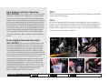
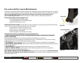
The Home Plow recommends this maintenance information for regular service. Sustained heavy operation may call for more frequent service. Snow plowing
subjects a vehicle to exceptionally rugged use. As a result, it is very important to inspect and maintain the snow plow and vehicle up to maximum operating conditions.
Inspection should be made of both the vehicle and snow plow prior to the plowing season and after each use.
PRESEASON MAINTENANCE Scheduled vehicle maintenance should be performed as recommended by the manufacturer.
Don’t forget that in addition to keeping equipment in order:
1. Keep windshield wipers, heaters and lights working.
2. Use emergency asher lights for increased visibility and safety.
3. Equip vehicles with chains where necessary.
VEHICLE ELECTRICAL SYSTEM For maximum eciency, the vehicle supporting the snow plow must be properly serviced. The system should
consist of at least a 70 amp./hr. battery and a 60 amp alternator. Be sure to check regularly:
1. Battery terminals to assure they’re clean and free of corrosion.
2. Electrical connections, to assure they’re tight and corrosion free.
3. Battery must be in top operating condition.
4. Alternator and regulator, to assure maximum electrical output.
Check the Diagnosis chart Pre/Post Season Maintenance for advice on maintaining the unit.
1.
ALWAYS LOWER MOLDBOARD TO THE GROUND WHEN SNOW PLOW IS BEING SERVICED OR WHEN
VEHICLE IS NOT IN USE
.
2. Check and maintain hydraulic uid reservoir level to Full. Oil level should be checked with lift ram down or retracted position.
3. Check entire hydraulic system for leaks. A signicant drop in hydraulic uid level is evidence of a leak which must be corrected to prevent serious damage.
4. Before and after each season, Grease all pins and lubricate all pivot points with chassis lube.
5. CUTTING EDGE – Replace the cutting edge as soon as it is 3-1/2” (5” is new) Tall. This will prevent permanent damage to the moldboard (g. 48).
6. ADJUSTING TRIP SPRING TENSION – Tighten top locknut 4 turns beyond the point when spring coils begin to separate. Tighten bottom locknut to
hold eye bolt in position (g. 49).
7. MOUNTING BOLTS – Retighten all mounting bolts after rst snow plowing session and at regular intervals through the season.
8. SNO-FLO® POWDER COATING, both black and yellow, should be checked at the beginning and end of each season for any signs of rust.
If any exists, use Sno-Flo® powder coat touch-up available in spray cans.
NOTE: PROTECTION AGAINST RUST AND CORROSION When the power unit is not used for extended periods, protect the chromed
lift rod by fully extending and coating it with chassis lubricant. Coat the exposed portions of the power angling cylinder rods with chassis
lubricant to protect against corrosion.
Pre-season & Post-season Maintenance
Trip Spring Adjustment
Cutting Edge
(Fig. 48)
(Fig. 49)
16
24, 30
4, 7, 9, 12, 13, 15, 16, 17, 19, 20, 21
SAFETY PRECAUTIONS -
See pages 2-3 for denitions

Grease
Grease
Grease
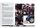
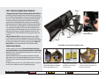
POSTSEASON SUMMER MAINTENANCE
1. Draining & Replacing The Home Plow Meyer M-1 Hydraulic Fluid Drain
the uid by un-bolting the hydraulic unit from the Lift Frame and removing the
Reservoir Breather. Turn the hydraulic unit upside down and drain the uid from
the reservoir. To drain the uid from the power angling cylinders(if equipped),
disconnect the ttings and completely retract the cylinder rods and purge
cylinder and hose of all hydraulic uid. The complete system should then be
ushed out with Meyer M-2 Flushing Fluid before adding new Meyer Hydraulic
Fluid. To ush the unit, re-install the hydraulic unit to the Lift Frame and hose
to the angle cylinder (if equipped). Add 1 quart of M-2 Flushing Fluid to the
reservoir and replace the Reservoir Breather. Cycle the unit Up, Down, Left and
Right 5 times in each direction. Then drain the hydraulic unit as before and
re-ll with Meyer M-1 Fluid. Check uid level after cycling plow and top o if
necessary.
2. Meyer M-1 Hydraulic Fluid is specially formulated with an anti-ice additive
for almost constant viscosity in subzero temperatures. Because it is free-owing in
extreme cold, the unit’s performance and eciency are not aected by winter weather.
It is eective for a maximum of one year. Always carry an extra quart of Meyer M-1
Hydraulic Fluid. Use of any inferior uids will void The Home Plow warranty.
SNOW PLOW STORAGE
1. When snow plow is disconnected, disconnect lift chain from lift arm
and extend lift cylinder to end of stroke and coat chrome rod with light
grease. This lls the cylinder with hydraulic uid and protects the interior and
exterior from rust and corrosion.
2. Whenever Moldboard is disconnected, coat the exposed portions of the power
angling cylinder chrome rod (if equipped) with light grease to protect it from corrosion.
3. Coat pivot pin and other wear points with chassis lubricant. Be sure to grease all
grease holes.
4. Unplug electical connection. Coat connection with a dielectric compound to
prevent corrosion and plug into their corresponding weather plug.
Yellow and black paint is formulated
to withstand harsh temperatures and
the winter environment.
Protects your electrical system
with Meyer winter formula
dielectric grease.
Meyer M1 Hydraulic oil and Flush is
scientically formulated to withstand
extreme winter temps up to -40F.
Dielectric Grease
Available at www.thehomeplow.com
17
24, 30
7, 9, 12, 13, 15, 16, 17, 19, 20, 21
SAFETY PRECAUTIONS -
See pages 2-3 for denitions

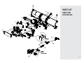
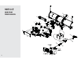
Parts indented are included in the assembly under which
they are indented.
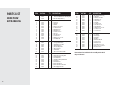
PARTS LIST
HOME PLOW
AUTO ANGLING
ITEM PART NO. QTY. DESCRIPTION
25000 Home Plow Auto Angling
t )PNF1MPX1"'-JGU'SBNF"VUP"OHMJOH
tt-JGU'SBNF)ZESBVMJD"TTZ
ttt"'SBNF
ttt3FBS$PWFS
ttt-JGU'SBNF
ttt-JGU"SN
ttt#PMUYw(S
ttt-PDLXBTIFSw
ttt'MBUXBTIFSw
ttt'MBUXBTIFSw
ttt$PUUFS1JOwYw
ttt1JOwYw
ttt1JWPU1JOwYw
ttt$PWFS'BTUFOFS
ttt)BJS1JOwYw
ttt1MPX.BSLFS,JU
ttt"VUP"OHMJOH)ZESBVMJD6OJU"TTZ
ttttEFHSFF&MCPX4"&
tttt-JGU$ZMJOEFSwYw4"&
tttt1MPX4JEF)BSOFTT
tttt)PTF"TTFNCMZ4"&
tttt.PUPS4PMFOPJE
tttt1PXFS$BCMF
tttt.PUPS4PMFOPJE(SPVOE8JSF
tt1MPX1BSUT$BSUPO
ttt%VBM$PNQSFTTJPO4QSJOH3BN
ttt$BSU1JWPU#SBDLFU
ttt$BSU+BDL#SBDLFU
ttt2VBSU.FZFS.)ZESBVMJD'MVJE
ttt'SPOU$PWFS
ttt1MPX$BSU$BTUFS
ttt7FIJDMF4JEF)BSOFTT
ttt7FIJDMF4JEF)BSOFTT&YUFOTJPO
ttt"VUP"OHMJOH$POUSPMMFS
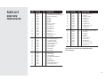
ITEM PART NO. QTY. DESCRIPTION
ttt.PVOUJOH)BSEXBSF#BH
tttt)JOHF1JO
tttt#PMUYw(S
tttt'MBUXBTIFSw
tttt)BJSQJO$PUUFS
tttt-ZODI1JO
tttt-PDLOVU
tttt1JWPU1JOwYw
tttt'JYFE"OHMF1JO
tttt)BJS1JOwYw
tttt-PDLOVU
tttt$PWFS'BTUFOFS
tt)1w.PMECPBSE1JWPU"TTFNCMZ
ttt&ZF#PMU,JU
ttt$VUUJOH&EHF
ttt5SJQ4QSJOH
ttt1JWPU#BS
ttt)1w.PMECPBSE
ttt-PDLOVU
ttt'MBUXBTIFSw
ttt$PUUFS1JOwYw
ttt#PMUYw(S
ttt1JWPU1JOYw
18

17
1
3
4
15
5
6
7
13
9
19
10
16
11
23
32
33
34
40
35
36
37
38
39
41
35
42
2
24
25
27
28
43
44
45
46
47
48
49
50
51
52
8
8
13
13
16
11
11
34
40
38
41
35
12
28
45
8
34
14
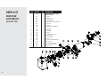
PARTS LIST
HOME PLOW
AUTO ANGLING
19
Strona się ładuje...
Strona się ładuje...
Strona się ładuje...
Strona się ładuje...
Strona się ładuje...
-
 1
1
-
 2
2
-
 3
3
-
 4
4
-
 5
5
-
 6
6
-
 7
7
-
 8
8
-
 9
9
-
 10
10
-
 11
11
-
 12
12
-
 13
13
-
 14
14
-
 15
15
-
 16
16
-
 17
17
-
 18
18
-
 19
19
-
 20
20
-
 21
21
-
 22
22
-
 23
23
-
 24
24
-
 25
25


Home Plow by Meyer 25000 Instrukcja obsługi
- Typ
- Instrukcja obsługi
w innych językach
- English: Home Plow by Meyer 25000 User manual
Inne dokumenty
-
MURPHY DOOR 1689351746 Instrukcja obsługi
-
LG 49LH541V Instrukcja obsługi
-
DK2 Rampage II Instrukcja obsługi
-
Fab Glass and Mirror BC155 Instrukcja obsługi
-
Southern Living Plant Collection 51693 Specyfikacja
-
Sea Ray 2005 270SLX Parts Manual
-
Lifetime 1558 Instrukcja obsługi
-
AMP Research 75132-01A Instrukcja instalacji
-
-