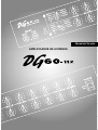
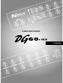
Yamaha DG60 Instrukcja obsługi
- Kategoria
- Instrumenty muzyczne
- Typ
- Instrukcja obsługi
Niniejsza instrukcja jest również odpowiednia dla

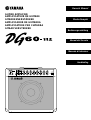
Owner’s Manual
Mode d’emploi
Bedienungsanleitung
GUITAR AMPLIFIER
AMPLIFICATEUR DE GUITARE
GITARRENVERSTÄRKER
AMPLIFICADOR DE GUITARRA
AMPLIFICATORE PER CHITARRA
GITAAR VERSTERKER
Manuale di Istruzioni
Manual del Usuario
Handleiding

2
• This applies only to products distributed by Yamaha-Kemble Music (U.K.) Ltd.
IMPORTANT NOTICE FOR THE UNITED KINGDOM
Connecting the Plug and Cord
WARNING: THIS APPARATUS MUST BE EARTHED
IMPORTANT. The wires in this mains lead are coloured in
accordance with the following code:
GREEN-AND-YELLOW : EARTH
BLUE : NEUTRAL
BROWN : LIVE
As the colours of the wires in the mains lead of this apparatus may not
correspond with the coloured markings identifying the terminals in your
plug proceed as follows:
The wire which is coloured GREEN-and-YELLOW must be connected
to the terminal in the plug which is marked by the letter E or by the
safety earth symbol or colored GREEN or GREEN-and-YELLOW.
The wire which is coloured BLUE must be connected to the terminal
which is marked with the letter N or coloured BLACK.
The wire which is coloured BROWN must be connected to the terminal
which is marked with the letter L or coloured RED.
FCC INFORMATION (U.S.A.)
1. IMPORTANT NOTICE: DO NOT MODIFY THIS UNIT!
This product, when installed as indicated in the instructions
contained in this manual, meets FCC requirements. Modifica-
tions not expressly approved by Yamaha may void your au-
thority, granted by the FCC, to use the product.
2. IMPORTANT: When connecting this product to accessories
and/or another product use only high quality shielded cables.
Cable/s supplied with this product MUST be used. Follow all
installation instructions. Failure to follow instructions could
void your FCC authorization to use this product in the USA.
3. NOTE: This product has been tested and found to comply
with the requirements listed in FCC Regulations, Part 15 for
Class “B” digital devices. Compliance with these require-
ments provides a reasonable level of assurance that your use
of this product in a residential environment will not result in
harmful interference with other electronic devices. This
equipment generates/uses radio frequencies and, if not in-
stalled and used according to the instructions found in the
users manual, may cause interference harmful to the opera-
tion of other electronic devices. Compliance with FCC regula-
tions does not guarantee that interference will not occur in all
installations. If this product is found to be the source of inter-
ference, which can be determined by turning the unit “OFF”
and “ON”, please try to eliminate the problem by using one of
the following measures:
Relocate either this product or the device that is being af-
fected by the interference.
Utilize power outlets that are on different branch (circuit
breaker or fuse) circuits or install AC line filter/s.
In the case of radio or TV interference, relocate/reorient the
antenna. If the antenna lead-in is 300 ohm ribbon lead,
change the lead-in to co-axial type cable.
If these corrective measures do not produce satisfactory
results, please contact the local retailer authorized to distrib-
ute this type of product. If you can not locate the appropriate
retailer, please contact Yamaha Corporation of America,
Electronic Service Division, 6600 Orangethorpe Ave, Buena
Park, CA90620
The above statements apply ONLY to those products distrib-
uted by Yamaha Corporation of America or its subsidiaries.
* This applies only to products distributed by YAMAHA CORPORATION OF AMERICA.
The exclamation point within the equilateral
triangle is intended to alert the user to the
presence of important operating and mainte-
nance (servicing) instructions in the literature
accompanying the product.
The lightning flash with arrowhead symbol,
within the equilateral triangle, is intended to
alert the user to the presence of uninsulated
“dangerous voltage” within the product’s
enclosure that may be of sufficient magnitude
to constitute a risk of electrical shock.

3
WARNING- When using any electrical or electronic product,
basic precautions should always be followed. These precautions
include, but are not limited to, the following:
1. Read all Safety Instructions, Installation Instructions,
Special Message Section items, and any Assembly Instructions
found in this manual BEFORE making any connections, including
connection to the main supply.
2. Do not attempt to service this product beyond that de-
scribed in the user-maintenance instructions. All other servicing
should be referred to qualified service personnel.
3. Main Power Supply Verification: Yamaha products are
manufactured specifically for the supply voltage in the area where
they are to be sold. If you should move, or if any doubt exists
about the supply voltage in your area, please contact your dealer
for supply voltage verification and (if applicable) instructions. The
required supply voltage is printed on the name plate. For name
plate location, please refer to the graphic found in the Special
Message Section of this manual.
4. DANGER-Grounding Instructions: This product must be
grounded and therefore has been equipped with a three pin attach-
ment plug. If this product should malfunction, the ground pin
provides a path of low resistance for electrical current, reducing
the risk of electrical shock. If your wall socket will not accommo-
date this type plug, contact an electrician to have the outlet re-
placed in accordance with local electrical codes. Do NOT modify
the plug or change the plug to a different type!
5. WARNING: Do not place this product or any other ob-
jects on the power cord or place it in a position where anyone
could walk on, trip over, or roll anything over power or connect-
ing cords of any kind. The use of an extension cord is not recom-
mended! If you must use an extension cord, the minimum wire
size for a 25' cord (or less) is 18 AWG. NOTE: The smaller the
AWG number, the larger the current handling capacity. For longer
extension cords, consult a local electrician.
6. Ventilation: Electronic products, unless specifically de-
signed for enclosed installations, should be placed in locations
that do not interfere with proper ventilation. If instructions for
enclosed installations are not provided, it must be assumed that
unobstructed ventilation is required.
7. Temperature considerations: Electronic products should be
installed in locations that do not seriously contribute to their oper-
ating temperature. Placement of this product close to heat sources
such as; radiators, heat registers etc., should be avoided.
8. This product was NOT designed for use in wet/damp loca-
tions and should not be used near water or exposed to rain. Exam-
ples of wet /damp locations are; near a swimming pool, spa, tub,
sink, or wet basement.
9. This product should be used only with the components
supplied or; a cart ,rack, or stand that is recommended by the
manufacturer. If a cart, rack, or stand is used, please observe all
safety markings and instructions that accompany the accessory
product.
10. The power supply cord (plug) should be disconnected from
the outlet when electronic products are to be left unused for ex-
tended periods of time. Cords should also be disconnected when
there is a high probability of lightening and/or electrical storm
activity.
11. Care should be taken that objects do not fall and liquids are
not spilled into the enclosure through any openings that may exist.
12. Electrical/electronic products should be serviced by a quali-
fied service person when:
a. The power supply cord has been damaged; or
b. Objects have fallen, been inserted, or liquids have been
spilled into the enclosure through openings; or
c. The product has been exposed to rain; or
d. The product does not operate, exhibits a marked change
in performance; or
e. The product has been dropped, or the enclosure of the
product has been damaged.
13. This product, either alone or in combination with an ampli-
fier and headphones or speaker/s, may be capable of producing
sound levels that could cause permanent hearing loss. DO NOT
operate for a long period of time at a high volume level or at a
level that is uncomfortable. If you experience any hearing loss or
ringing in the ears, you should consult an audiologist.
IMPORTANT: The louder the sound, the shorter the time period
before damage occurs.
14. Some Yamaha products may have benches and/or acces-
sory mounting fixtures that are either supplied as a part of the
product or as optional accessories. Some of these items are de-
signed to be dealer assembled or installed. Please make sure that
benches are stable and any optional fixtures (where applicable) are
well secured BEFORE using. Benches supplied by Yamaha are
designed for seating only. No other uses are recommended.
INFORMATION RELATING TO PERSONAL INJURY, ELECTRICAL SHOCK,
AND FIRE HAZARD POSSIBILITIES HAS BEEN INCLUDED IN THIS LIST.
IMPORTANT SAFETY INSTRUCTIONS
92-469-3
PLEASE KEEP THIS MANUAL

4
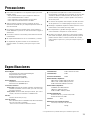
Precautions ........................................................................... 5
Specifications........................................................................ 5
The Panel Controls ............................................................... 6
■ Front Panel ........................................................................................ 6
■ Rear Panel ......................................................................................... 7
Setting Examples .................................................................. 8
Contents
Thank you for purchasing a Yamaha DG60-112 Guitar Amplifier.
Originally conceived and entirely designed by Yamaha, the DG60-112 is a digital
guitar amplifier that delivers powerful tube amp tone with superior stability com-
pared to other tube amplifiers.
Equipped with 2 independent channels, each channel offers 8 different preset amp
types from which you can choose and create tone with. Along with digital spring
reverb that can be applied to each channel is capable of producing a wide range of
tone. Foot switches connected to the foot switch jacks can be used to switch between
channels and switch the reverb ON/OFF. It also features a line out jack equipped with
a speaker simulator. Altogether, the DG60-112 is a versatile guitar amplifier that can
be used in studio as well as live situations.
To get the best results and longest life out of your DG60-112, we recommend that you
carefully read this manual, and keep it in a safe place for future reference.

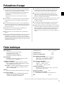
5
● Avoid using your amplifier in the following locations to prevent
possible damage:
• In direct sunlight or next to heating equipment.
• Extremely cold or hot locations.
• Locations exposed to high humidity or excessive dust.
• Locations subject to strong shocks or vibration.
● Before making any connections, make sure that the power on the
amplifier and any external devices is switched OFF.
● To protect the speaker from possible damage, always set the
MASTER knob to “0” before switching the power ON/OFF.
● When connecting a speaker to this unit make sure to turn OFF
the power first.
● Do not apply excessive force to the switches and controls.
● Your Yamaha guitar amplifier is a precision musical instrument.
Handle it with care and avoid dropping or bumping it.
Precautions
● Operating temperatures will rise during use. Make sure the
amplifier is used in a well-ventilated area. The DG60-112 should
be placed in a position were there is at least 30cm (12”) clear-
ance from the wall on the sides, top and back of the amplifier.
● For safety, always remove the power plug from the AC wall
outlet if there is any danger of lightning striking in your area.
● Keep the amplifier away from neon signs or fluorescent lighting
to prevent noise pickup.
● To prevent damage and possibly electrical shock, never open the
case and tamper with the internal circuitry.
● Never use benzene, thinner or other volatile liquids for cleaning,
as these chemicals may cause damage or discoloration to the
finish. Always use a dry, soft cloth to wipe off dust and dirt.
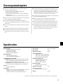
Digital Section
Complete Digital Signal Processing
Amplification Type : Internal 8 Channel Preset
Digital Reverb (SPRING)
Speaker Simulator (LINE OUT)
Analog Section
60W Solid State Power Amp
30 cm Speaker (EMINENCE) x 1
Controller/Switch
Front Panel : GAIN, MASTER, TREBLE, HIGH MID, LOW MID,
BASS, PRESENCE, REVERB, AMP select switch, for each
channel (A/B), Channel select switch (A/B)
Rear Panel : EFFECT BLEND, SP MUTE switch, for each
channel (A/B), EFFECT SEND/RETURN level switch
Indicator
Peak Level Display LED (Red)
Connection Jacks
INPUT HIGH/LOW, EFFECT SEND/RETURN, LINE OUT/
PHONES, FOOT SW (CH SELECT, REVERB)
: All Standard Phone Mono Jack
A/D Converter 20 bit + 3 bit floating
D/A Converter 20 bit
Sampling Frequency 48 kHz
Input Level/Impedance
INPUT HIGH: –20dBm (THRU)/1MΩ
INPUT LOW: –10dBm (THRU)/1MΩ
EFFECT RETURN: 0dBm/120kΩ
Output Level/Impedance
SPEAKER: 60W RMS/8Ω
LINE OUT: +2dBm/47Ω
EFFECT SEND: –2dBm/1kΩ
Power Requirements
U.S. and Canadian models : 120V, 60Hz
General model : 230V, 50Hz
Power Consumption
70W
Dimensions (W x H x D)
540 x 504 x 276 mm (21.3” x 19.8” x 10.9”)
Weight
18.0 kg (39 lbs 11 oz)
Specifications
* Specifications and external appearance are subject to change without notice.

6
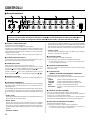
q Input Jack (INPUT HIGH, LOW)
The amplifier’s input jack.
The guitar is connected to the amplifier here. Guitars with a high output
should be connected to the LOW jack while guitars with a low output
should be connected to the HIGH jack. If you want a clean tone we
recommend connecting the guitar to the LOW jack.
* Always switch the power off before connecting the guitar.
w Peak Indicator
This indicator is used to match the input level. The indicator lights when
the peak level is exceeded.
e Channel Select Switch
Use to switch between Channels A and B.
Press the switch to select the channel you want to use.
When Channel A ( ) is selected, the amplifier will produce tone accord-
ing to the settings specified by the upper row of knobs
t – o
. When
Channel B( ) is selected, the amplifier will produce tone according to
the settings specified by the lower row of knobs
t – o
.
r Channel Indicator
The indicator lamp corresponding to the currently selected channel lights.
t Amp Select Switch
Use to select one of the 8 internal preset guitar amp types.
With any of the amp types, basically 2 is brighter than 1.
Depending upon the control settings, as shown in “Setting Examples”
on the page 8, the tone character that is possible is wider than what the
amp type’s name implies.
• LEAD1, LEAD2
Lead offers a tone with heavy distortion. Substantial mids provide a fat
tone with excellent sustain.
• DRIVE1, DRIVE2
Drive offers a thick overdrive tone with excellent sustain similar to when
the volume is fully raised on a tube amplifier. Using the tone control
knobs to adjust the balance of their respective frequencies creates a
wider variety of tone.
• CRUNCH1, CRUNCH2
Crunch offers expressive picking articulation and nuance. Raise the
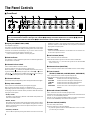
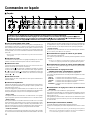
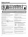
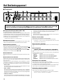
The Panel Controls
■ Front Panel
e
r t iyq
w
u o
!0
The DG60-112 is a high-quality guitar amp with 2 independent channels.
You can switch between channel A (the upper row of knobs t-o) settings and channel B (the lower row of knobs t-o) with the
switch e or with a foot-switch. Control knobs t-o for both channels A and B operate in the same manner.
GAIN level creates a tone similar to that natural overdrive when the
volume is raised on a tube amplifier. This crisp tone is excellent for
playing riffs and rhythm parts.
• CLEAN1, CLEAN2
A clean sound without distortion. Use an effect such as reverb or cho-
rus to create a spacious sound.
y Gain Volume (GAIN)
Use to control the amount of distortion.
Rotate the knob to the right to increase the amount of distortion.
* If the GAIN is set to “0”, sound will not be produced even of the MASTER
Volume is turned up.
u Master Volume (MASTER)
Use to control the overall volume of the GAIN and tone control settings.
i Tone Controls
(TREBLE, HIGH MID, LOW MID, BASS, PRESENCE)
Use to control the levels of their respective frequencies.
Rotate the knob to the right to increase the level of tone.
TREBLE Controls the level of the high frequencies.
HIGH MID Controls the level of the upper mid frequencies.
LOW MID Controls the level of the lower mid frequencies.
BASS Controls the level of the low frequencies.
PRESENCE Controls the level of the frequencies higher than
TREBLE.
o Reverb Volume (REVERB)
Use to control the amount of reverb (Spring Reverb).
Rotate the knob to the right to increase the amount of reverb. If the knob
is set to “0”, no reverb will be produced.
Reverb can also be switched ON/OFF with a foot switch connected to
the FOOT SW REVERB jack located on the rear panel.
!0 Power Switch (POWER)
The main unit’s power switch.
Press the switch to turn the amp ON/OFF.
* To protect the speakers make sure the MASTER Volume is set to “0”before
you switch the power ON/OFF.

7
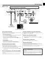
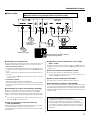
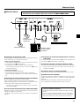
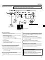
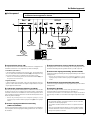
■ Rear Panel
The Panel Controls
Before making any connections, make sure that the power on the DG60-112
and any external devices is switched OFF.
!1 Foot Switch (FOOT SW)
The following functions can be switched with an optional foot switch
(Yamaha FS1, etc.) connected to these jacks.
• Channel Select (CH SELECT)
You can easily switch between Channels A and B in the same manner
as the Channel Select Switch e on the front panel.
Step on the foot switch to switch between Channels A/B.
* When the foot switch is used, the Channel Select Switch e on the front
panel is inactive.
• Reverb (REVERB)
You can switch the Reverb ON/OFF.
Stepping on the foot switch switches the Reverb ON/OFF.
When the Reverb is switched OFF, no reverb will be produced.
!2 Speaker Mute Switch (SP MUTE)
Press the switch to mute output from the speaker.
Insert a thin object inside the hole to press the switch.
Use this switch in conjunction with the headphones or Line Out when
you don’t want sound produced by the DG60-112’s speaker.
* When speaker output is muted, output to the EFFECT SEND jack !5 will
be muted as well.
!3 Line Out/Head Phone Jack (LINE OUT/PHONES)
Use this jack to connect directly to a mixer’s line jack or use a pair of
headphones.
The line signal from this jack passes through a *speaker simulator.
!4 Effect Send/Return Level Switch (0dB/-20dB)
The output level of the Send Jack !5 and the input level of the Return
Jack !6 can be set to –20dB or 0dB.
!5 Effect Send Jack (EFFECT SEND)
Connect an external effector’s input jack to this jack.
* When speaker output is muted, output to the EFFECT SEND jack !5 will
be muted as well.
!6 Effect Return Jack (RETURN)
Connect an external effector’s output jack to this jack.
!7 Blend Knob (BLEND)
Use this knob to control the amount of signal that is received from the
effect return and added to the DG60-112’s amp signal.
Rotate the knob toward the EFFECT side to add more effect to the tone.
Rotate the knob toward the DRY side for tone without effect.
* What is a Speaker Simulator?
The speaker simulator adds the live nuance of a speaker to the
line signal.
When you connect the DG60-112 directly to a mixer or MTR the
speaker simulator will add the acoustic characteristics of a speaker,
as heard through a microphone, to the tone.
!1
!2
Effect Unit
IN
OUT
P. A. Mixer or Recording Device
Headphones
!4
!5 !6!3 !7
Channel A/B selection
Reverb on/off

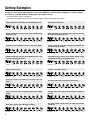
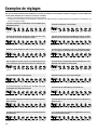
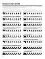
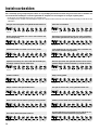
8
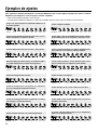
Setting Examples
To help you start enjoying the fantastic sound of the DG60-112, here are some examples of common settings.
Use these as a starting point in creating your own original sounds.
* Set the Master Volume control to a suitable level.
* The setting can be changed to suit the guitar you use. Find your optimum setting by referring to the sample settings.
LEAD1 10.0 – 10.0 6.8 8.7 10.0 10.0 5.1
LEAD2 9.0 – 5.0 6.4 2.0 6.5 5.0 4.0
LEAD2 3~8 – 7.0 2.0 2.0 5.5 7.0 3.0
DRIVE1 10.0 – 9.7 1.5 8.2 7.5 6.5 4.0
DRIVE1 8.7 – 7.0 7.5 7.5 7.4 7.1 4.2
DRIVE2 10.0 – 9.2 8.5 4.0 7.3 5.6 4.4
DRIVE2 4.9 – 7.0 7.0 8.1 7.7 9.0 3.2
CRUNCH1 9.3 – 9.3 9.0 8.1 3.9 7.4 5.1
CLEAN2 10.0 – 4.9 5.3 8.6 3.9 3.6 4.1
CLEAN2 5.4 – 7.2 8.3 10.0 4.9 5.0 3.2
CLEAN1 5.3 – 5.7 0.9 3.0 9.5 9.9 3.1
CRUNCH2 2.6 – 2.7 7.5 9.2 7.3 1.7 4.2
CRUNCH2 3.0 – 9.3 4.7 1.6 6.5 7.3 3.4
CRUNCH1 3.5 – 7.0 4.0 2.0 3.0 4.0 4.0
CLEAN1 5.4 – 10.0 8.2 8.9 8.1 5.8 4.7
LEAD1 10.0 – 10.0 5.8 1.9 10.0 10.0 5.5
A typical distortion sound often used in British hard rock.
Ideally smooth lead sound for solos with sustains using
the front pickup.
A brilliant sound suitable for hard rock and heavy metal.
Optimum distortion for heavy riffs with the gain up, crisp
overdrive with the gain down.
Tight overdrive sound.
A punchy overdrive sound with rich overtones in the mid
range.
A hard overdrive sound emphasizing the low and high
ranges.
Texas blues type sound with slight overdrive.
All-round crunch sound.
The warm and clean sound of a crunch amp. Can be used
for all genres from jazz to rock.
Crunch sound like a low-power vintage amp with the vol-
ume turned up all the way.
Contemporary jazz sound. Can be used to obtain a clean
sound without using the CLEAN channel.
Country sound with a punch.
A rich and clean bass sound used in hard rock.
A bright, clean sound. Can be used widely in a number of
scenes.
The natural, light crunch sound of a clean amp with the
volume up.

AMPLIFICATEUR DE GUITARE
Mode d’emploi

10
Précautions d’usage........................................................... 11
Fiche technique................................................................... 11
Commandes en façade....................................................... 12
■ Façade ............................................................................................. 12
■ Face arrière ..................................................................................... 13
Exemples de réglages ........................................................ 14
Table des matières
Nous vous remercions d’avoir fait l’acquisition de l’amplificateur de guitare DG60-112
Yamaha.
Conçu initialement et entièrement réalisé par Yamaha, le DG60-112 est un amplificateur de
guitare numérique capable de délivrer des sons tout aussi puissants que ceux des amplifica-
teurs à lampes tout en offrant une stabilité de fonctionnement supérieure comparée à celle
des autres types d’amplificateurs à lampes. Doté de 2 canaux indépendants, chacun des ca-
naux offre un choix de huit différents préréglages d’amplification qui vous permettent de
choisir et de créer une grande variété de sons originaux. Les interrupteurs au pied raccordés
aux prises d’interrupteur au pied permettent d’effectuer une commutation entre les canaux et
d’activer ou de désactiver la réverbération. L’amplificateur de guitare se présente également
avec une prise de sortie de ligne équipée d’un simulateur de haut-parleur. Le DG60-112
dans son intégralité est un amplificateur de guitare d’une grande souplesse qui lui permet
d’être utilisé autant dans un studio qu’à l’occasion de concerts.
Pour avoir la certitude d’obtenir les meilleurs résultats possibles et assurer à votre DG60-
112 une longévité optimale, nous vous recommandons de lire attentivement ce mode d’em-
ploi et par ailleurs, de le conserver dans un endroit sûr à des fins de consultation ultérieure.

11
● Pour éviter tout risque d’endommagement de votre amplificateur,
évitez de vous en servir dans les endroits mentionnés ci-dessous :
• En plein soleil ou près d’un appareil de chauffage.
• Dans les lieux à température extrême, basse comme élevée.
• Dans les lieux à très forte humidité ou excessivement
poussérieux.
• Dans les lieux soumis à des chocs violents ou de fortes
vibrations.
● Avant d’effectuer le moindre branchement, vérifiez que l’alimenta-
tion du DG60-112 et de tous les appareils extérieurs est bien
coupée.
● Par mesure de précaution et de façon à ne pas endommager les
haut-parleurs, positionnez toujours le potentiomètre de réglage de
niveau de sortie MASTER sur “0” avant de mettre l’appareil sous
tension ou de l’arrêter.
● N’oubliez pas de couper l’alimentation de l’amplificateur au
préalable avant de raccorder un haut-parleur.
● Ne forcez jamais sur les commutateurs et les commandes de
réglage.
● Notez que la température des appareils croît au fur et à mesure de
leur utilisation. Par conséquent, vous devez vous assurer que
l’amplificateur est utilisé dans un endroit bien aéré. Le DG60-112
doit être disposé de telle sorte qu’un espace d’au moins 30 cm soit
aménagé entre le mur et l’appareil, autant sur les côtés, au-dessus
que derrière l’amplificateur.
Précautions d’usage
● Votre amplificateur de guitare Yamaha est un instrument musical
de haute précision. Vous devez le manipuler délicatement et
surtout éviter de le buter voire de le laisser tomber par terre.
● Par mesure de sécurité, premez toujours la précaution de
débrancher la prise d’alimentation secteur de la prise murale
utilisée pour l’alimentation si la foudre risque de tomber dans la
région où vous utilisez votre instrument.
● Éloignez l’amplificateur des enseignes lumineuses au néon ou des
dispositifs d’éclairage à lampes fluorescentes afin de ne pas
recueillir de parasites.
● Pour éviter tout risque d’endommagement voire d’électrocution,
n’ouvrez jamais le coffret ni ne modifiez les circuits internes.
● N’utilisez jamais de benzène, diluant chimique ou autres produits
volatiles pour effectuer l’entretien de l’appareil car ceci aurait pour
effet de l’endommager voire de provoquer une décoloration de la
finition extérieure. L’accumulation de poussière et les taches
doivent être retirées de l’appareil avec un morceau d’étoffe sec et
souple.
Fiche technique
Étage numérique
Traitement de signal numérique intégral
Préréglage interne de 8 canaux
Réverbération numérique (SPRING)
Simulateur de haut-parleur (LINE OUT)
Étage analogique
Amplificateur de puissance à semi-conducteurs de 60 W
Haut-parleur de 30 cm (EMINENCE) : 1
Contrôleur / Commutateurs
Façade : GAIN, MASTER, TREBLE, HIGH MID, LOW MID,
BASS, PRESENCE, REVERB, sélecteur AMP pour chaque
canal (A/B), sélecteur de canal (A/B)
Face arrière : commutateurs EFFECT BLEND, SP MUTE pour
chaque canal (A/B), potentiomètre de réglage de niveau
EFFECT SEND/RETURN
Afficheur
Indicateur de crêtes à diodes électroluminescentes (rouges)
Prises de raccordement
INPUT HIGH/LOW, EFFECT SEND/RETURN, LINE OUT/
PHONES, FOOT SW (CH SELECT, REVERB)
: toutes prises de téléphone standard mono
Convertisseur A-N 20 bits + 3 bits flottants
Convertisseur N-A 20 bits
Fréquence d’échantillonnage 48 kHz
Niveau d’entrée / d’impédance
INPUT HIGH : – 20 dBm (THRU) / 1 Mégohms
INPUT LOW : – 10 dBm (THRU) / 1 Mégohms
EFFECT RETURN : 0 dBm / 120 k-ohms
Niveau de sortie / d’impédance
SPEAKER : 60 W efficace / 8 ohms
LINE OUT : + 2 dBm / 47 ohms
EFFECT SEND : – 2 dBm / 1 k-ohms
Conditions d’alimentation
Modèles pour les États-Unis et le Canada : 120 V, 60 Hz
Modèle général : 230 V, 50 Hz
Puissance consommée 70 W
Encombrement (avec les roulettes)
540 (largeur) x 504 (hauteur) x 276 (profondeur) mm
Poids 18,0 kg
* Sous réserve de modification des renseignements techniques et de l’aspect extérieur sans préavis.

12
Commandes en façade
■ Façade
Le DG60-112 est un amplificateur de guitare numérique de haut de gamme à 2 canaux indépendants.
Vous pouvez passer alternativement des réglages du canal A (réalisés avec les boutons de la rangée supérieure t-o ) aux
réglages du canal B (réalisés avec les boutons de la rangée inférieure t-o ), avec le commutateur e ou l’interrupteur au pied.
Les potentiomètres de réglage t-o contrôlant les deux canaux A et B agissent de la même façon.
q Prises d’entrée (INPUT HIGH, LOW)
Prises d’entrée des amplificateurs. Raccordez la guitare à l’amplificateur par
l’intermédiaire de cette prise. Les guitares à hauts niveaux de sortie doivent
être raccordées à la prise LOW tandis que les guitares à niveaux de sortie
réduits doivent être raccordées à la prise HIGH. Si vous désirez obtenir une
sonorité parfaite, nous vous recommandons d’effectuer le branchement à la
prise LOW.
* Placez toujours l’interrupteur d’alimentation en position OFF avant de bran-
cher la guitare.
w Indicateur de crêtes
Cet indicateur est utilisé pour faire un réglage d’équilibrage avec le niveau
d’entrée. L’indicateur s’allume lorsque le niveau de crête est dépassé.
e Sélecteur de canal
Il permet de passer alternativement du canal A au canal B et vice versa.
Enfoncez le sélecteur pour choisir le canal désiré.
Lorsque le canal A ( ) est sélectionné, l’amplificateur produira une sonorité
en fonction des réglages réalisés avec les boutons de la rangée supérieure
t – o. Lorsque le canal B ( ) est sélectionné, l’amplificateur produira une
sonorité en fonction des réglages réalisés avec les boutons de la rangée
inférieure t – o.
r Indicateur de canal
La lampe témoin de canal correspondant au canal qui est actuellement sé-
lectionné s’allume.
t Sélecteur d’amplificateur
Il permet de sélectionner l’un des 8 types d’amplificateur de guitare interne.
Parmi tous les types d’amplificateurs, en principe le numéro 2 produit un son
plus brillant que le numéro 1.
Suivant les réglages des potentiomètres qui sont indiqués avec les “ Régla-
ges types ” de la page 14, le caractère de la tonalité qu’il est possible d’obte-
nir est plus étendu que celui que le nom de l’amplificateur implique.
• LEAD1, LEAD2
Lead permet d’obtenir une tonalité avec une forte distorsion. Les réglages
moyens importants procurent une tonalité dense avec un excellent sustain.
• DRIVE1, DRIVE2
Drive permet d’obtenir une tonalité à distorsion dosable avec un excellent
sustain similaire à l’effet obtenu lorsque le volume est augmenté au maxi-
mum avec un amplificateur à lampe. L’utilisation des potentiomètres de ré-
glage de tonalité servant à des fins d’équilibrage de leurs fréquences res-
pectives a pour effet de produire une plus grande variété de tonalité.
• CRUNCH1, CRUNCH2
Crunch offre un choix expressif de l’articulation et de nuance de la tonalité.
Un accroissement du niveau GAIN produit une tonalité similaire à celle d’une
tonalité à distorsion dosable naturelle lorsque le volume est augmenté avec
un amplificateur à lampe. Cette nette tonalité est excellente pour jouer des
phrases musicales en solo d’improvisation et des passages rythmiques.
• CLEAN1, CLEAN2
Produit un son pur sans distorsion. Se servir d’un effet tel que la réverbéra-
tion ou le chorus pour obtenir un son spacieux.
y Potentiomètre de réglage de volume de gain (GAIN)
Sert à ajuster le taux de distorsion.
Une rotation du potentiomètre vers la droite permet d’augmenter le taux de
distorsion.
* Aucun son n’est délivré si le potentiomètre de réglage de GAIN est placé sur
“0” même si le réglage du potentiomètre de réglage MASTER est augmenté.
u Potentiomètre de réglage de volume général (MASTER)
Sert à ajuster le volume général du réglage de GAIN et des potentiomètres
de réglage de tonalité.
i Potentiomètres de réglage de tonalité
(TREBLE, HIGH MID, LOW MID, BASS, PRESENCE)
Servent à ajuster les niveaux de leurs fréquences respectives.
Une rotation du potentiomètre vers la droite permet d’augmenter le niveau
de la tonalité.
TREBLE Contrôle le niveau des fréquences élevées.
HIGH MID Contrôle le niveau des fréquences moyennes supérieures.
LOW MID Contrôle le niveau des fréquences moyennes inférieures.
BASS Contrôle le niveau des fréquences basses.
PRESENCE Contrôle le niveau des fréquences supérieures à celles de
TREBLE.
o Potentiomètre de réglage de volume de réverbération
(REVERB)
Sert à ajuster le taux de réverbération. (Spring Reverb).
Une rotation du potentiomètre vers la droite permet d’augmenter le taux de
réverbération. Aucune réverbération n’est produite si le potentiomètre de ré-
glage est placé sur “0”.
Il est également possible d’activer ou de désactiver la réverbération à partir
d’un interrupteur au pied raccordé à la prise FOOT SW REVERB implantée
sur la face arrière.
!0 Interrupteur d’alimentation (POWER)
Il s’agit de l’interrupteur d’alimentation général de l’appareil.
Appuyez sur l’interrupteur pour mettre l’amplificateur sous tension ou l’arrê-
ter.
* Par mesure de précaution et de façon à ne pas endommager les haut-parleurs,
réglez toujours le potentiomètre de réglage de niveau de sortie MASTER sur
“0” avant de mettre l’appareil sous tension ou de l’arrêter.
e
r t iyq
w
u o
!0

13
■ Face arrière
Commandes de la façade
Avant d’effectuer le moindre branchement, vérifiez que l’alimentation du
DG60-112 et de tous les appareils extérieurs est bien coupée.
* Qu’est-ce qu’un simulateur de haut-parleur ?
Le simulateur de haut-parleur a pour fonction de rajouter une nuance
directe au son d’un haut-parleur aux signaux de sortie de ligne.
Lorsque le DG60-112 est raccordé directement à une table de mixage
ou au MTR, le simulateur de haut-parleur ajoutera les caractéristi-
ques acoustiques d’un haut-parleur au son comme celui capté par un
microphone.
!1 Interrupteur au pied (FOOT SW)
Les fonctions décrites ci-dessous peuvent être commandées à partir d’un
interrupteur au pied optionnel (Yamaha FS1, etc.) raccordé à ces prises.
• Sélection de canal (CH SELECT)
Il est aisé de passer alternativement entre les canaux A et B exactement de
la même façon que le permet de le sélecteur de canaux e implanté en
façade.
Enfoncez l’interrupteur au pied pour passer alternativement entre les ca-
naux A et B ?
* Le sélecteur de canaux e implanté en façade est asservi lorsque l’interrupteur
au pied est utilisé.
• Réverbération (REVERB)
Vous pouvez activer ou désactiver la réverbération.
Enfoncez l’interrupteur au pied pour activer ou désactiver la réverbération.
Notez qu’aucune réverbération n’est produite lorsque la réverbération est
désactivée.
!2 Commutateur de coupure de haut-parleurs (SP MUTE)
Enfoncez le commutateur de manière à couper le son des haut-parleurs.
Introduisez un objet mince dans le trou pour actionner le commutateur.
Utilisez ce commutateur en même temps que le casque d’écoute ou la sortie
de ligne si vous ne voulez pas que le haut-parleur du DG60-112 délivre le
son.
* Lorsque la sortie des haut-parleurs est coupée, les signaux présents à la prise
EFFECT SEND !5 seront également coupés.
!3 Prise de sortie de ligne ou de casque d’écoute
(LINE OUT/PHONES)
Utilisez cette prise pour effectuer un raccordement direct à la prise de ligne
d’une table de mixage ou pour utiliser un casque d’écoute.
Les signaux de ligne provenant de cette prise circulent dans un simulateur
de haut-parleur.
!4 Sélecteur de niveau de transmission / retour d’effet
(0 dB / –20 dB)
Le niveau de sortie des signaux présents à la prise Send !5 et le niveau
d’entrée des signaux présents à la prise Return !6 peuvent être ajustés sur
–20 dB ou 0 dB.
!5 Prise de transmission d’effet (EFFECT SEND)
Raccordez la prise d’entrée d’un effecteur externe à cette prise.
* Lorsque la sortie des haut-parleurs est coupée, les signaux présents à la prise
EFFECT SEND !5 seront également coupés.
!6 Prise de retour d’effet (EFFECT RETURN)
Raccordez la prise de sortie d’un effecteur externe à cette prise.
!7 Potentiomètre de mélangeur d’effet (BLEND)
Utilisez ce potentiomètre de réglage pour ajuster la puissance des signaux
reçus par le retour d’effet et ajoutés à amplificateur DG60-112. Une rotation
du potentiomètre vers la position EFFECT permet d’accentuer de l’effet à la
tonalité. Une rotation du potentiomètre vers la position DRY pour obtenir une
tonalité sans effet.
Console à effets
Table de mixage de sonorisation extérieure
ou appareil d’enregistrement
Casque d’écoute
Sélection de canal A/B
Activation ou
désactivation de la
réverbération
!1
!2
IN
OUT
!4
!5 !6!3 !7

14
Exemples de réglages
Afin de vous aider à bénéficier des fantastiques sonorités du DG60-112, voici quelques exemples de réglages courants. Utilisez-les
comme point de départ pour composer vos propres sonorités.
* Réglez la commande générale de volume Master sur une position appropriée.
* Les réglages peuvent être modifiés à des fins d’adaptation à la guitare que vous utilisez. Recherchez les réglages optimums qui correspondent à votre instrument en vous
référant à ces exemples de réglage.
LEAD1 10.0 – 10.0 6.8 8.7 10.0 10.0 5.1
LEAD2 9.0 – 5.0 6.4 2.0 6.5 5.0 4.0
LEAD2 3~8 – 7.0 2.0 2.0 5.5 7.0 3.0
DRIVE1 10.0 – 9.7 1.5 8.2 7.5 6.5 4.0
DRIVE1 8.7 – 7.0 7.5 7.5 7.4 7.1 4.2
DRIVE2 10.0 – 9.2 8.5 4.0 7.3 5.6 4.4
DRIVE2 4.9 – 7.0 7.0 8.1 7.7 9.0 3.2
CRUNCH1 9.3 – 9.3 9.0 8.1 3.9 7.4 5.1
CLEAN2 10.0 – 4.9 5.3 8.6 3.9 3.6 4.1
CLEAN2 5.4 – 7.2 8.3 10.0 4.9 5.0 3.2
CLEAN1 5.3 – 5.7 0.9 3.0 9.5 9.9 3.1
CRUNCH2 2.6 – 2.7 7.5 9.2 7.3 1.7 4.2
CRUNCH2 3.0 – 9.3 4.7 1.6 6.5 7.3 3.4
CRUNCH1 3.5 – 7.0 4.0 2.0 3.0 4.0 4.0
CLEAN1 5.4 – 10.0 8.2 8.9 8.1 5.8 4.7
LEAD1 10.0 – 10.0 5.8 1.9 10.0 10.0 5.5
Sonorité à distorsion caractéristique souvent utilisée pour
le British hard rock.
Sonorité d’introduction progressive idéale pour les solos
avec sustain se servant du capteur d’entrée.
Brillante sonorité adaptée au hard rock et au heavy metal.
Distorsion optimum pour les phrases musicales en solo d’improvisation fortes avec
l’accroissement de gain et une distorsion dosable nette avec la réduction de gain.
Sonorité de distorsion dosable étroite.
Sonorité énergique de distorsion dosable avec des
surtonalités dans la gamme moyenne.
Dure sonorité de distorsion dosable accentuant les gammes
basse et haute.
Sonorité de type Blues Texas avec une sonorité de distorsion
dosable ténue.
Sonorité Crunch dans son ensemble.
Sonorité chaude et nette d’un amplificateur Crunch. Peut être
utilisée pour tous les genres de musiques, du jazz au rock.
Sonorité Crunch comparable à celle d’un amplificateur Vintage
avec un réglage de volume effectué sur une valeur maximum.
Sonorité de jazz contemporain. Permet d’obtenir une sono-
rité nette sans utiliser le canal CLEAN.
Sonorité Country avec une pointe d’énergie.
Sonorité riche et nette utilisée pour le hard rock.
Sonorité claire et nette. Peut être utilisée pour un grand nom-
bre de scènes.
Son Crunch naturel et modéré d’un amplificateur Clean avec
l’accroissement du volume.

GITARRENVERSTÄRKER
Bedienungsanleitung

16
Vorsichtsmaßregeln............................................................ 17
Technische Daten ............................................................... 17
Bedienelemente .................................................................. 18
■ Frontplatte........................................................................................ 18
■ Rückwand ........................................................................................ 19
Einstellungsbeispiele ......................................................... 20
INHALT
Zunächst möchten wir uns bei Ihnen dafür bedanken, daß Sie sich für den Gitarrenverstärker
DG60-112 von Yamaha entschieden haben.
Von seiner Grundkonzeption an eine Yamaha-eigene Entwicklung, ist der DG60-112 ein
digitaler Gitarrenverstärker, der kraftvolle Röhrenverstärker-Klänge mit einer Stabilität lie-
fert, mit der sich andere Röhrenverstärker nicht messen können. Das Gerät bietet 2 unabhän-
gige Kanäle mit jeweils 8 verschiedenen Verstärker-Presets, die Sie aufrufen und zur Er-
stellung eigener Sound-Variationen frei maßschneidern können. Zusammen mit dem Feder-
hall (Spring Reverb), das auf jeden Kanal gelegt werden kann, haben Sie weitreichende Klang-
variationsmöglichkeiten. Über Fußschalter, die an den entsprechenden Buchsen angeschlos-
sen sind, können Sie zwischen den Kanälen umschalten und das Reverb ein- und ausschalten.
Der Verstärker hat außerdem einen Line-Ausgang mit Lautsprecher-Simulator. Ihr DG60-
112 ist ein vielseitiger Gitarrenverstärker, der sowohl im Studio als auch auf der Bühne
seinen Man steht.
Um das Potential Ihres DG60-112 über Jahre hinweg voll ausschöpfen zu können, empfehlen
wir Ihnen, diese Anleitung aufmerksam durchzulesen und dann für später anfallende Fragen
gut aufzubewahren.

17
● Vermeiden Sie den Gebrauch des Verstärkers an folgenden
Orten, um eine mögliche Beschädigung zu vermeiden:
• In direkter Sonnenbestrahlung oder neben einem Heizkörper.
• An extrem kalten oder heißen Orten.
• An Orten, wo das Gerät hoher Feuchtigkeit oder übermäßiger
Staubeinwirkung ausgesetzt ist.
• An Orten, wo das Gerät starken Erschütterungen oder
Vibrationen ausgesetzt ist.
● Bevor Sie irgendwelche Anschlüsse machen, sollten Sie sich
stets vergewissern, daß der DG60-112 sowie alle externen
Geräte AUSgeschaltet sind.
● Zum Schutz der Lautsprecher vor möglichen Schäden stellen Sie
den MASTER-Regler auf “0”, bevor Sie das Gerät ein- oder
ausschalten.
● Schalten Sie das Gerät vor dem Anschluß eines Lautsprechers
AUS.
● Wenden Sie beim Betätigen der Schalter und Regler nicht zu viel
Kraft auf.
● Bei Ihrem Yamaha-Gitarrenverstärker handelt es sich um ein
Präzisionsgerät. Behandeln Sie ihn mit entsprechender Umsicht,
damit er nicht angestoßen oder durch einen Fall beschädigt wird.
Vorsichtsmaßregeln
● Der Verstärker erwärmt sich beim Betrieb. Achten Sie darauf,
daß das Gerät an einem gut belüfteten Platz steht. Der DG60-
112 sollte so aufgestellt werden, daß neben, vor und hinter dem
Verstärker jeweils mindestens 30 cm Freiraum verbleibt.
● Ziehen Sie zur Sicherheit stets den Netzstecker aus der Steckdo-
se, wenn ein Gewitter aufzieht.
● Achten Sie bei Gebrauch auf ausreichenden Abstand zu
Leuchtreklametafeln oder Leuchtstofflampen, um unerwünschte
Rauscheinstreuungen zu vermeiden.
● Um eine Beschädigung und einen möglichen elektrischen Schlag
zu vermeiden, öffnen Sie bitte niemals das Gehäuse und
vermeiden ein Berühren der internen Schaltungen.
● Verwenden Sie zum Reinigen des Geräts niemals Benzin,
Verdünner oder andere flüchtige Flüssigkeiten, da solche
Chemikalien die Gehäuseoberfläche angreifen und verfärben
können. Wischen Sie Staub und Schmutz mit einem trockenen,
weichen Lappen ab.
Technische Daten
Digitale Schaltungen
Volldigitale Signalverarbeitung
8 interne Preset-Programme
Digitales Reverb (SPRING)
Lautsprecher-Simulator (LINE OUT)
Analoge Schaltungen
Transistorisierte 60 W Endstufe
30 cm Lautsprecherchassis (EMINENCE) x 1
Regler/Schalter
Frontplatte: GAIN, MASTER, TREBLE, HIGH MID, LOW MID,
BASS, PRESENCE, REVERB und Verstärker-Wahlschalter
pro Kanal (A/B), Kanalwahlschalter (A/B)
Rückwand: EFFECT BLEND- und SP MUTE-Schalter pro Kanal
(A/B), EFFECT SEND/RETURN-Pegelschalter
Anzeige
Spitzenpegel-LED (rot)
Buchsen
INPUT HIGH/LOW, EFFECT SEND/RETURN, LINE OUT/
PHONES, FOOT SW (CH SELECT, REVERB)
: Alles Standard-Mono-Klinkenbuchsen
A/D-Umsetzer 20 Bit + 3 Bit gleitend
D/A-Umsetzer 20 Bit
Samplingfrequenz 48 kHz
Eingangspegel/-impedanz
INPUT HIGH: –20 dBm (THRU)/1 MΩ
INPUT LOW: –10 dBm (THRU)/1 MΩ
EFFECT RETURN: 0 dBm/120 kΩ
Ausgangspegel/-impedanz
SPEAKER: 60 W RMS/8 Ω
LINE OUT: +2 dBm/47 Ω
EFFECT SEND: –2 dBm/1 kΩ
Netzanschlußwerte
Modelle für USA und Kanada: 120 V, 60 Hz
Allgemeines Modell: 230 V, 50 Hz
Leistungsaufnahme 70W
Abmessungen (mit Fußrollen)
540 (B) x 504 (H) x 276 (T) mm
Gewicht 18,0 kg
* Änderungen der technischen Daten und des äußeren Erscheinungsbilds ohne Vorankündigung vorbehalten.

18
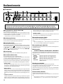
Bedienelemente
■ Frontplatte
Der DG60-112 ist ein qualitativ hochwertiger Gitarrenverstärker mit 2 unabhängigen Kanälen.
Sie können zum Umschalten zwischen Kanal A (Regler
t
bis
o
oben) und Kanal B (Regler
t
bis
o
unten) entweder
Schalter
e
oder aber einen Fußschalter verwenden. Die Regler
t
bis
o
haben für beide Kanäle identische Funktionen.
q Eingangsbuchse (INPUT, HIGH/LOW)
Hier wird die Gitarre angeschlossen.
Gitarren mit hohem Ausgangspegel sollten an die LOW-Buchse ange-
schlossen werden. Instrumente mit niedrigem Ausgangspegel sollten
an die HIGH-Buchse angeschlossen werden.
* Schalten Sie das Gerät vor dem Anschließen der Gitarre aus.
w Spitzenpegelanzeige
Diese Anzeige hilft beim Aussteuern des Eingangspegels. Die Anzeige
leuchtet, wenn der Spitzenpegel überschritten wird.
e Kanalwahlschalter
Zum Umschalten zwischen den Kanälen A und B.
Zum Auswählen des gewünschten Kanals drücken Sie diesen Schalter.
Wenn Kanal A gewählt ist ( ), erzeugt der Verstärker den mit den Reg-
lern
t
bis
o
in der oberen Reihe eingestellten Sound. Wenn Kanal B
gewählt ist ( ), erzeugt der Verstärker den mit den Reglern
t
bis
o
in
der unteren Reihe eingestellten Sound.
r Kanalanzeige
Diese Anzeige leuchtet, wenn der betreffende Kanal gewählt ist.
t Verstärker-Wahlschalter
Zum Auswählen eines der 8 Verstärker-Presets.
Für jeden Verstärkertyp gibt es jeweils zwei Variationen, wobei Variati-
on 2 einen helleren Klang liefert als Variation 1.
Mit entsprechenden Reglereinstellungen (siehe „Einstellungsbeispiele“
auf Seite 20) können Sie den Klangcharakter in einem wesentlich größe-
ren Rahmen variieren, als der jeweilige Verstärkertyp-Name andeutet.
• LEAD1, LEAD2
Die LEAD-Verstärkertypen liefern einen Sound mit viel Distortion
(Verzerrung). Solide Mitten bewirken einen satten Klang mit ausge-
zeichnetem Sustain (Nachklingverhalten).
• DRIVE1, DRIVE2
DRIVE bietet einen vollen Overdrive-Klang mit ausgezeichnetem
Sustain, ähnlich wie bei einem Röhrenverstärker mit voll aufgedrehter
Lautstärke. Mit den Klangreglern können für noch größere Klang-
variationen die einzelnen Frequenzbereiche gezielt abgeglichen wer-
den.
• CRUNCH1, CRUNCH2
CRUNCH erlaubt eine expressive Betonung und Nuancierung beim
Spielen. Heben des GAIN-Pegels erzeugt einen Klang, der dem na-
türlichen Overdrive eines mit hoher Lautstärkeeinstellung arbeitenden
Röhrenverstärkers ähnelt. Dieser knackige Sound eignet sich ausge-
zeichnet zum Spielen von Riffs und rhythmischen Parts.
• CLEAN1, CLEAN2
Ein reiner Klang ohne Distortion. Mit einem Effekt wie Reverb oder
Chorus läßt sich ein weiträumiger Sound erzielen.
y Verstärkungsregler (GAIN)
Zum Einstellen des Verzerrungsgrads.
Zum Verstärken des Verzerrungseffekts drehen Sie den Regler nach
rechts.
* Wenn der GAIN-Regler auf “0” steht, erzeugt das Gerät auch dann keinen
Ton, wenn der MASTER-Lautstärkeregler voll aufgedreht ist.
u Lautstärkeregler (MASTER)
Zur Regelung der Gesamtlautstärke des per GAIN- und Klangregler ein-
gestellten Tonsignals.
i Klangregler
(TREBLE, HIGH MID, LOW MID, BASS, PRESENCE)
Zum Einstellen des Signalpegels für den jeweiligen Frequenzbereich.
Zum Betonen eines Frequenzbereichs drehen Sie den entsprechenden
Regler nach rechts.
TREBLE Regelt den Pegel der oberen Hörfrequenzen.
HIGH MID Regelt den Pegel des oberen Mittenbereichs.
LOW MID Regelt den Pegel des unteren Mittenbereichs.
BASS Regelt den Pegel der Baßfrequenzen.
PRESENCE Regelt den Pegel der Frequenzen oberhalb des
TREBLE-Bereichs.
o Hallregler (REVERB)
Zur Einstellung der Stärke des Federhalls (Spring Reverb).
Zum Verstärken des Reverbs drehen Sie den Regler nach rechts. Wenn
der Regler auf “0” steht, wird kein Hall erzeugt.
Die Reverb-Stufe kann auch mit einem an der FOOT SW REVERB-
Buchse an der Rückwand angeschlossenen Fußschalter ein- und aus-
geschaltet werden.
!0 Netzschalter (POWER)
Schaltet die Stromversorgung ein und aus.
Drücken Sie diesen Schalter, um den Verstärker ein- und auszuschal-
ten.
* Zum Schutz der Lautsprecher vor möglichen Schäden stellen Sie den
MASTER-Regler auf “0”, bevor Sie das Gerät ein- oder ausschalten.
e
r t iyq
w
u o
!0

19
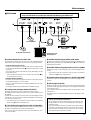
■ Rückwand
Bedienelemente
Bevor Sie irgendwelche Anschlüsse machen, sollten Sie sich stets vergewis-
sern, daß der DG60-112 sowie alle externen Geräte AUSgeschaltet sind.
* Was ist ein Lautsprecher-Simulator?
Ein Lautsprecher-Simulator bereichert das Line-Signal um den
Klangcharakter, den der Ton bei Wiedergabe über Lautsprecher
annehmen würde.
Wenn Sie den DG60-112 direkt an ein Mischpult oder Bandgerät
anschließen, versieht der Lautsprecher-Simulator das Tonsignal
mit dem akustischen Effekt eines Lautsprechers, den man bei
Tonaufnahme über ein Mikrofon vernimmt.
!1 Fußschalterbuchsen (FOOT SW)
Die folgenden Funktionen können mit einem an der jeweiligen Buchse
angeschlossenen Fußschalter (Yamaha FS1 usw.) gesteuert werden.
• Kanalumschaltung (CH SELECT)
Mit einem an dieser Buchse angeschlossenen Fußschalter können
Sie wie mit dem Kanalwahlschalter e zwischen den Kanälen A und B
umschalten.
Zum Umschalten auf den anderen Kanal (A oder B) betätigen Sie den
Fußschalter einmal.
* Wenn ein Fußschalter angeschlossen ist, hat der Kanalwahlschalter e an
der Frontplatte keine Funktion.
• Halleffekt EIN/AUS (REVERB)
Mit einem an dieser Buchse angeschlossenen Fußschalter können
Sie die Reverb-Stufe ein- und ausschalten.
Zum Ein- oder Ausschalten des Halleffekts betätigen Sie den Fuß-
schalter einmal.
Bei ausgeschalteter Reverb-Stufe wird kein Halleffekt erzeugt.
!2 Lautsprecher-Stummschalter (SP MUTE)
Mit dieser Taste können Sie den Lautsprecher stummschalten.
Zum Betätigen des Schalters stecken Sie einen spitzen Gegenstand in
die Öffnung.
Schalten Sie den Lautsprecher stumm, wenn Sie über Kopfhörer hören
oder den Ton mit einem externen System wiedergeben und der DG60-
112 keinen Ton erzeugen soll.
* Beim Stummschalten des Lautsprechers wird das Signal an der EFFECT
SEND-Buchse !5 ebenfalls stummgeschaltet.
!3
Line-/Kopfhörerausgangsbuchse (LINE OUT/PHONES)
Diese Buchse ermöglicht direkten Anschluß an den Line-Eingang eines
Mischpults oder Mithören des Signals über Kopfhörer.
Das an dieser Buchse anliegende Line-Signal durchläuft einen Laut-
sprecher-Simulator*.
!4 Effektschleifen-Pegelschalter (0dB/-20dB)
Mit diesem Schalter können Sie den Ausgangspegel der SEND-Buchse
!5 und den Eingangspegel der RETURN-Buchse !6 auf -20 dB oder 0
dB (Dämpfung) einstellen.
!5 Effektschleifen-Ausgangsbuchse (EFFECT SEND)
Diese Buchse wird mit dem Eingang eines externen Effektgeräts ver-
bunden.
* Beim Stummschalten des Lautsprechers wird das Signal an der EFFECT
SEND-Buchse !5 ebenfalls stummgeschaltet.
!6
Effektschleifen-Eingangsbuchse (EFFECT RETURN)
Diese Buchse wird mit dem Ausgang eines externen Effektgeräts ver-
bunden.
!7 Mischregler (BLEND)
Mit diesem Regler wird der Anteil des durch die externe Effektschleife
gehenden Signals eingestellt, der wieder in das Hauptsignal des DG60-
112 eingemischt wird.
Zum Verstärken des externen Effekts drehen Sie den Regler in Rich-
tung EFFECT.
Zum Abschwächen des externen Effekts drehen Sie den Regler in Rich-
tung DRY.
Effektgerät
PA-Mischpult oder
Aufnahmegerät
Kopfhörer
Kanal-A/B-Umschaltung
Reverb EIN/AUS
!1
!2
IN
OUT
!4
!5 !6!3 !7

20
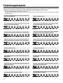
Einstellungsbeispiele
Die folgenden Beispiele für übliche Einstellungen sollen Ihnen den Einstieg in die phantastische Klangwelt des DG60-112
erleichtern. Verwenden Sie die Einstellungen als Ausgangsbasis bei der Erstellung eigener Sounds.
* Stellen Sie den MASTER-Regler auf eine passende Lautstärke ein.
* Die idealen Einstellungen fallen je nach Gitarre anders aus. Die Beispiele in der folgenden Übersicht sollen Ihnen bei der Suche nach den optimalen
Einstellungen helfen.
LEAD1 10.0 – 10.0 6.8 8.7 10.0 10.0 5.1
LEAD2 9.0 – 5.0 6.4 2.0 6.5 5.0 4.0
LEAD2 3~8 – 7.0 2.0 2.0 5.5 7.0 3.0
DRIVE1 10.0 – 9.7 1.5 8.2 7.5 6.5 4.0
DRIVE1 8.7 – 7.0 7.5 7.5 7.4 7.1 4.2
DRIVE2 10.0 – 9.2 8.5 4.0 7.3 5.6 4.4
DRIVE2 4.9 – 7.0 7.0 8.1 7.7 9.0 3.2
CRUNCH1 9.3 – 9.3 9.0 8.1 3.9 7.4 5.1
CLEAN2 10.0 – 4.9 5.3 8.6 3.9 3.6 4.1
CLEAN2 5.4 – 7.2 8.3 10.0 4.9 5.0 3.2
CLEAN1 5.3 – 5.7 0.9 3.0 9.5 9.9 3.1
CRUNCH2 2.6 – 2.7 7.5 9.2 7.3 1.7 4.2
CRUNCH2 3.0 – 9.3 4.7 1.6 6.5 7.3 3.4
CRUNCH1 3.5 – 7.0 4.0 2.0 3.0 4.0 4.0
CLEAN1 5.4 – 10.0 8.2 8.9 8.1 5.8 4.7
LEAD1 10.0 – 10.0 5.8 1.9 10.0 10.0 5.5
Ein typischer Distortion-Sound, dem man im britischen
Hard-Rock oft begegnet.
Ein schwungvoller Lead-Sound, ideal für Solos mit
Sustain (vorderer Tonabnehmer).
Ein brillanter Klang geeignet für Hard-Rock und Heavy-Metal.
Optimaler Distortion-Sound für dramatische Riffs bei
hohem Gain, knackiger Overdrive bei schwachem Gain.
Straffer Overdrive-Sound.
Ein wuchtiger Overdrive-Sound mit satten Obertönen im
Mittenbereich.
Ein harter Overdrive-Sound mit Betonung der unteren und
mittleren Frequenzen.
Texas Blues-Sound mit etwas Overdrive.
Allround-Crunch-Sound.
Der warme und reine Klang eines Crunch-Amps. Eignet
sich für alle Richtungen von Jazz bis Rock.
Crunch-Sound wie bei einem weniger leistungsstarken
Vintage-Amp mit voll aufgedrehter Lautstärke.
Zeitgenässischer Jazz-Sound. Eine Alternativeinstellung
zum CLEAN-Kanal, wenn ein reiner Klang gewünscht ist.
Country-Sound mit Pep.
Ein voller und reiner Baß-Sound, wie er in Hard-Rock ein-
gesetzt wird.
Ein heller, reiner Klang. Kann für eine Reihe von Musik-
richtungen verwendet werden.
Der natürliche, leichte Crunch-Sound eines Clean-Amps
mit aufgedrehter Lautstärke.
Strona się ładuje...
Strona się ładuje...
Strona się ładuje...
Strona się ładuje...
Strona się ładuje...
Strona się ładuje...
Strona się ładuje...
Strona się ładuje...
Strona się ładuje...
Strona się ładuje...
Strona się ładuje...
Strona się ładuje...
Strona się ładuje...
Strona się ładuje...
Strona się ładuje...
Strona się ładuje...
Strona się ładuje...
Strona się ładuje...
Strona się ładuje...
Strona się ładuje...
-
 1
1
-
 2
2
-
 3
3
-
 4
4
-
 5
5
-
 6
6
-
 7
7
-
 8
8
-
 9
9
-
 10
10
-
 11
11
-
 12
12
-
 13
13
-
 14
14
-
 15
15
-
 16
16
-
 17
17
-
 18
18
-
 19
19
-
 20
20
-
 21
21
-
 22
22
-
 23
23
-
 24
24
-
 25
25
-
 26
26
-
 27
27
-
 28
28
-
 29
29
-
 30
30
-
 31
31
-
 32
32
-
 33
33
-
 34
34
-
 35
35
-
 36
36
-
 37
37
-
 38
38
-
 39
39
-
 40
40


Yamaha DG60 Instrukcja obsługi
- Kategoria
- Instrumenty muzyczne
- Typ
- Instrukcja obsługi
- Niniejsza instrukcja jest również odpowiednia dla
w innych językach
- čeština: Yamaha DG60 Návod k obsluze
- español: Yamaha DG60 El manual del propietario
- italiano: Yamaha DG60 Manuale del proprietario
- Deutsch: Yamaha DG60 Bedienungsanleitung
- svenska: Yamaha DG60 Bruksanvisning
- português: Yamaha DG60 Manual do proprietário
- français: Yamaha DG60 Le manuel du propriétaire
- Türkçe: Yamaha DG60 El kitabı
- English: Yamaha DG60 Owner's manual
- dansk: Yamaha DG60 Brugervejledning
- русский: Yamaha DG60 Инструкция по применению
- Nederlands: Yamaha DG60 de handleiding
- română: Yamaha DG60 Manualul proprietarului
Powiązane artykuły
-
Yamaha DG100-212 Instrukcja obsługi
-
-
-
-
-
-
-
-
-
Yamaha THR10II instrukcja obsługi
Inne dokumenty
-
Ibanez IBZ10G(2019) Instrukcja obsługi
-
Ibanez IBZ10G(2019) Instrukcja obsługi
-
-
-
-
TC-Helicon TC HELICON Harmony Singer 2 Vocal Processors Skrócona instrukcja obsługi
-
 Earthquaker Devices Westwood Instrukcja obsługi
