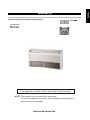
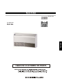
Airwell 30K Installation Instructions Manual
- Kategoria
- Klimatyzatory typu split
- Typ
- Installation Instructions Manual
Ten podręcznik jest również odpowiedni dla

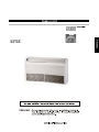
INSTALLATION INSTRUCTION
NOTE: This manual is for the single split application.
For multi split applications please use installation manual supplied
within outdoor unit package.
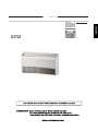
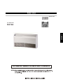
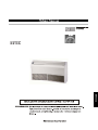
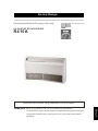
DC Inverter Split system for Wall / ceiling mounting
The appliance shall not be installed in the laundry.
DC INVERTER
R410A
ENGLISH

GENERAL RECOMMENDATIONS
- Congratulations for having selected an our air conditioner.
SAFETY DIRECTIONS
- Follow the safety rules in force when you are working on your appliance.
- Installation and maintenance of the equipment must only be performed by qualified specialists in
accordance with the rules of good workmanship and prevailing standards and instructions.
- Make sure that the power supply and its frequency are adapted to the required electric current of
operation, taking into account specific conditions of the location and the current required for any
other appliance connected with the same circuit.
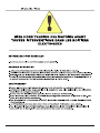
WARNING
- Cutoff power supply before starting to work on the appliance. The manufacturer declines any
responsibility and the warranty becomes void if these instructions are not respected.
- If you meet a problem, please call the Technical Department of your area.
- If possible, assemble the mandatory or optional accessories before placing the appliance on its
final Iocation.(see instruc- tions provided with each accessory)
- In order to become fully familiar with the appliance, we suggest to read also our Technical
Instructions.
- The information contained in these Instructions are subject to modification without advance notice.
IT IS MANDATORY TO CUT OFF POWER SUPPLY
BEFORE STARTING TO WORK IN THE ELECTRIC
CASING BOXES.
2
- For appliances with supplementary heaters, the minimum clearance from the appliance to
combustible is 50cm other wise, it will cause fire.

Do not attempt to install this air conditioner by yourself.
This unit contains no user-serviceable parts. Always consult authorized service personnel for repairs.
When moving, consult authorized service personnel for disconnection and installation of the unit.
Do not become excessively chilled by staying for lengthy periods in the direct cooling airflow.
Do not insert fingers or objects into the outlet port or intake grilles.
Do not start and stop air conditioner operation by disconnecting the power supply cord and so on.
Take care not to damage the power supply cord.
In the event of a malfunction (burning smell, etc.),immediately stop operation, disconnect the power supply plug, and consult authorized
service personnel.
If the power supply cord of this appliance is damaged, it should only be replaced by the authorized service personal, since special purpose
tools and specified cord are required.
Provide occasional ventilation during use.
Do not direct air flow at fireplaces or heating apparatus.
Do not climb on, or place objects on, the air conditioner.
Do not hang objects form the indoor unit.
Do not set flower vases or water containers on top of air conditioners.
Do not expose the air conditioner directly to water.
Do not pull power supply cord.
Turn off power source when not using the unit for extended periods.
Check the condition of the installation stand for damage.
Do not place animals or plants in the direct path of the air flow.
Do not drink the water drained from the air conditioner.
Do not use in applications involving the storage of foods, plants or animals, precision equipment,or art works.
Connection valves become hot during Heating; handle with care.
Do not apply any heavy pressure to radiator fins.
Operate only with air filters installed.
Do not block or cover the intake grille and outlet port.
Ensure that any electronic equipment is at least one metre away from either the indoor or outdoor units.
Avoid installing the air conditioner near a fireplace or other heating apparatus.
When installing the indoor and outdoor unit, take precautions to prevent access to infants.
Do not use inflammable gases near the air conditioner.
Danger This sign warns of death or serious injury.
Caution This sign warns of damage to property.
PRECAUTIONS
Set a suitable room temperature; excessively low room temperature is not good for your health and wastes electricity. Avoid frequent
setting of the temperature.
During cooling, avoid direct sun. Keep curtains and blinds closed. Close doors and windows to keep the cool air in the room.
Avoid generating heat or using of heating appliances while the air conditioner in cooling mode.
Make sure that the air flap is positioned properly: horizontal flow in cooling and downward vertical flow for heating.
Keep the room temperature uniform by adjusting the left/right vertical air blades.
Position the air flap and the left/right air blades in such a manner as to prevent your body from being exposed directly to air drafts.
During prolonged operation, ventilate the room occasionally by opening a window from time to time.
In a power failure, the microprocessor memory is retained. When restarted,operation will be resumed in the last mode of
operation. However, if the timer was used, the unit will be turned off by the timer only if the remote control is aimed at the
unit. Otherwise the power failure will cause the timer data to be erased from the microprocessor memory.
After turning on, allow more than 3 minutes for cooling, heating or dry operation to start.
When DRY mode is used, make sure that the room temperature is between 20 and 27 . When used out of this range,
the unit may protect itself and become inoperative.
When COOL or DRY modes are used, make sure that the room's relative humidity is below 78% lf the unit is used for a
prolonged periods of time in high humidity, moisture may form on the air outlet and drip down.
Remote control signals may not be received if the indoor unit controls cover is exposed to direct sunlight or strong light. ln
such a case, block the sunlight or dim the lighting.
The remote control is operative in a range of 8 meters. lf you are out of range, the remote control may have difficulties in
transmitting signals.
OPERATION TIPS
3
The appliance is not intended for use by young children of infirm persons without supervision.
Please pre-heat the air conditioner for at least 12 hours before operation. lf use it for a long time, please keep the power on.
ENGLISH

SUMMARY
DESCRIPTION
Installation/service tools.........................................................................................................................5
Operating temperature range................................................................................................................6
Dimensions of Indoor Unit .....................................................................................................................6
Dimensions of Outdoor Units.................................................................................................................6
INSTALLATION
Location of the Indoor Unit .................................................................................................................7-8
Location of the Outdoor Unit..................................................................................................................9
Refrigerant Line ...................................................................................................................................10
Installation.......................................................................................................................................1
Electrical Connections ....................................................................................................................
MAINTENANCE
Scheduled Maintenance .................................................................................................................
4

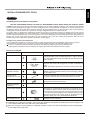
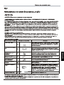
CAUTION
Incidentally, the "refrigerant cylinder" comes with the refrigerant designation (R410A) and protector coating in the
U.S's ARI specified rose color (ARI color code: PMS 507).
Also, the "charge port and packing for refrigerant cylinder" requires 1/2 UNF 20 threads per inch corresponding
to the charge hose's port size.
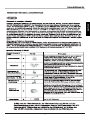
New Refrigerant Air Conditioner Installation
THIS AIR CONDTIONER ADOPTS THE NEW HFC REFRIGERANT (R410A) WHICH DOES NOT DESTROY OZONE
LAYER. R410A refrigerant is apt to be affected by impurities such as water, oxidizing membrane, and oils because the working
pressure of R410A refrigerant is approx. 1.6 times of refrigerant R22. Accompanied with the adoption of the new refrigerant, the
refrigeration machine oil has also been changed. Therefore, during installation work, be sure that water, dust, former refrigerant,
or refrigeration machine oil does not enter into the new type refrigerant R410A air conditioner circuit.
To prevent mixing of refrigerant or refrigerating machine oil, the sizes of connecting sections of charging port on main unit and
installation tools are different from those used for the conventional refrigerant units. Accordingly, special tools are required for
the new refrigerant (R410A) units. For connecting pipes, use new and clean piping materials with high pressure fittings made for
R410A only, so that water and/or dust does not enter. Moreover, do not use the existing piping because there are some
problems with pressure fittings and possible impurities in existing piping.
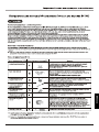
Changes in the product and components
In air conditioners using R410A, in order to prevent any other refrigerant from being accidentally charged, the service port
diameter size of the outdoor unit control valve (3 way valve) has been changed. (1/2 UNF 20 threads per inch)
In order to increase the pressure resisting strength of the refrigerant piping, flare processing diameter and
opposing flare nuts sizes have been changed. (for copper pipes with nominal dimensions 1/2 and 5/8)
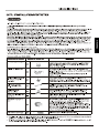
As the working pressure is high, it is impossible to measure the
working pressure using conventional gauges. In order to prevent
any other refrigerant from being charged, the port diameters have
been changed.
In order to increase pressure resisting strength, hose materials
and port sizes have been changed (to 1/2 UNF 20 threads per
inch).
When purchasing a charge hose, be sure to confirm the port size.
As working pressure is high and gasification speed is fast, it is
difficult to read the indicated value by means of charging cylinder,
as air bubbles occur.
The size of opposing flare nuts have been increased. Incidentally,
a common wrench is used for nominal diameters 1/4 and 3/8.
By increasing the clamp bar's receiving hole size, strength of
spring in the tool has been improved.
Used when flare is made by using conventional flare tool.
Connected to conventional vacuum pump. It is necessary to use
an adapter to prevent vacuum pump oil from flowing back into
the charge hose. The charge hose connecting part has two ports
-- one for conventional refrigerant (7/16 UNF 20 threads per inch)
and one for R410A. If the vacuum pump oil (mineral) mixes with
R410A a sludge may occur and damage the equipment.
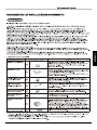
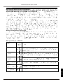
Exclusive for HFC refrigerant.
New tools for R410A Applicable to R22 model Changes
Gauge manifold
Charge hose
Electronic balance for
refrigerant charging
Torque wrench
(nominal dia. 1/2, 5/8)
Flare tool (clutch type)
Gauge for projection
adjustment
Vacuum pump adapter
Gas leakage detector
New tools for R410A
INSTALLATION/SERVICE TOOLS
5
ENGLISH

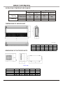
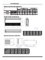
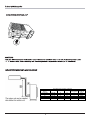
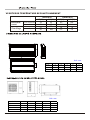
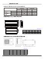
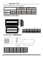
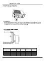
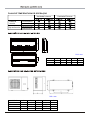
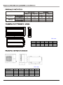
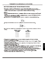
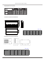
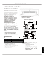
DIMENSIONS OF OUTDOOR UNITS
DIMENSIONS OF INDOOR UNIT
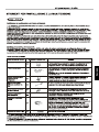
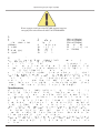
OPERATING TEMPERATURE RANGE
32
21
27
10
23
15
NANA
NA
NA
NA
46
-10
24
-15
18
-16
Indoor
Outdoor
Cooling
Heating
Upper Limit
Lower Limit
Upper Limit
Lower Limit
WB[ C]
O
DB[ C]
O
WB[ C]
O
DB[ C]
O
6
Unit: mm
Unit: mm
Item Model A B C D E
24/30K 980 427 790 610 395
36K 1107 440 1100 631 400
48K 958 412 1349 572 376
60K 1085 427 1365 620 395
Model A B C D H
24K 1220 225 1158 280 700
30/36K 1420 245 1354 280 700
48K 1700 245 1634 280 700

7
6XFKDSODFHZKHUHLVSHUPLWWLQJHDV\FRQQHFWLRQZLWK
WKHRXWGRRUXQLW
6XFKDSODFHZKHUHLVPRUPRUHDZD\IURPRWKHUHOHFWULF
DSSOLDQFHVVXFKDVWHOHYLVLRQDXGLRGHYLFHHWF
$YRLGDORFDWLRQZKHUHWKHUHLVKHDWVRXUFHKLJKKXPLGLW\
RULQIODPPDEOHJDV
'RQRWXVHWKHXQLWLQWKHLPPHGLDWHVXUURXQGLQJVRID
ODXQGU\DEDWKDVKRZHURUDVZLPPLQJSRRO
%HVXUHWKDWWKHLQVWDOODWLRQFRQIRUPVWRWKHLQVWDOODWLRQ
GLPHQVLRQGLDJUDP
7KHVSDFHDURXQGWKHXQLWLVDGHTXDWHIRUYHQWLODWLRQ
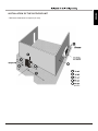
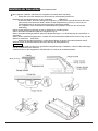
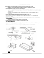
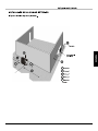
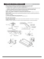
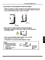
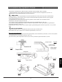
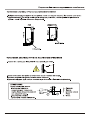
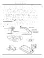
5HPRYHWKHVLGHSDQHOIL[LQJVFUHZDQGSXOOWR
WKHIURQWGLUHFWLRQDUURZGLUHFWLRQWRUHPRYH
/RRVHQWZRKDQJHUEUDFNHWVHWWLQJEROWV0
RQHDWKVLGHIRUOHVVWKDQPP5HPRYHWZR
KDQJHUEUDFNHWIL[LQJEROWV0RQWKHUHDUVLGH
'HWDFKWKHKDQJHUEUDFNHUE\SXOOLQJit EDFNZDUG
6XFKDSODFHZKHUHLV condersation water is easily drained
out.
Such a place that can handle the weight of indoor unit.
Such a place which has easy access for maintenance.
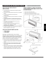
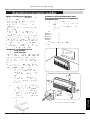
S
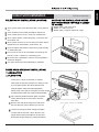
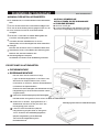
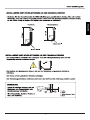
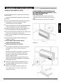
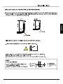
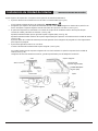
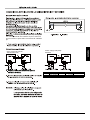
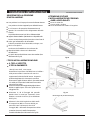
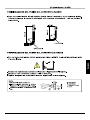
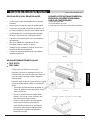
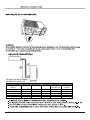
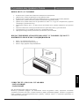
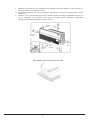
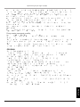
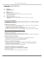
SELECTION OF INSTALLATION LOCATION.
THERE ARE 2 STYLES OF INSTALLATION.
CEILING TYPE
FLOOR TYPE
Each type is similar to the other as follows;
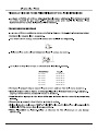
Determine the mounting position on ceiling or wall
by using paper pattern to indicate indoor frarne.
Mark the pattern and pull out the paper pattern.
Remove the return grill,the side panel and the hanger
bracket from the indoor unit as per procedure bellow.
Press the fixing knob of the relurn grilles, the grilles
will be opened wider and then pull it out from
the indoor.
CAUTION FOR INSTALLATION WHERE
AIR CONDITIONER TROUBLE IS LIKELY
TO OCCUR.
Where there is too much of oil.
Where it is acid base area.
Where there is irregular electrical supply.
Indoor Unit Instrallation2
3(5 INSTALLATION INSTRUCTIONS
6LGHSDQHOIL[LQJVFUHZ0
INSTALLATION
PAPER PLANK
100cm
or more
30cm
or more
60cm
or more
60cm
or more
150cm
or more
ENGLISH

8
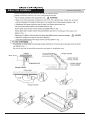
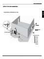
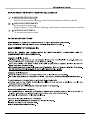
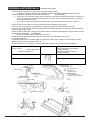
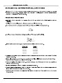
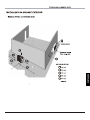
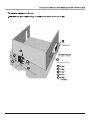
Indoor Unit Installation
,167$//$7,21,16758&7,216
6HWWKHVXVSHQVLRQEROW8VH:RU0VL]HVXVSHQVLRQEROWV
$GMXVWWKHGLVWaQFHIURPWKHXQLWWRWKHFHLOLQJVODEEHIRUHKDQG
)LJ25
40mm or less

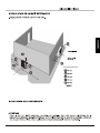
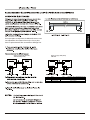
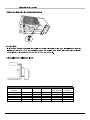
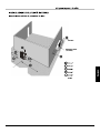
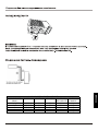
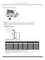
INSTALLATION OF THE OUTDOOR UNIT
- Minimum clearance to respect (in mm).
minimum
9
ENGLISH

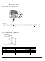
- The indoor unit may be installed above or below the unit
- The flare couplings are available as accessories in standard lengths of 2.5, 5 and 8m.
- The pipes are delivered coiled and equipped with flare nuts.
- Carefully uncoil the pipes in the opposite direction from the tums so as not to flatten them.
REFRIGERANT CONNECTIONS
10
DRAINING CONDENSATES
CAUTION
If the heat pump outdoor unit is installed in an area where the outdoor
temperature may fall below o + 1 C, it is mandatory to provide a system
preventing any risk of freezing of the condensate (e.g.heating wire).
NOM. CAPACITY
(kBtu/h)
024/030/036 3/8”-5/8” 30 15 5 60g/m
036T 3/8”-5/8” 30 15 5 60g/m
42 3/8”-5/8” 50 30 5 60g/m
48 3/8”-5/8” 50 30 5 60g/m
60 3/8”-3/4” 50 30 5 60g/m
MAXIMUM PIPES LENGTH & HEIGHT
TUBES O.D. LENGTH(A) LENGTH OF
PRECHARGE
ADDITIONAL
CHARGE
HEIGHT(B)

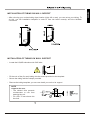
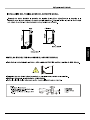
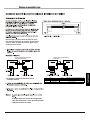
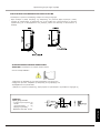
INSTALLATION OF TUBING ON WALL SUPPORT
- After choosing your coolant tubing input location (right, left or rear), you can set up your tubing. To
do this, use the installation template in order to form the tubes correctly and thus facilitate
connection.
11
- Fit the nuts of the (for med) tubing into the recess provided on the template.
- Secure the tubing with the clamps provided.
- Remove the tubing template; you can now install your unit on its support.
INSTALLATION OF TUBING ON WALL SUPPORT
- Locate the LIQUID tube above the GAS tube.
NOTE
output to the rear
- The slanted hole prevents
condensates or rain from
entering the unit.
- Fit a Dia. 70 mm sleeve into
the hole.
ENGLISH

2 Connect the vacuum pump with the flare coupling of the outdoor unit equipped with a process
valve.
3 Start the vacuum pump and check that the needle of the indicator goes down to - 0,2 mm Hg.
The pump should run during at least 15 minutes.
4 Before disconnecting the vacuum pump, check that the vacuum indicator remains in the same
position during five minutes.
5 Disconnect the vacuum pump.
6 Remove the cap of the "GAS" and "LIQUID" valves and open them with a hexagonal wrench to
free the R410A contained in the outdoor unit.
7 Check that the linking pipes are sealed. Use an electronic leak detector or a soapy sponge.
VACUUM OF COOLING PIPES AND INDOOR UNIT
- Only the outdoor unit is charged with R410A cooling fluid. The indoor unit contains a small quantity
of a neutral gas. This the reason it is imperative to vacuum the linking pipes and the indoor unit.
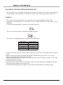
ASSEMBLY
- The outdoor unit is equipped with a valve allowing to vacuum the installation (large valve)
1 Connect the connecting pipes to the outdoor unit by FLARE NUTS and to the indoor unit by
BRAZING
- To obtain the right tightening, cover the sur face with cooling oil.
- The use of a counter wrench is required to tighten the valves.
- The values of the tightening torque are shown in the table below.
1
Pipe Diameter Tightening Torque
1/4Inch) 15-30 (N·m)
3/8Inch) 35-40 (N·m)
5/8Inch) 60-65 (N·m)
1/2Inch) 45-50 (N·m)
3/4Inch) 70-75 (N·m)
7/8Inch) 80-85 (N·m)

100
40
8
8
BA
L 30 m
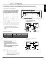
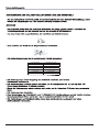
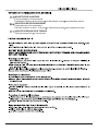
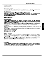
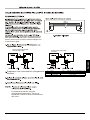
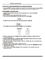
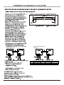
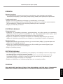
ELECTRICAL CONNECTION BETWEEN INDOOR AND OUTDOOR UNIT
ELECTRICAL REQUIREMENTS
Electrical wiring and connections should
be made by qualified electricians and in
accordance with local electrical codes
and regulation. The air conditioner units
must be grounded.
The air conditioner unit must be
connected to an adequate power outlet
from a separate branch circuit protected
by a time delay circuit breaker, as
specified on unit's nameplate.
Voltage should not vary beyond 10% of
the rated voltage.
An all-pole disconnection switch having a
contact separation of at least 3mm in all
poles should be connected in fixed wiring.
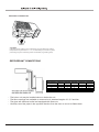
1. To connect the indoor unit to the
outdoor unit use the following electrical
cables.
Electrical connections:
NOTES: The wire color code can be
selected by the installer.
2. Prepare the needed cables for
electrical connection.
3. Connect the cable ends to the
terminals of the indoor and outdoor
units.
4. Secure the multiple wire power cable
with the cable clamps.
The temperature of refrigerant
circuit will be high, please keep
the interconnection cable away
from the copper tube.
1
Power supply 9K 12K 18K
24K 30K 36K (1 PH)
'HVF . ..3+ .3+
ķ
3RZHU&DEOH2'8 [PP [ PP [PP
ĸ
3RZHU&DEOH,'8
Ĺ
&RPPXQLFDWLRQ
[PP
[PP
Power supply 36K (3PH)
42K 48K
ENGLISH

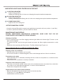
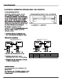
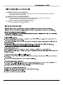
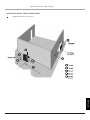
A) HEATING INDICATOR
Lights during operation.
Heating and filtering the air in the room. Keeping the required ambient temperature.
B) COOLING INDICATOR
Lights during operation.
Cooling, humidifying and filtering the air in the room. keeping the required ambient temperature.
C) POWER INDICATOR
Lights as the unit is energised.
INDICATOR LIGHTS AND CONTROLS ON THE UNIT
1
Cleaning of air filter
Your air conditioner has an air filter clogging indicator light. When this indicator light F comes on, the
filter must be cleaned.
- To remove the filter, pull the inlet grid forward and press the filters slightly downwards to unclip
them.
- Reset the unit by pressing the Reset button. The filter indicator light F goes out.
Do not operate the air conditioner without the filter !
Cleaning of the air conditioner
- Rub the inside of the unit with a soft, dry cloth.
- Do not use hot water or volatile detergents, which could damage the face of the air conditioner.
Precautions to be taken
- Check that there are no obstacles preventing the flow of inlet air and pulsed air, on both the indoor
and outdoor units.
- Check that the air conditioner is correctly connected.
Protection of the electronic system
- The indoor unit and the remote control must not be located less than one metre from a television
set, a radio or any other electrical appliance, in order to avoid interference.
- Protect the unit against direct sunlight.
Replacement of the remote control batteries
- Remove the batteries from the remote control unit via the rear flap.
- Fit two new 1.5 V type AAA dry cell batteries.
- Used batteries must be recycled.
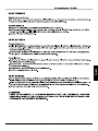
ACTIVE CHARCOAL FILTER
- An active charcoal filter and its support are supplied as accessories with your product. (1 per filter)
- in order to optimise air filtration, you can install it as follows.
MAINTENANCE AND REPAIR
BEFORE UNDERTAKING MAINTENANCE OPERATIONS, MAKE SURE THAT THE AIR
CONDITIONER IS DISCONNECTED FROM THE MAINS.

SERVICING
Routine servicing
- To ensure the correct operation of the installation, it is necessary to have preventive maintenance
of the indoor and outdoor units carried out by qualified personnel.
General installation
- Carry out a visual inspection of the complete installation in service.
- Check the general cleanness of the installation, and check that the condensate evacuations are
not blocked, particularly on the indoor unit, before the summer season.
- Check the condition of the tray.
OUTDOOR UNIT
Coolant system
- Clean the heat exchanger using a special product for aluminium-copper heat exchangers, and
rinse with water. Do not use hot water or steam, as this could cause the pressure of the coolant to
increase.
- Check that the surface of the aluminium fins of the heat exchanger is not damaged by impacts or
scratches, and clean with an appropriate tool if necessary.
Electrical section
- Check that the main power supply cable is not damaged or altered in such a way as to affect the
insulation.
- Check that the interconnecting cables between the two units are not damaged or altered, and that
they are correctly connected.
- Check the earth connection.
INDOOR UNIT
- In order for the installation to operate correctly, it is essential to regularly clean the air filter located
in the intake of the indoor unit.
- When clogged, the filter reduces the air flow through the heat exchanger of the indoor unit, which
in turn reduces the efficiency of the installation and inhibits the cooling of the fan motor.
- Check the cleanness of the indoor heat exchanger.
CAUTION
BEFORE CARRYING OUT ANY OPERATION ON THE EQUIPMENT, CHECK THAT THE
ELECTRICAL POWER SUPPLY IS SWITCHED OFF AND THAT IT CANNOT BE SWITCHED ON
INADVERTENTLY.
ENGLISH


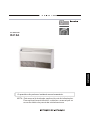
GB
Comfort Range
DC INVERTER
R410A
DEUTSCH

FP

DEUTSCH

11
13
15
Strona jest ładowana ...
Strona jest ładowana ...
Strona jest ładowana ...
Strona jest ładowana ...
Strona jest ładowana ...
Strona jest ładowana ...
Strona jest ładowana ...
Strona jest ładowana ...
Strona jest ładowana ...
Strona jest ładowana ...
Strona jest ładowana ...
Strona jest ładowana ...
Strona jest ładowana ...
Strona jest ładowana ...
Strona jest ładowana ...
Strona jest ładowana ...
Strona jest ładowana ...
Strona jest ładowana ...
Strona jest ładowana ...
Strona jest ładowana ...
Strona jest ładowana ...
Strona jest ładowana ...
Strona jest ładowana ...
Strona jest ładowana ...
Strona jest ładowana ...
Strona jest ładowana ...
Strona jest ładowana ...
Strona jest ładowana ...
Strona jest ładowana ...
Strona jest ładowana ...
Strona jest ładowana ...
Strona jest ładowana ...
Strona jest ładowana ...
Strona jest ładowana ...
Strona jest ładowana ...
Strona jest ładowana ...
Strona jest ładowana ...
Strona jest ładowana ...
Strona jest ładowana ...
Strona jest ładowana ...
Strona jest ładowana ...
Strona jest ładowana ...
Strona jest ładowana ...
Strona jest ładowana ...
Strona jest ładowana ...
Strona jest ładowana ...
Strona jest ładowana ...
Strona jest ładowana ...
Strona jest ładowana ...
Strona jest ładowana ...
Strona jest ładowana ...
Strona jest ładowana ...
Strona jest ładowana ...
Strona jest ładowana ...
Strona jest ładowana ...
Strona jest ładowana ...
Strona jest ładowana ...
Strona jest ładowana ...
Strona jest ładowana ...
Strona jest ładowana ...
Strona jest ładowana ...
Strona jest ładowana ...
Strona jest ładowana ...
Strona jest ładowana ...
Strona jest ładowana ...
Strona jest ładowana ...
Strona jest ładowana ...
Strona jest ładowana ...
Strona jest ładowana ...
Strona jest ładowana ...
Strona jest ładowana ...
Strona jest ładowana ...
Strona jest ładowana ...
Strona jest ładowana ...
Strona jest ładowana ...
Strona jest ładowana ...
Strona jest ładowana ...
Strona jest ładowana ...
Strona jest ładowana ...
Strona jest ładowana ...
Strona jest ładowana ...
Strona jest ładowana ...
Strona jest ładowana ...
Strona jest ładowana ...
Strona jest ładowana ...
Strona jest ładowana ...
Strona jest ładowana ...
Strona jest ładowana ...
Strona jest ładowana ...
Strona jest ładowana ...
Strona jest ładowana ...
Strona jest ładowana ...
Strona jest ładowana ...
Strona jest ładowana ...
Strona jest ładowana ...
Strona jest ładowana ...
Strona jest ładowana ...
Strona jest ładowana ...
Strona jest ładowana ...
Strona jest ładowana ...
Strona jest ładowana ...
Strona jest ładowana ...
Strona jest ładowana ...
Strona jest ładowana ...
Strona jest ładowana ...
Strona jest ładowana ...
Strona jest ładowana ...
Strona jest ładowana ...
-
 1
1
-
 2
2
-
 3
3
-
 4
4
-
 5
5
-
 6
6
-
 7
7
-
 8
8
-
 9
9
-
 10
10
-
 11
11
-
 12
12
-
 13
13
-
 14
14
-
 15
15
-
 16
16
-
 17
17
-
 18
18
-
 19
19
-
 20
20
-
 21
21
-
 22
22
-
 23
23
-
 24
24
-
 25
25
-
 26
26
-
 27
27
-
 28
28
-
 29
29
-
 30
30
-
 31
31
-
 32
32
-
 33
33
-
 34
34
-
 35
35
-
 36
36
-
 37
37
-
 38
38
-
 39
39
-
 40
40
-
 41
41
-
 42
42
-
 43
43
-
 44
44
-
 45
45
-
 46
46
-
 47
47
-
 48
48
-
 49
49
-
 50
50
-
 51
51
-
 52
52
-
 53
53
-
 54
54
-
 55
55
-
 56
56
-
 57
57
-
 58
58
-
 59
59
-
 60
60
-
 61
61
-
 62
62
-
 63
63
-
 64
64
-
 65
65
-
 66
66
-
 67
67
-
 68
68
-
 69
69
-
 70
70
-
 71
71
-
 72
72
-
 73
73
-
 74
74
-
 75
75
-
 76
76
-
 77
77
-
 78
78
-
 79
79
-
 80
80
-
 81
81
-
 82
82
-
 83
83
-
 84
84
-
 85
85
-
 86
86
-
 87
87
-
 88
88
-
 89
89
-
 90
90
-
 91
91
-
 92
92
-
 93
93
-
 94
94
-
 95
95
-
 96
96
-
 97
97
-
 98
98
-
 99
99
-
 100
100
-
 101
101
-
 102
102
-
 103
103
-
 104
104
-
 105
105
-
 106
106
-
 107
107
-
 108
108
-
 109
109
-
 110
110
-
 111
111
-
 112
112
-
 113
113
-
 114
114
-
 115
115
-
 116
116
-
 117
117
-
 118
118
-
 119
119
-
 120
120
-
 121
121
-
 122
122
-
 123
123
-
 124
124
-
 125
125
-
 126
126
-
 127
127
-
 128
128


Airwell 30K Installation Instructions Manual
- Kategoria
- Klimatyzatory typu split
- Typ
- Installation Instructions Manual
- Ten podręcznik jest również odpowiedni dla
w innych językach
- italiano: Airwell 30K
- Deutsch: Airwell 30K
- português: Airwell 30K
- English: Airwell 30K
Inne dokumenty
-
VESTEL VFHS5050 Instrukcja obsługi
-
Sharp AE-A12NR Instrukcja obsługi
-
LG LZ-H200GBA2 Instrukcja obsługi
-
LG UV18FH Instrukcja obsługi
-
Haier HTF-452DM7 Instrukcja obsługi
-
AEG KRC 4344 Instrukcja obsługi
-
Yamaha ESB-1080 Instrukcja obsługi
-
Philips Nina cappuccino Instrukcja obsługi
-
Siemens VSZ2B112/01 Instrukcja obsługi
-
Bosch MSM6B100 Instrukcja obsługi