
(drywall)
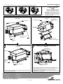
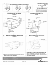
Removing fixture head from housing
Drywall bracket
(4x)
Pan head screw
#8-32 x3/8"
assembly
Housing
Fixture head
with mounting plate
Visor and Non-Visor
Do not
Warning
: Before starting any work ensure
that all sources of power are turned off. All
work must meet local/national codes and be
performed by a certified electrician.
mount fixtures vertically.
Installation Instructions
Vault
C-Scroll
Roundel
These installation instructions are valid with the above Ametrix styles.
Sheet 1 of 5
Large, INDOOR
SRR
(Semi-Recessed, Remote ballast)
ADY071461 REV A (ECN070344)
Pan head screws
#10-32 x5/8"
Store fixture in safe place.
1.
Loosen all #10-32 x5/8" Pan head screws in keyhole slots
inside of fixture housing. (16 1/2" & 22 1/2" fixture sizes use
four(4) screws, 30 1/2 fixture sizes use six(6) screws"
2.
Slide fixture head assembly to side and remove from housing.
3.
1.
Semi-recessed fixtures shown without thermal protectors
#8-32
(4x)
Removing brackets from fixture housing
(2x)
Cover plate
Universal bracket
Hex nut
(ceiling grid)
Thermal protector
cover plate
Exploded view and part call-out
(ceiling grid)
Exploded view and part call-out
(drywall)
all four #10-32 Hex nuts.
Pem-stud
Hex nut
#8-32
(4x)
Universal bracket
(2x)
1.
Remove universal brackets from fixture housing by removing
1.

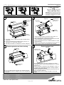
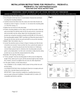
Replacing fixture head
(drywall)
1/4-20 x1 1/2"
Pan head screw
Warning
: Before starting any work ensure
that all sources of power are turned off. All
work must meet local/national codes and be
performed by a certified electrician.
Do not
mount fixtures vertically.
Installation Instructions
Vault w/ visor C-Scroll w/ visor Roundel w/ visor
These installation instructions are valid with the above Ametrix styles.
2.
3.
Sheet 2 of 5
Large, INDOOR
SRR
(Semi-Recessed, Remote ballast)
Visor and Non-Visor
ADY071461 REV A(ECN070344)
2.
3.
Conduit from
power source.
(by others)
Electrical
cover plate
Fixture
housing
1.
Using cut out dimensions provided on page four(4), cut
hole into dry wall and feed power wire to hole.
2.
After removing fixture head, loosen #10-32 x3/8" Pan head
screws and remove electrical cover plate.
3.
Knock out appropriate hole for conduit and attach as shown
on page three(3).
4.
Replace cover plate and secure with #10-32 x3/8" Pan head
screws and press fixture housing into hole in drywall.
1.
Prior to pushing fixture into hole in drywall, tie off fixture
housing to structure using safety wire(by others) as show on
page three(3).
2.
Gently push fixture housing into hole and tighten 1/4-20 x 1
1/2" Pan head screw from inside fixture housing to tighten
drywall bracket around drywall.
3.
Connect appropriate wires from fixture head and ensure all
wires are properly matched.
4.
Replace fixture head assembly on keyhole screws and
tighten.
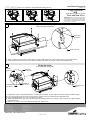
Replacing brackets on fixture housing
1.
Loosely reattach brackets to both sides of fixture housing.
2.
Press brackets flush to ceiling tile and secure using #10-32
Hex nuts.
#8-32
hex nut
(x4)
Ceiling grid
bracket
#8-32
Hex nut
(4x)
Ceiling grid
bracket
Fixture
assembly
1.
If possible, remove ceiling tile from grid to facilitate fixture
installation.
2.
Using cut out dimensions provided on page four(4), cut
appropriate size opening in ceiling tile.
3.
Carefully insert fixture assembly into cut out in ceiling tile.
Securing fixture to ceiling tile
Semi-recessed fixtures shown without thermal protectors
Wiring the fixture
(drywall)

Thermal cover
plate
1.
If applicable,
replace ceiling tile with fixture secured back into ceiling. Remove adjacent tile from ceiling to facilitate wiring.
2.
Loosen #10-32 x3/8" Pan head screws and remove electrical cover plate and knock out appropriate hole.
3.
Using conduit fitting and nut, secure conduit to cover plate.
4.
Attach appropriate wires and ensure all connections are properly matched. If ordered, remove thermal cover plate and wire
thermal protector.
5.
Replace cover plates and secure with #10-32 x3/8" Pan head screws.
Warning
: Before starting any work ensure
that all sources of power are turned off. All
work must meet local/national codes and be
performed by a certified electrician.
Do not
mount fixtures vertically.
Installation Instructions
Vault w/ visor C-Scroll w/ visor Roundel w/ visor
These installation instructions are valid with the above Ametrix styles.
4.
5.
Sheet 3 of 5
Large, INDOOR
SRR
(Semi-Recessed, Remote ballast)
Visor and Non-Visor
ADY071461 REV A(ECN070344)
Wiring the fixture
(both ceiling grid and drywall)
Semi-recessed fixtures shown without thermal protectors
Electrical
cover plate
Conduit nut
(by others)
Conduit fitting
(by others)
Conduit
(by others)
Safety wire
(by others)
Fixture housing
Securing the fixtures with safety wire
(both ceiling grid and drywall)
1.
After securing fixture housing to ceiling structure using provided brackets, reinforce fixture using safety wire(by others).
2.
Using all four tabs located on corners of fixture housing, tie off fixture to structure using safety wire(by others).

Installation Instructions
Vault w/ visor
C-Scroll w/ visor
Roundel w/ visor
These installation instructions are valid with the above Ametrix styles
Warning
: Before starting any work ensure
that all sources of power are turned off. All
work must meet local/national codes and be
performed by a certified electrician.
Do not
mount fixtures vertically.
Large, INDOOR
SRR
(Semi-Recessed, Remote ballast)
Visor and Non-Visor
Sheet 4 of 5
ADY071461 REV A(ECN070344)
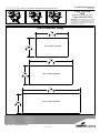
Cutout Dimensions In[mm]
5
828.68
8
32 "
10
7
16
"
265.11
22 1/2" Fixture head size
30 1/2" Fixture head size
5
625.48
8
24 "
10
7
16
"
265.11
16 1/2" Fixture head size
5
473.08
8
18 "
10
7
16
"
265.11
Semi-recessed fixtures shown without thermal protectors

Installation Instructions
Vault w/ visor
C-Scroll w/ visor
Roundel w/ visor
These installation instructions are valid with the above Ametrix styles
Warning
: Before starting any work ensure
that all sources of power are turned off. All
work must meet local/national codes and be
performed by a certified electrician.
Do not
mount fixtures vertically.
Large, INDOOR
SRR
(Semi-Recessed, Remote ballast)
Visor and Non-Visor
Sheet 5 of 5
ADY071461 REV A(ECN070344)
Semi-recessed fixtures shown without thermal protectors
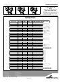
Lamping Size Chart
(lamps provided by others)
FIXTURE SIZE
(inches/ mm) WATTAGE
# OF
LAMPS LAMP TYPE LAMP DESCRIPTION
Lamp
(not to scale)
16
1/2
/ 419.1 32 W 1 T4 Compact Flourescent
16
1/2
/ 419.1 42 W 1 T4 Compact Flourescent
16
1/2
/ 419.1 57 W 1 T4 Compact Flourescent
16
1/2
/ 419.1 100 W 1 ED17 Ceramic Metal Halide
16
1/2
/ 419.1 150 W 1 T6 Ceramic Metal Halide
16
1/2
/ 419.1 175 W 1 ED17 Ceramic Metal Halide
22
1/2
/571.5 mm 250 W 1 ET18 Metal Halide
22
1/2
/571.5 mm 400 W 1 ET18 Metal Halide
22
1/2
/571.5 mm 150 W 2 T6 Ceramic Metal Halide
22
1/2
/571.5 mm 32 W 2 T4 Compact Flourescent
22
1/2
/571.5 mm 42 W 2 T4 Compact Flourescent
22
1/2
/571.5 mm 250 W 1 ET18 Metal Halide
22
1/2
/571.5 mm 400 W 1 ET18 Metal Halide
22
1/2
/571.5 mm 150 W 2 T6 Ceramic Metal Halide
22
1/2
/571.5 mm 350 W 1 T3 Halogen(Double Ended)
22
1/2
/571.5 mm 500 W 1 T3 Halogen(Double Ended)
30
1/2
/ 774.7 36 W 1 T5 Twin Tube
30
1/2
/ 774.7 40 W 1 T5 Twin Tube
30
1/2
/ 774.7 50 W 1 T5 Twin Tube
30
1/2
/ 774.7 55 W 1 T5 Twin Tube
30
1/2
/ 774.7 36 W 2 T5 Twin Tube
30
1/2
/ 774.7 40 W 2 T5 Twin Tube
30
1/2
/ 774.7 50 W 2 T5 Twin Tube
30
1/2
/ 774.7 55 W 2 T5 Twin Tube
30
1/2
/ 774.7 250 W 2 ET18 Metal Halide
30
1/2
/ 774.7 400 W 2 ET18 Metal Halide
30
1/2
/ 774.7 900 W 1 T3 Halogen(Double Ended)
30
1/2
/ 774.7 1000 W 1 T3 Halogen(Double Ended)
-
 1
1
-
 2
2
-
 3
3
-
 4
4
-
 5
5


w innych językach
- English: Ametrix SRR Installation guide
Powiązane artykuły

Inne dokumenty
-
Unbranded 72171-189-L Instrukcja obsługi
-
Lightolier 40600N2 Instrukcja obsługi
-
Williams AX2 LED Series Instrukcja instalacji
-
Strasser 51.924 Instrukcja instalacji
-
Legrand Wiremold CDBK-50 Karta katalogowa
-
 George Kovacs P8239-671-L Instrukcja obsługi
-
Samsung SI-L8T23112CEU Skrócona instrukcja obsługi
