Wren Kitchens 2070 & 2250mm Walk-in Tower Unit Assembly Guide
- Typ
- Assembly Guide

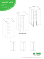
TOWER UNIT
2070 & 2250
Walk in
Assembly Guide
For Internal Use: FI.WR.INS.014_WKIN0062_WalkIn_TowerGuide_Rev12.indd
2070 - 2250 x600
1 Door
50/50 Door
70/30 Door

TOWER UNIT
2070 & 2250
Walk in
Assembly Guide
For Internal Use: FI.WR.INS.014_WKIN0062_WalkIn_TowerGuide_Rev12.inddPage 1
BEFORE YOU START
INSTALLATION
SHOULD BE
PERFORMED BY A
COMPETENT
PERSON ONLY.
THIS PRODUCT COULD
BE DANGEROUS
IF INCORRECTLY
INSTALLED
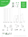
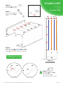
Panel A
x1 End Panel
Left Hand
Panel B
x1 End Panel
Right Hand
Panel C
x1 Back Panel
Left Hand
Panel D
x1 Back Panel
Right Hand
Panel sE
x1 Top Panel
Panel sM
x4 Fixed Shelf
Frontals
50/50 or 1Dr or 70/30
(Packed Seperately)
Plinth
x1
L Bracket (LGE)
x4
Fixing Plate (U)
x4
Hinge Mounting Plate
Inc Screws
Hinge
Inc Screws
(F) x40
Wooden Dowel
(H) x20
Cam lock
NOT to be
used with
CAM DOWEL
& CAM LOCK
(K) x36 45mm Screws (L) x12 15mm Screws
REQUIRED TOOLS
70/30 OPTION
1Dr OPTION
50/50 OPTION
(M) x8
Cover Cap
(Per Colour)
(W) x20
Cam Dowel

TOWER UNIT
2070 & 2250
Walk in
Assembly Guide
For Internal Use: FI.WR.INS.014_WKIN0062_WalkIn_TowerGuide_Rev12.indd Page 2
F
F
W
W
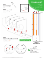
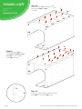
Seat (W)
cam dowel
into hole as
shown.
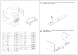
Step 2.
Seat dowel (F) into
holes in end panel (A)
as shown.
Step 1.
Seat cam dowel (W) into
holes in end panel (A) as
shown.
sM
sM
sM
sM
sE
A
Step 4.
Join panels (sE) and (sM) to end
panel (A).
Insert cam locks (H).
Do NOT tighten until Step 7.
Do not use power tools with
cam dowel (G) or cam lock (H)
Step 3.
Attach panels (sM) and (sE) to end panel (A),
using cam dowel (W) (in blue) and also using
dowels (F) (in orange)
in positions as shown.
sM
sM
A
View from underside View from underside
A
H
H
A
LH
from top
from bottom
DOWEL (F)
& CAM DOWEL (W)
LOCATION DETAIL
W
F
W
LH

TOWER UNIT
2070 & 2250
Walk in
Assembly Guide
For Internal Use: FI.WR.INS.014_WKIN0062_WalkIn_TowerGuide_Rev12.inddPage 3
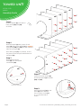
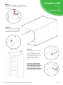
Step 5.
Seat 10x dowels (F) into holes in
both panels (sM) and (sE)
as shown.
sE
K
K
K
K
K
K
K
K
K
K
K
K
K
K
K
F
F
F
F
F
F
F
F
F
F
sM
sM
sM
sM
Step 8.
Using 15 x 45mm screws (K)
secure back panel (C) to panels
(sM) and (sE).
Step 9.
Secure back panel (C) to end
panel (A) at the bottom.
Use 4 x 15mm screws (L)
to 1 x L bracket LGE as
shown.
Step 6.
Slide back panel (C) into groove of end
panel (A). Also insert dowels (F) (in orange)
from panels (sM) and (sE) into the required
holes in back panel (C).
Once back panel (C) is in position, ensure
the panel is ush & square with bottom of
end panel (A).
L
C
L
L
L
A
LH
A
sM
A
View from underside
H
H
Step 7.
Hand tighten all cam
locks (H), this will expand
cam dowels (W).

TOWER UNIT
2070 & 2250
Walk in
Assembly Guide
For Internal Use: FI.WR.INS.014_WKIN0062_WalkIn_TowerGuide_Rev12.indd Page 4
sM
sM
sM
sM
sE
C
Step 10.
Seat dowel (F) into holes in
end panel (B) as shown.
Step 11
Seat cam dowel (W) into
holes in end panel (B) as
shown.
Seat (W)
cam dowel
into hole as
shown.
Do not use power tools with
cam dowel (G) or cam lock (H)
Step 12.
Attach end panel (B) to panels (sM) and (sE)
using cam dowel (W) (in blue) and also using
dowels (F) (in orange) in positions as shown.
FF
RIGHT HAND
B
WW
from bottom
from top
DOWEL (F)
& CAM DOWEL (W)
LOCATION DETAIL
Step 13.
Join panels (sE) and (sM) to
end panel (A).
Insert cam locks (H).
Do NOT tighten until Step 18.
F
W
sM
sM
View from underside
View from underside
B
B
H
B
RH
LH
A
RH

TOWER UNIT
2070 & 2250
Walk in
Assembly Guide
For Internal Use: FI.WR.INS.014_WKIN0062_WalkIn_TowerGuide_Rev12.inddPage 5
Step 14.
Seat 10x dowels (F) into holes in
both panels (sM) and (sE)
as shown.
sM
sM
sM
sM
sE
F
Step 15.
Secure back panel (D) to
panels (sE) and (sM) and back
panel (C). Use 20 x 45mm
screws (K) as shown.
Step 16.
Ensure to insert the lower position of back
panel (D) into end panel (B) groove.
K
A
B
RH
LH
C
D
C
B
RH
LH
B
D

TOWER UNIT
2070 & 2250
Walk in
Assembly Guide
For Internal Use: FI.WR.INS.014_WKIN0062_WalkIn_TowerGuide_Rev12.indd Page 6
Step 17.
Secure back panel (D) to end panel (B) at the
bottom. Use 4 x15mm screws (L) to 1 x L bracket
LGE as shown.
Step 18.
Hand tighten all cam locks (H),
this will expand cam dowels (W)
and tighten the unit together.
D
M
View from underside
B
H
Step 19.
Secure tower to the wall using
L brackets LGE.
Use 2 x 15mm screws (L) to
secure each of the
L brackets LGE to the cabinets
at either side. Then screw
through into the wall as
shown.
Screws for xing to walls
are not provided as these
vary depending on your wall
material and construction.
Ensure appropriate xings for
wall constructions are used.
B
B
BB
L
L

TOWER UNIT
2070
Walk in
Assembly Guide
For Internal Use: FI.WR.INS.014_WKIN0062_WalkIn_TowerGuide_Rev10.inddPage 7
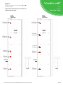
70/30
HINGE
POSITION
50/50 & 1 DOOR
HINGE
POSITION
A or BA or B
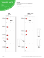
1976mm 1976mm
1236mm
1016mm
996mm
1486mm
776mm
276mm 276mm
1944mm 1944mm
1204mm
984mm
964mm
1454mm
744mm
244mm 244mm
Step 20.
Attach hinge plates onto end panel (A) or (B) to
suit as shown.
Hinge side to be mounted in accordance to
customer kitchen plan.
FrontFront
From TopFrom Top
From BottomFrom Bottom
50/50
70/30
1 Dr
Door
INSIDE
FACE
INSIDE
FACE

TOWER UNIT
2250
Walk in
Assembly Guide
Page 8For Internal Use: FI.WR.INS.014_WKIN0062_WalkIn_TowerGuide_Rev10.indd
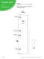
70/30
HINGE
POSITION
50/50
HINGE
POSITION
A or BA or B
2156mm
2156mm
1176mm
1666mm
996mm
1576mm
776mm
276mm
276mm
956mm
2124mm
2124mm
1144mm
1634mm
964mm
1544mm
744mm
244mm
244mm
924mm
Step 20.
Attach hinge plates onto end panel (A) or (B)
to suit as shown.
Hinge side to be mounted in accordance to
customer kitchen plan.
FrontFront
From TopFrom Top
From BottomFrom Bottom
50/50
70/30
INSIDE
FACE
INSIDE
FACE

For Internal Use: FI.WR.INS.014_WKIN0062_WalkIn_TowerGuide_Rev10.indd
TOWER UNIT
2250 1Dr
Walk in
Assembly Guide
1 Door
HINGE
POSITION
2156mm
1351.5mm
1080.5mm
1319.5mm
1048.5mm
276mm
2124mm
244mm
Step 20.
Attach hinge plates onto end panel (A) or (B) to
suit as shown.
Hinge side to be mounted in accordance to
customer kitchen plan.
Front
From Top
From Bottom
1 Dr
Door
A or B
INSIDE
FACE
Page 9

TOWER UNIT
2070 & 2250
Walk in
Assembly Guide
For Internal Use: FI.WR.INS.014_WKIN0062_WalkIn_TowerGuide_Rev12.indd Page 10
TOWER UNIT
2070 & 2250
Walk in
Assembly Guide
U
U
U
U
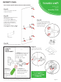
Step 24.
Adjust hinge to suit. As shown below.
View from Inside of Carcase
To adjust hinge using a screw
driver, tighten or loosen as
required at points 1 & 2.
Point 1 - In - Out
Point 2 - Left - Right
1
2
FRONTAL
HINGE
ADJUSTMENT
To release door
pull catch as shown,
doing so will release the
hinge from the hinge
mounting plate.
The top and bottom
hinges MUST be
adjusted to the SAME
STRENGTH.
Hinge Cover Caps
Hinge Plates
Step 25.
Fit cover caps to hinge.
Adjust soft-close to suit.
The Top and Bottom
hinges MUST be
adjusted to the SAME
STRENGTH.
Step 22.
Align doors & frontal plinth to
join together using
4 x xing plates (U) to the
back of both frontals. Ensure
a 3mm gap is maintained
between each frontal once
xed together.
Screw in place using 4 x 15mm
screws (L) per xing plate (U).
See Customer Specic Kitchen Plan For Tower Frontals
Fixing plates
Step 21.
Insert hinge where required
in holes as shown.
Step 23.
Secure hinges by tightening
2 x screws with hinge dowels
attached. These are
already positioned
within the hinges.
INFINITY PLUS
To Move the
hinge up/down,
loosen screws
A + B,
Manoeuvre
the door, then
re-tighten the
screws
A
B

For Internal Use: FI.WR.INS.014_WKIN0062_WalkIn_TowerGuide_Rev11.inddPage 11
TOWER UNIT
2070 & 2250
Walk in
Assembly Guide
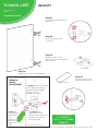
Step 24.
Adjust hinge to suit. As shown below.
Step 22.
Secure hinges with the
2 x screws.
View from Inside of Carcase
1
2
FRONTAL
HINGE
ADJUSTMENT
Hinge Cover Caps
Step 25.
Fit cover caps to hinge.
Adjust Softclose to suit.
The Top and Bottom
hinges MUST be
adjusted to the SAME
STRENGTH.
Hinge Plates
Step 23.
Attach the door to unit,
clip hinge onto hinge plate and
click to secure.
Step 21.
Insert hinge into hinge holes
provided.
To adjust hinge using a screw
driver, tighten or loosen as
required at points 1 & 2.
Point 1 - In - Out
Point 2 - Left - Right
To release door
pull catch as shown,
doing so will release the
hinge from the hinge
mounting plate.
INFINITY
To Move the
hinge up/down,
loosen screws
A + B,
Manoeuvre
the door, then
re-tighten the
screws
A
B
-
 1
1
-
 2
2
-
 3
3
-
 4
4
-
 5
5
-
 6
6
-
 7
7
-
 8
8
-
 9
9
-
 10
10
-
 11
11
-
 12
12


Wren Kitchens 2070 & 2250mm Walk-in Tower Unit Assembly Guide
- Typ
- Assembly Guide
w innych językach
Inne dokumenty
-
Luxor LOTM Instrukcja obsługi
-
 Baxton Studio 30553312 Assembly Instructions
-
Atlantic Venus 198CD Assembly Instruction
-
FUFU GAGA LJY-WFKF210049-01 3-Tiered Shoe Storage Instrukcja instalacji
-
Sea Ray 2005 200SD Parts Manual
-
-
-
-
-
