Allen-Bradley Compact I/O 5069 series Installation Instructions Manual
- Typ
- Installation Instructions Manual

Installation Instructions
Original Instructions
5069 Compact I/O EtherNet/IP Adapters
Catalog Numbers 5069-AENTR, 5069-AEN2TR
The 5069 Compact I/O™ EtherNet/IP adapters perform the following functions:
• Facilitate high-speed data transfer across an EtherNet/IP network between 5069 Compact I/O modules and a Logix5000™ controller
• Provide system-side and field-side power to 5069 Compact I/O modules
• Support as many as thirty-one 5069 Compact I/O modules
The adapters are configured with the Studio 5000 Logix Designer® application. For more information on how to use 5069 Compact I/O
EtherNet/IP adapters, including the compatible Logix5000 controllers and Logix Designer application versions, see the publications that are listed
in
Additional Resources on page 19.
Summary of Changes
This publication was revised to include information about the 5069-AENTR adapter.
Topic Page
Summary of Changes 1
About the Adapters 5
Install a 5069 Compact I/O System 6
Set the Network Internet Protocol (IP) Address 8
Install the Adapter onto the DIN Rail 9
Connect Power to the 5069-AEN2TR Adapter 9
Connect Power to the 5069-AENTR Adapter 13
Connect the Adapter to an EtherNet/IP Network 16
Install the End Cap 16
Power the System 16
Remove or Replace the Adapter 17
Specifications 18
Additional Resources 19

2 Rockwell Automation Publication 5069-IN003C-EN-P - December 2016
5069 Compact I/O EtherNet/IP Adapters
ATTENTION: Read this document and the documents listed in the Additional Resources section about installation, configuration and operation of this equipment before you install, configure, operate or
maintain this product. Users are required to familiarize themselves with installation and wiring instructions in addition to requirements of all applicable codes, laws, and standards.
Activities including installation, adjustments, putting into service, use, assembly, disassembly, and maintenance are required to be carried out by suitably trained personnel in accordance with applicable code
of practice.
If this equipment is used in a manner not specified by the manufacturer, the protection provided by the equipment may be impaired.
⌘˖൘ᆹ㻵ǃ䝽㖞ǃ઼㔤ᣔᵜӗ૱ࡽˈ䈧䰵䈫ᵜ᮷ẓԕ৺ Ā ަԆ䍴Ⓚ ā 䜘࠶ࡇࠪⲴᴹޣ䇮༷ᆹ㻵ǃ䝽㖞઼Ⲵᓄ᮷ẓDŽ䲔Ҷᡰᴹ䘲⭘㿴㤳ǃ⌅
ᖻ઼ḷ߶Ⲵޣ㾱≲ѻཆˈ⭘ᡧ䘈ᗵ享⟏ᚹᆹ㻵઼᧕㓯䈤᰾DŽ
ᆹ㻵ǃ䈳ᮤǃᣅ䘀ǃ֯⭘ǃ㓴㻵ǃন઼㔤ᣔㅹ亩ᗵ享⭡㓿䗷䘲ᖃ䇝㓳ⲴуъӪઈ᤹➗䘲⭘Ⲵ㿴㤳ᇎᯭDŽ
ྲ᷌ᵚ᤹➗ࡦ䙐୶ᤷᇊⲴᯩᔿ֯⭘䈕䇮༷ˈࡉਟ㜭Պᦏᇣ䇮༷ᨀⲴ؍ᣔDŽ
ATENCIÓN: Antes de instalar, configurar, poner en funcionamiento o realizar el mantenimiento de este producto, lea este documento y los documentos listados en la sección Recursos adicionales acerca de la
instalación, configuración y operación de este equipo. Los usuarios deben familiarizarse con las instrucciones de instalación y cableado y con los requisitos de todos los códigos, leyes y estándares vigentes.
El personal debidamente capacitado debe realizar las actividades relacionadas a la instalación, ajustes, puesta en servicio, uso, ensamblaje, desensamblaje y mantenimiento de conformidad con el código de
práctica aplicable.
Si este equipo se usa de una manera no especificada por el fabricante, la protección provista por el equipo puede resultar afectada.
ATENÇÃO: Leia este e os demais documentos sobre instalação, configuração e operação do equipamento que estão na seção Recursos adicionais antes de instalar, configurar, operar ou manter este produto. Os
usuários devem se familiarizar com as instruções de instalação e fiação além das especificações para todos os códigos, leis e normas aplicáveis.
É necessário que as atividades, incluindo instalação, ajustes, colocação em serviço, utilização, montagem, desmontagem e manutenção sejam realizadas por pessoal qualificado e especializado, de acordo com o
código de prática aplicável.
Caso este equipamento seja utilizado de maneira não estabelecida pelo fabricante, a proteção fornecida pelo equipamento pode ficar prejudicada.
ВНИМАНИЕ: Перед тем как устанавливать, настраивать, эксплуатировать или обслуживать данное оборудование, прочитайте этот документ и документы, перечисленные в разделе
«Дополнительные ресурсы». В этих документах изложены сведения об установке, настройке и эксплуатации данного оборудования. Пользователи обязаны ознакомиться с инструкциями по
установке и прокладке соединений, а также с требованиями всех применимых норм, законов и стандартов.
Все действия, включая установку, наладку, ввод в эксплуатацию, использование, сборку, разборку и техническое обслуживание, должны выполняться обученным персоналом в соответствии с
применимыми нормами и правилами.
Если оборудование используется не предусмотренным производителем образом, защита оборудования может быть нарушена.
ὀព ᮏ〇ရࢆタ⨨ࠊᵓᡂࠊ✌ືࡲࡓࡣಖᏲࡍࡿ๓ࠊᮏ᭩࠾ࡼࡧᮏᶵჾࡢタ⨨ࠊタᐃࠊ᧯సࡘ࠸࡚ࡢཧ⪃㈨ᩱࡢヱᙜ⟠ᡤグ㍕ࡉࢀ࡚࠸ࡿᩥ᭩┠
ࢆ㏻ࡋ࡚ࡃࡔࡉ࠸ࠋ࣮ࣘࢨࡣࠊࡍ࡚ࡢヱᙜࡍࡿ᮲ࠊἲᚊࠊつ᱁ࡢせ௳ຍ࠼࡚ࠊタ⨨࠾ࡼࡧ㓄⥺ࡢᡭ㡰⩦⇍ࡋ࡚࠸ࡿᚲせࡀ࠶ࡾࡲࡍࠋ
タ⨨ㄪᩚࠊ㐠㌿ࡢ㛤ጞࠊ⏝ࠊ⤌❧࡚ࠊゎయࠊಖᏲࢆྵࡴㅖసᴗࡣࠊヱᙜࡍࡿᐇつ๎ᚑࡗ࡚カ⦎ࢆཷࡅࡓ㐺ษ࡞సᴗဨࡀᐇ⾜ࡍࡿᚲせࡀ࠶ࡾࡲࡍࠋ
ᮏᶵჾࡀ〇㐀࣓࣮࢝ࡼࡾᣦᐃࡉࢀ࡚࠸࡞࠸᪉ἲ࡛⏝ࡉࢀ࡚࠸ࡿሙྜࠊᶵჾࡼࡾᥦ౪ࡉࢀ࡚࠸ࡿಖㆤࡀᦆ࡞ࢃࢀࡿᜍࢀࡀ࠶ࡾࡲࡍࠋ
ACHTUNG: Lesen Sie dieses Dokument und die im Abschnitt „Weitere Informationen“aufgeführten Dokumente, die Informationen zu Installation, Konfiguration und Bedienung dieses Produkts enthalten,
bevor Sie dieses Produkt installieren, konfigurieren, bedienen oder warten. Anwender müssen sich neben den Bestimmungen aller anwendbaren Vorschriften, Gesetze und Normen zusätzlich mit den
Installations- und Verdrahtungsanweisungen vertraut machen.
Arbeiten im Rahmen der Installation, Anpassung, Inbetriebnahme, Verwendung, Montage, Demontage oder Instandhaltung dürfen nur durch ausreichend geschulte Mitarbeiter und in Übereinstimmung mit
den anwendbaren Ausführungsvorschriften vorgenommen werden.
Wenn das Gerät in einer Weise verwendet wird, die vom Hersteller nicht vorgesehen ist, kann die Schutzfunktion beeinträchtigt sein.
ATTENTION : Lisez ce document et les documents listés dans la section Ressources complémentaires relatifs à l’installation, la configuration et le fonctionnement de cet équipement avant d’installer,
configurer, utiliser ou entretenir ce produit. Les utilisateurs doivent se familiariser avec les instructions d’installation et de câblage en plus des exigences relatives aux codes, lois et normes en vigueur.
Les activités relatives à l’installation, le réglage, la mise en service, l’utilisation, l’assemblage, le démontage et l’entretien doivent être réalisées par des personnes formées selon le code de pratique en vigueur.
Si cet équipement est utilisé d’une façon qui n’a pas été définie par le fabricant, la protection fournie par l’équipement peut être compromise.
㭒㦮 a ⽎G㩲䛞G㍺䂮 SG㍺㩫 SG㧧☯G⡦⓪G㥶㰖G⽊㑮䞮₆G㩚㠦G⽎Gⶎ㍲⯒G䙂䞾䞮㡂G㍺䂮 SG㍺㩫GG㧧☯㠦Gὖ䞲G㺎ἶG㧦⬢G㎏㎮㦮Gⶎ㍲✺㦚G✲㔲G㧓ἶG㑯㰖䞮
㕃㔲㡺 UG㌂㣿㧦⓪G⳾✶Gὖ⩾G′㩫 SG⻫′GG䚲㭖㠦㍲G㣪ῂ䞮⓪G㌂䟃㠦G╖䟊G✲㔲G㍺䂮GG⺆㍶G㰖䂾㦚G㑯㰖䟊㟒G䞿┞┺ U
㍺䂮 SG㫆㩫 SGṖ☯ SG㌂㣿 SG㫆Ⱃ SG䟊 SG㥶㰖⽊㑮G❇G⳾✶G㧧㠛㦖Gὖ⩾G′㩫㠦G➆⧒G㩗㩞䞲Gᾦ㥷㦚G㦖G㌂㣿㧦⯒G䐋䟊㍲ⰢG㑮䟟䟊㟒G䞿┞┺ U
⽎G㧻゚⯒G㩲㫆㌂ṖGⳛ㔲䞮㰖G㞠㦖G⻫㦒⪲G㌂㣿䞮ⳊG㧻゚㦮G⽊䢎G₆⓻㧊G㏦㌗♶G㑮G㧞㔋┞┺ U
ATTENZIONE Prima di installare, configurare ed utilizzare il prodotto, o effettuare interventi di manutenzione su di esso, leggere il presente documento ed i documenti elencati nella sezione “Altre risorse”,
riguardanti l’installazione, la configurazione ed il funzionamento dell’apparecchiatura. Gli utenti devono leggere e comprendere le istruzioni di installazione e cablaggio, oltre ai requisiti previsti dalle leggi,
codici e standard applicabili.
Le attività come installazione, regolazioni, utilizzo, assemblaggio, disassemblaggio e manutenzione devono essere svolte da personale adeguatamente addestrato, nel rispetto delle procedure previste.
Qualora l’apparecchio venga utilizzato con modalità diverse da quanto previsto dal produttore, la sua funzione di protezione potrebbe venire compromessa.
DİKKAT: Bu ürünün kurulumu, yapılandırılması, işletilmesi veya bakımı öncesinde bu dokümanı ve bu ekipmanın kurulumu, yapılandırılması ve işletimi ile ilgili İlave Kaynaklar bölümünde yer listelenmiş
dokümanları okuyun. Kullanıcılar yürürlükteki tüm yönetmelikler, yasalar ve standartların gereksinimlerine ek olarak kurulum ve kablolama talimatlarını da öğrenmek zorundadır.
Kurulum, ayarlama, hizmete alma, kullanma, parçaları birleştirme, parçaları sökme ve bakım gibi aktiviteler sadece uygun eğitimleri almış kişiler tarafından yürürlükteki uygulama yönetmeliklerine uygun
şekilde yapılabilir.
Bu ekipman üretici tarafından belirlenmiş amacın dışında kullanılırsa, ekipman tarafından sağlanan koruma bozulabilir.
⌘һ丵˖൘ᆹ㼍ǃ䁝ᇊǃᡆ㏝䆧ᵜ⭒૱ࡽˈ䃻ݸ䯡䆰↔᮷Ԧԕ৺ࡇᯬ NjަԆ䋷Ⓚnjㄐㇰѝᴹ䰌ᆹ㼍ǃ䁝ᇊ㠷↔䁝ۉⲴ᮷ԦDŽ֯⭘㘵ᗵ丸⟏ᚹᆹ㼍
઼䝽㐊ᤷ⽪ˈіㅖਸᡰᴹ⌅㾿ǃ⌅ᖻ઼⁉Ⓠ㾱≲DŽ
वᤜᆹ㼍ǃ䃯ᮤǃӔԈ֯⭘ǃ֯⭘ǃ㍴㼍ǃন઼㏝䆧ㅹअ䜭ᗵ丸Ӕ⭡ᐢ㏃䙾䚙⮦䁃㐤ⲴӪ䙢㹼ˈԕㅖਸ䚙⭘Ⲵሖ⌅㾿DŽ
ྲ᷌ሷ䁝ۉ⭘ᯬ䶎㼭䙐୶ᤷᇊⲴ⭘䙄ᱲˈਟ㜭ᴳ䙐ᡀ䁝ۉᡰᨀⲴ؍䆧࣏㜭ਇᨽDŽ
POZOR: Než začnete instalovat, konfigurovat či provozovat tento výrobek nebo provádět jeho údržbu, přečtěte si tento dokument a dokumenty uvedené v části Dodatečné zdroje ohledně instalace, konfigurace
a provozu tohoto zařízení. Uživatelé se musejí vedle požadavků všech relevantních vyhlášek, zákonů a norem nutně seznámit také s pokyny pro instalaci a elektrické zapojení.
Činnosti zahrnující instalaci, nastavení, uvedení do provozu, užívání, montáž, demontáž a údržbu musí vykonávat vhodně proškolený personál v souladu s příslušnými prováděcími předpisy.
Pokud se toto zařízení používá způsobem neodpovídajícím specifikaci výrobce, může být narušena ochrana, kterou toto zařízení poskytuje.
UWAGA: Przed instalacją, konfiguracją, użytkowaniem lub konserwacją tego produktu należy przeczytać niniejszy dokument oraz wszystkie dokumenty wymienione w sekcji Dodatkowe źródła omawiające
instalację, konfigurację i procedury użytkowania tego urządzenia. Użytkownicy mają obowiązek zapoznać się z instrukcjami dotyczącymi instalacji oraz oprzewodowania, jak również z obowiązującymi
kodeksami, prawem i normami.
Działania obejmujące instalację, regulację, przekazanie do użytkowania, użytkowanie, montaż, demontaż oraz konserwację muszą być wykonywane przez odpowiednio przeszkolony personel zgodnie z
obowiązującym kodeksem postępowania.
Jeśli urządzenie jest użytkowane w sposób inny niż określony przez producenta, zabezpieczenie zapewniane przez urządzenie może zostać ograniczone.
OBS! Läs detta dokument samt dokumentet, som står listat i avsnittet Övriga resurser, om installation, konfigurering och drift av denna utrustning innan du installerar, konfigurerar eller börjar använda eller
utföra underhållsarbete på produkten. Användare måste bekanta sig med instruktioner för installation och kabeldragning, förutom krav enligt gällande koder, lagar och standarder.
Åtgärder som installation, justering, service, användning, montering, demontering och underhållsarbete måste utföras av personal med lämplig utbildning enligt lämpligt bruk.
Om denna utrustning används på ett sätt som inte anges av tillverkaren kan det hända att utrustningens skyddsanordningar försätts ur funktion.
LET OP: Lees dit document en de documenten die genoemd worden in de paragraaf Aanvullende informatie over de installatie, configuratie en bediening van deze apparatuur voordat u dit product installeert,
configureert, bediend of onderhoudt. Gebruikers moeten zich vertrouwd maken met de installatie en de bedradingsinstructies, naast de vereisten van alle toepasselijke regels, wetten en normen.
Activiteiten zoals het installeren, afstellen, in gebruik stellen, gebruiken, monteren, demonteren en het uitvoeren van onderhoud mogen uitsluitend worden uitgevoerd door hiervoor opgeleid personeel en in
overeenstemming met de geldende praktijkregels.
Indien de apparatuur wordt gebruikt op een wijze die niet is gespecificeerd door de fabrikant, dan bestaat het gevaar dat de beveiliging van de apparatuur niet goed werkt.

Rockwell Automation Publication 5069-IN003C-EN-P - December 2016 3
5069 Compact I/O EtherNet/IP Adapters
Environment and Enclosure
ATTENTION: This equipment is intended for use in a Pollution Degree 2 industrial environment, in overvoltage Category II applications (as defined in
EN/IEC 60664-1), at altitudes up to 2000 m (6562 ft) without derating.
This equipment is not intended for use in residential environments and may not provide adequate protection to radio communication services in such
environments.
This equipment is supplied as open-type equipment for indoor use. It must be mounted within an enclosure that is suitably designed for those specific
environmental conditions that will be present and appropriately designed to prevent personal injury resulting from accessibility to live parts. The enclosure must
have suitable flame-retardant properties to prevent or minimize the spread of flame, complying with a flame spread rating of 5VA or be approved for the
application if nonmetallic. The interior of the enclosure must be accessible only by the use of a tool. Subsequent sections of this publication may contain more
information regarding specific enclosure type ratings that are required to comply with certain product safety certifications.
In addition to this publication, see the following:
• Industrial Automation Wiring and Grounding Guidelines, publication
1770-4.1, for more installation requirements.
• NEMA 250 and EN/IEC 60529, as applicable, for explanations of the degrees of protection provided by enclosures.
North American Hazardous Location Approval
The following information applies when operating this equipment in hazardous
locations:
Informations sur l'utilisation de cet équipement en environnements dangereux:
Products marked "CL I, DIV 2, GP A, B, C, D" are suitable for use in Class I Division 2 Groups A, B, C, D,
Hazardous Locations and nonhazardous locations only. Each product is supplied with markings on
the rating nameplate indicating the hazardous location temperature code. When combining
products within a system, the most adverse temperature code (lowest "T" number) may be used to
help determine the overall temperature code of the system. Combinations of equipment in your
system are subject to investigation by the local Authority Having Jurisdiction at the time of
installation.
Les produits marqués "CL I, DIV 2, GP A, B, C, D" ne conviennent qu'à une utilisation en
environnements de Classe I Division 2 Groupes A, B, C, D dangereux et non dangereux. Chaque
produit est livré avec des marquages sur sa plaque d'identification qui indiquent le code de
température pour les environnements dangereux. Lorsque plusieurs produits sont combinés dans
un système, le code de température le plus défavorable (code de température le plus faible) peut
être utilisé pour déterminer le code de température global du système. Les combinaisons
d'équipements dans le système sont sujettes à inspection par les autorités locales qualifiées au
moment de l'installation.
WARNING
EXPLOSION HAZARD
• Do not disconnect equipment unless power has been removed or the area is
known to be nonhazardous.
• Do not disconnect connections to this equipment unless power has been
removed or the area is known to be nonhazardous. Secure any external
connections that mate to this equipment by using screws, sliding latches,
threaded connectors, or other means provided with this product.
• Substitution of components may impair suitability for Class I, Division 2.
• If this product contains batteries, they must be changed only in an area
known to be nonhazardous.
AVERTISSMENT
RISQUE D'EXPLOSION
• Couper le courant ou s'assurer que l'environnement est classé non
dangereux avant de débrancher l'équipement.
• Couper le courant ou s'assurer que l'environnement est classé non
dangereux avant de débrancher les connecteurs. Fixer tous les connecteurs
externes reliés à cet équipement à l'aide de vis, loquets coulissants,
connecteurs filetés ou autres moyens fournis avec ce produit.
• La substitution de composants peut rendre cet équipement inadapté à une
utilisation en environnement de Classe I, Division 2.
• S'assurer que l'environnement est classé non dangereux avant de changer
les piles.
European Hazardous Location Approval
The following applies to products marked , II 3 G.
• Are Equipment Group II, Equipment Category 3, and comply with the Essential Health and Safety Requirements relating to the design and construction of such equipment given in Annex II to
Directive 2014/34/EU. See the EC Declaration of Conformity at http://www.rockwellautomation.com/products/certification for details.
• The type of protection is "Ex nA IIC T4 Gc" according to EN 60079-15.
• The 5069-AEN2TR EtherNet/IP adapter complies to standards: EN 60079-0:2012+A11:2013, EN 60079-15:2010 when used at or below 125V AC, reference certificate number DEMKO 15 ATEX 1455X.
• The 5069-AENTR EtherNet/IP adapter complies to standards: EN 60079-0:2012+A11:2013, EN 60079-15:2010, reference certificate number DEMKO 16 ATEX 1758X.
• Are intended for use in areas in which explosive atmospheres caused by gases, vapors, mists, or air are unlikely to occur, or are likely to occur only infrequently and for short periods. Such locations
correspond to Zone 2 classification according to ATEX directive 1999/92/EC.
IEC Hazardous Location Approval
The following applies to products with IECEx certification: Such modules:
• Are intended for use in areas in which explosive atmospheres caused by gases, vapors, mists, or air are unlikely to occur, or are likely to occur only infrequently and for short periods. Such locations
correspond to Zone 2 classification to IEC 60079-0.
• The type of protection is "Ex nA IIC T4 Gc" according to IEC 60079-15.
• The 5069-AEN2TR EtherNet/IP adapter complies to standards IEC 60079-0:6th Edition, IEC-60079-15:4th Edition when used at or below 125V AC, reference IECEx certificate number
IECEx UL 15.0007X.
• The 5069-AENTR EtherNet/IP adapter complies to standards IEC 60079-0:6th Edition, IEC-60079-15:4th Edition, reference IECEx certificate number IECEx UL 16.0124X.

4 Rockwell Automation Publication 5069-IN003C-EN-P - December 2016
5069 Compact I/O EtherNet/IP Adapters
WARNING: Special Conditions for Safe Use:
• This equipment is not resistant to sunlight or other sources of UV radiation.
• This equipment shall be mounted in an ATEX/IECEx Zone 2 certified enclosure with a minimum ingress protection rating of at least IP54 (as defined in
EN/IEC 60529) and used in an environment of not more than Pollution Degree 2 (as defined in EN/IEC 60664-1) when applied in Zone 2 environments. The
enclosure must be accessible only by the use of a tool.
• This equipment shall be used within its specified ratings defined by Rockwell Automation.
• Provision shall be made to prevent the rated voltage from being exceeded by transient disturbances of more than 140% of the rated voltage when applied in
Zone 2 environments.
• The instructions in the user manual shall be observed.
• Secure any external connections that mate to this equipment by using screws, sliding latches, threaded connectors, or other means provided with this
product.
• Do not disconnect equipment unless power has been removed or the area is known to be nonhazardous.
• Earthing is accomplished through mounting of modules on rail.
• Devices shall be used in an environment of not more than Pollution Degree 2.
• The equipment must be used only with ATEX/IECEx certified Rockwell Automation backplanes.
• When installed in a non-hazardous area, the equipment may alternatively be installed in a controlled environment that provides equivalent protection.
• 5069-AEN2TR EtherNet/IP adapter only — The USB port is intended for temporary local programming purposes only and not intended for permanent
connection. Do not use the USB port in hazardous locations.
Prevent Electrostatic Discharge
ATTENTION: This equipment is sensitive to electrostatic discharge, which can cause internal damage and affect normal operation. Follow these guidelines when
you handle this equipment:
• Touch a grounded object to discharge potential static.
• Wear an approved grounding wriststrap.
• Do not touch connectors or pins on component boards.
• Do not touch circuit components inside the equipment.
• Use a static-safe workstation, if available.
• Store the equipment in appropriate static-safe packaging when not in use.
Electrical Safety Considerations
ATTENTION:
• SELV-listed supplies must be used for MOD and SA power if there are Functional Safety modules connected to the 5069 Compact I/O system.
• 5069-AEN2TR EtherNet/IP adapter only:
– Do not wire more than 1 conductor on any single RTB terminal.
• 5069-AENTR EtherNet/IP adapter only:
– All wiring must comply with applicable electrical installation requirements (e.g., N.E.C. article 501-4(b)).
– Wire conductor and insulation ratings shall support minimum temperature rating of 105 °C (221 °F).
– Do not wire more than 1 conductors on any single terminal.
ATTENTION:
• In case of malfunction or damage, no attempts at repair should be made. The module should be returned to the manufacturer for repair. Do not dismantle the
module.
• This equipment is certified for use only within the surrounding air temperature range of 0…60 °C (32…140 °F) The equipment must not be used outside of
this range.
• Use only a soft dry anti-static cloth to wipe down equipment. Do not use any cleaning agents.
• 5069-AEN2TR EtherNet/IP adapter only — The USB port is intended for temporary local programming purposes only and not intended for permanent
connection. The USB cable is not to exceed 3.0 m (9.84 ft) and must not contain hubs.

Rockwell Automation Publication 5069-IN003C-EN-P - December 2016 5
5069 Compact I/O EtherNet/IP Adapters
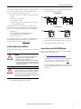
About the Adapters
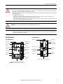
5069-AEN2TR Adapter
5069-AENTR Adapter
WARNING:
• If you connect or disconnect wiring while the field-side power is on, an electric arc can occur. This could cause an explosion in hazardous location installations.
Be sure that power is removed or the area is nonhazardous before proceeding.
• When used in a Class I, Division 2, hazardous location, this equipment must be mounted in a suitable enclosure with proper wiring method that complies with
the governing electrical codes.
• 5069-AEN2TR EtherNet/IP adapter only:
– When you insert or remove the SD memory Card while power is on, an electric arc can occur. This could cause an explosion in hazardous location
installations. Be sure that power is removed or the area is nonhazardous before proceeding.
– When you press the reset button while power is on, an electric arc can occur. This could cause an explosion in hazardous location installations. Be sure that
power is removed or the area is nonhazardous before proceeding.
WARNING: Do not use the USB port in hazardous locations. (5069-AEN2TR EtherNet/IP adapter only.)
IMPORTANT Any illustrations, charts, sample programs, and layout examples shown in this publication are intended solely for the purposes of example. Since there are
many variables and requirements associated with any particular installation, Rockwell Automation does not assume responsibility or liability for actual use
based upon the examples shown in this publication.
DIN Rail Latches
Status Indicators
SD Card Slot
Reset Button
Four-character
Display
Module Power and
Sensor/Actuator
Power Status
Indicators
MOD Power RTB
SA Power RTB
USB Port
Rotary Switches
Ethernet ports 1 and 2 (on bottom of the adapter)
IMPORTANT: Port 1 is the front port and port 2 is the rear port.
MOD Power Bus
Connector
SA Power Bus
Connector
DIN Rail Latch Status Indicators
Module Power and
Sensor/Actuator Power
Status Indicators
Rotary switches
(on side of adapter)
Power RTB
Ethernet port 2 (on bottom of the adapter)
MOD Power Bus
Connector
SA Power Bus
Connector
Ethernet port 1

6 Rockwell Automation Publication 5069-IN003C-EN-P - December 2016
5069 Compact I/O EtherNet/IP Adapters
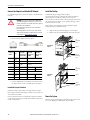
Install a 5069 Compact I/O System
Before you install the adapter, verify that you have the following:
System Planning
Follow these rules when planning your system configuration:
• 5069-AEN2TR adapter only — You must mount the DIN rail
horizontally.
Rockwell Automation does not support a 5069 Compact I/O
system that is installed vertically if it uses a 5069-AEN2TR
adapter.
• The adapter is the left-most component in the bank.
• Local 5069 Compact I/O modules are installed to the right of
the adapter.
• The adapter can communicate with as many as 31 local I/O
modules.
• Before powerup, verify that the end cap is installed on the
right-most 5069 Compact I/O module in the system.
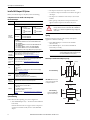
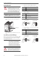
Spacing
Maintain spacing from enclosure walls, wireways, and adjacent
equipment. Consider the following:
• 5069-AEN2TR adapter - You must mount the DIN
rail horizontally.
• 5069-AENTR adapter - You can mount the DIN rail
horizontally or vertically.
5069 Compact I/O EtherNet/IP Adapter Spacing
Components Needed to Install a 5069 Compact I/O
EtherNet/IP Adapter
Component Description
Removable
Terminal
Blocks (RTB)
One of the following RTB types for each power type:
5069-AEN2TR
• MOD Power (system-
side power)
– 5069-RTB4-SCREW
RTB
– 5069-RTB4-SPRING
RTB
• SA Power (field-side
power)
– 5069-RTB6-SCREW
RTB
– 5069-RTB6-SPRING
RTB
5069-AENTR
Power (MOD Power and SA Power on same terminal)
• 5069-RTB5-SCREW RTB
• 5069-RTB5-SPRING RTB
IMPORTANT: You must order RTBs separately. The RTBs are available in
5069 RTB kits.
• The 5069-RTB64-SCREW kit contains the 5069-RTB6-SCREW and 5069-
RTB4-SCREW RTBs.
• The 5069-RTB64-SPRING kit contains the 5069-RTB6-SPRING and 5069-
RTB4-SPRING RTBs.
• The 5069-RTB5-SCREW kit contains the 5069-RTB5-SCREW RTBs.
• The 5069-RTB5-SPRING kit contains the 5069-RTB5-SPRING RTBs.
We recommend that you order only the RTB type that your system requires.
External
power supply
for Module
(MOD) Power
A power supply that is adequately sized to provide MOD power, that is,
system-side power, to the 5069 Compact I/O system.
For more information, see System Power Considerations on page 8.
External
power supply
for Sensor/
Actuator (SA)
Power
A power supply that is adequately sized to provide SA power, that is, field-
side power, to the 5069 Compact I/O system.
For more information, see System Power Considerations on page 8.
Tools
You use the following tools to wire the RTBs:
• Screwdriver
• Wire stripper
• Wires
For more information on available wire sizes and wire insulation stripping
length, see Specifications on page 18.
DIN rail
Compatible zinc-plated, chromate-passivated steel DIN rail.
You can use the following DIN rails:
• EN50022 - 35 x 7.5 mm (1.38 x 0.30 in.)
• EN50022-35 x 15 mm (1.38 x 0.59 in.) - 5069-AENTR only
EtherNet/IP
network
components
You must install the network and all required components.
Software
If you do not use the rotary switches to set the adapter IP address, you can use
the following software to set the IP address:
• DHCP server
• BootP DHCP EtherNet/IP Commissioning Tool
• RSLinx® Classic software
For more information, see Set the Network Internet Protocol (IP) Address on
page 8.
ATTENTION: Do not discard the end cap. Use this end cap to cover
the exposed interconnections on the last module on the DIN rail.
Failure to do so could result in equipment damage or injury from
electric shock.
IMPORTANT When you mount the DIN rail vertically, the
operating ambient temperature must be derated to
30% of the maximum Ta or 42 °C (108 °F).
Top
Bottom
SideSide
Adapter
5069 Compact I/O
End cap
5069 Compact I/O
IMPORTANT: Allow 25 mm (1 in.)
of space on all sides of the system
for adequate ventilation.
Adapter
5069 Compact I/O
5069 Compact I/O
Horizontal Mounting
Vertical Mounting
Only the 5069-AENTR adapter
supports vertical mounting.
Top
Bottom
SideSide
End cap

Rockwell Automation Publication 5069-IN003C-EN-P - December 2016 7
5069 Compact I/O EtherNet/IP Adapters
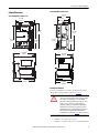
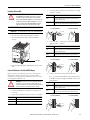
Adapter Dimensions
5069-AEN2TR Adapter Dimensions
5069-AENTR Adapter Dimensions
Ground Considerations
You must ground DIN rails according to the Industrial Automation
Wiring and Grounding Guidelines, publication
1770-4.1
You can use the following DIN rails with the adapters:
• EN50022 - 35 x 7.5 mm (1.38 x 0.30 in.)
• EN50022 - 35 x 15 mm (1.38 x 0.59 in.) - 5069-AENTR only
98.10 mm
(3.86 in.)
137.84 mm
(5.43 in.)
123.00 mm
(4.84 in.)
143.97 mm
(5.67 in.)
136.81 mm
(5.39 in.)
130.31 mm
(5.13 in.)
101.66 mm
(4.00 in.)
ATTENTION: This product is grounded through the DIN rail to
chassis ground. Use zinc-plated chromate-passivated steel DIN
rail to assure proper grounding. The use of other DIN rail
materials (for example, aluminum or plastic) that can corrode,
oxidize, or are poor conductors, can result in improper or
intermittent grounding. Secure DIN rail to mounting surface
approximately every 200 mm (7.8 in.) and use end-anchors
appropriately. Be sure to ground the DIN rail properly. Refer to
Industrial Automation Wiring and Grounding Guidelines,
Rockwell Automation publication
1770-4.1 for more information.
R
R
2
1
56.00 mm
(2.20 in.)
132.40 mm
(5.21 in.)
123.00 mm
(4.84 in.)
139.00 mm
(5.47 in.)
105.30 mm
(4.15 in.)
98.80 mm
(3.89 in.)
59.56 mm
(2.34 in.)

8 Rockwell Automation Publication 5069-IN003C-EN-P - December 2016
5069 Compact I/O EtherNet/IP Adapters
System Power Considerations
5069 Compact I/O EtherNet/IP adapters provide power to a 5069
Compact I/O system via RTBs that are connected to external power
supplies and installed on the adapter.
The RTBs provide the following power to the system.
• You must use SELV-listed power supplies for MOD power and
SA power if there are Functional Safety modules that are
connected to the 5069 Compact I/O system.
• If the adapter is used in a safety system, more restrictions can
apply to the power supply used for SA power. See the Technical
Data publications for the individual Safety I/O modules to
determine power supply restrictions.
• Not all Class 2/SELV-listed power supplies are certified for use
in all applications, for example, nonhazardous and hazardous
environments.
For more information, see the following:
• EtherNet/IP Communication Modules in Logix5000 Control
Systems User Manual, publication
ENET-UM004
• 5069 Compact I/O Modules Specifications Technical Data,
publication
5069-TD001.
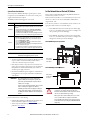
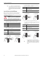
Set the Network Internet Protocol (IP) Address
5069 Compact I/O EtherNet/IP adapters ship DHCP-enabled and
with their rotary switches set to 000.
If the network uses 192.168.1.x, we recommend that you use the rotary
switches to set the last octet of network IP address. Valid numbers
range from 001…254.
To use the rotary switches to set the IP address, turn the switches to the
appropriate numbers before you install the adapter.
• 5069-AEN2TR - The bottom switch represents the first digit
in the octet, the middle switch represents the second digit, and
the top switch represents the third digit.
• 5069-AENTR - The left-most switch represents the first digit
in the octet, the middle switch represents the second digit, and
the right-most switch represents the third digit.
5069-AEN2TR Adapter Rotary Switches
5069-AENTR Adapter Rotary Switches
Power Type Description
MOD Power
System-side power that is used to operate the 5069 Compact I/O system. MOD
power is provided through the MOD power RTB and passed across the MOD
power bus.
• You must limit the MOD power source to 10 A, max, at 18...32V DC.
• Confirm that the external MOD power supply is adequately sized for the
total MOD power bus current draw in the system.
For example, if the total MOD power current draw, including current inrush
requirements, is 5 A, you can use a MOD power supply that is limited to 5 A.
SA Power
Field-side power that is used to power field-side devices. SA power is
provided through the SA power RTB and passed across the SA power bus.
• If you are using DC voltage for SA power, you must limit the SA power
source to 10 A, max at 18…32V DC.
• If you are using AC voltage for SA power, you must limit the SA power
source to 10 A, max at 18…240V AC.
• Confirm that the external SA power supply is sized adequately for the total
SA power current draw in the system.
For example, if the total SA power current draw, including current inrush
requirements, is 4 A, you can use an SA power supply that is limited to 4 A.
IMPORTANT The 5069 Compact I/O EtherNet/IP adapters do not have an
embedded power supply that powers the system.
IMPORTANT We recommend that you use separate external power
supplies for MOD power and SA power respectively. This
practice helps prevent unintended consequences that can
result if you use one supply.
If you use separate external power supplies, the loss of power
from one external power supply does not affect the
availability of power from the other supply. For example, if
separate external power supplies are used and SA power is
lost, MOD power remains available for the 5069 Compact I/O
modules.
WARNING: When you change switch settings while power is on,
an electric arc can occur. This could cause an explosion in
hazardous location installations. Be sure that power is removed
or the area is nonhazardous before proceeding.
When you press the reset button while power is on, an electric
arc can occur. This could cause an explosion in hazardous
location installations. Be sure that power is removed or the area
is nonhazardous before proceeding. (5069-AEN2TR EtherNet/IP
adapter only)
Rotary switches
are on the front
of the adapter.
Rotary switches
are on the side of
the adapter.

Rockwell Automation Publication 5069-IN003C-EN-P - December 2016 9
5069 Compact I/O EtherNet/IP Adapters
At powerup, the adapter reads the rotary switches to determine if they
are set to a valid number for the last octet of the IP address. If the
settings are a valid number, these conditions result:
• IP address = 192.168.1.xxx (where xxx represents the switch
settings)
• Subnet mask = 255.255.255.0
• Gateway address = 0.0.0.0
• The adapter does not have an assigned host name, nor does it
use any Domain Name System
If the network does not use 192.168.1.x, do not change the switch
positions before you install the adapter. After you install and power up
the adapter, you can use the following to set the network IP address:
• DHCP server
• BootP DHCP EtherNet/IP Commissioning Tool -
5069-AENTR only uses the DHCP mode
• RSLinx Classic software
For more information on how to use software to set the IP address, see
the EtherNet/IP Communication Modules in Logix5000 Control
Systems User Manual, publication
ENET-UM004.
Install the Adapter onto the DIN Rail
The adapter is the first and left-most module in a 5069 Compact I/O
system.
1. Confirm that the DIN rail latches are closed.
2. If the DIN rail latches are open, gently push the rear latch back
until the front latch pops up and clicks.
3. Position the adapter so that the back of it faces the DIN rail.
4. Press the adapter against the DIN rail until you hear a click.
5. Confirm that the adapter is latched securely.
Connect Power to the 5069-AEN2TR Adapter
Before you connect MOD power or SA power to a 5069-AEN2TR
adapter, complete the following tasks:
• Read
System Power Considerations on page 8.
• Confirm that the external power supplies that supply MOD
power and SA power are adequately sized for your 5069
Compact I/O system. For more information, see
page 8.
• Install the MOD power RTB and the SA power RTB, if used,
on the 5069-AEN2TR adapter before you connect power to
the adapter.
ATTENTION:
• Do not remove or replace the Adapter Module while power is
applied. Interruption of the backplane can result in
unintentional operation or machine motion.
• During DIN rail mounting of all devices, be sure that all debris
(metal chips, wire strands) is kept from falling into the adapter
or modules. Debris that falls into the adapter or modules could
cause damage on powerup.
WARNING: If you insert or remove the Adapter Module while
power is on, an electric arc can occur. This could cause an explosion
in hazardous location installations. The module does not support
"Removal and Insertion Under Power" (RIUP) capability. Do not
connect or disconnect the module while power is applied. Be sure
that power is removed before proceeding.
Open
Position
Closed
Position
5069-AEN2TR Adapter
Open
Position
Closed
Position
5069-AENTR Adapter

10 Rockwell Automation Publication 5069-IN003C-EN-P - December 2016
5069 Compact I/O EtherNet/IP Adapters
Install the MOD Power RTB
1. Hook the bottom of the MOD power RTB on the adapter.
2. Push the RTB against the adapter until the RTB clicks into
place.
.
3. Push the RTB handle against the RTB until you hear another
click.
Connect MOD Power to the 5069-AEN2TR Adapter
Before you connect an external power source to the MOD power RTB,
make sure that the MOD power source is properly sized. For example,
if the total MOD power current draw is 4 A, you can use a MOD
power supply that is limited to 4 A.
1. Verify that the external power supply is not powered.
2. Strip insulation from the wires that you connect to the RTB.
3. Connect the 24V DC(+) wire from the external power supply
to the first + terminal.
4. Connect the 24V DC(—) wire from the external power supply
to the first — terminal.
WARNING: If you connect or disconnect the Removable Terminal
Block (RTB) with power applied, an Electric Arc can occur. This
could cause an explosion in hazardous location installations.
The Removable Terminal Block (RTB) does not support "Removal
and Insertion Under Power" (RIUP) capability. Do not connect or
disconnect the Removable Terminal Block (RTB) while power is
applied. Be sure that power is removed before proceeding.
IMPORTANT The MOD Power RTB is used only on the 5069-AEN2TR
adapter.
IMPORTANT Your application can require a power control device, for
example, a switch, between the external 24V DC power
source and the adapter to control when the module is
powered. If so, you must install the power control device at
the VDC+ terminal on the removable terminal block.
If you install the power control device at the VDC- terminal,
the adapter can fail to power up or power down properly.
WARNING: If you connect or disconnect wiring while the field-
side power is on, an electric arc can occur. This could cause an
explosion in hazardous location installations. Be sure that power is
removed or the area is nonhazardous before proceeding.
ADAPTER
COMPACT 5000
AENTR
Compact I/O
Compact I/O
™
5069-AEN2TR
MOD Power RTB
RTB Type Action
Screw Strip12 mm (0.47 in.) of insulation from the wires.
Spring Strip 10 mm (0.39 in.) of insulation from the wires.
RTB Type Action
Screw
1. Insert the wire into the terminal.
2. Turn the screwdriver to close the terminal on the wire. Torque the
screw to 0.4 N•m (3.5 lb•in).
Spring
Push the wire into the terminal.
If the wire is too thin, crimp a wire ferrule on the wire and insert it.
RTB Type Action
Screw
1. Insert the wire into the terminal.
2. Turn the screwdriver to close the terminal on the wire. Torque the
screw to 0.4 N•m (3.5 lb•in).
Spring
Push the wire into the terminal.
If the wire is too thin, crimp a wire ferrule on the wire and insert it.
5069-RTB4-SPRING RTB
5069-RTB4-SCREW RTB
5069-RTB4-SPRING RTB
5069-RTB4-SCREW RTB

Rockwell Automation Publication 5069-IN003C-EN-P - December 2016 11
5069 Compact I/O EtherNet/IP Adapters
Install the SA Power RTB
1. Hook the bottom of the SA power RTB on the adapter.
2. Push the RTB against the adapter until the RTB clicks
into place.
3. Push the RTB handle against the RTB until you hear another
click.
Connect SA DC Power to the 5069-AEN2TR Adapter
Before you connect an external DC power source to the SA power
RTB, make sure that the SA power source is properly sized. For
example, if the total SA power current draw is 7 A, you can use an SA
power supply that is limited to 7 A.
1. Confirm that MOD power and all sources of SA power are
turned off.
2. Strip insulation from the wires that you connect to the RTB.
3. Connect the DC(+) wire from the external DC power supply
to the first + terminal.
4. Connect the DC(—) wire from the external SA DC power
supply to the first — terminal.
5. Connect a wire from an earth ground location to the
first terminal on the RTB. The earth ground location can
be the external SA power supply, the DIN rail, or other earth
ground location.
WARNING: If you connect or disconnect the Removable Terminal
Block (RTB) with power applied, an Electric Arc can occur. This
could cause an explosion in hazardous location installations.
The Removable Terminal Block (RTB) does not support "Removal
and Insertion Under Power" (RIUP) capability. Do not connect or
disconnect the Removable Terminal Block (RTB) while power is
applied. Be sure that power is removed before proceeding.
IMPORTANT The SA Power RTB is used only on the 5069-AEN2TR adapter.
WARNING: If you connect or disconnect wiring while the field-
side power is on, an electric arc can occur. This could cause an
explosion in hazardous location installations. Be sure that power is
removed or the area is nonhazardous before proceeding.
RTB Type Action
Screw Strip12 mm (0.47 in.) of insulation from the wires.
Spring Strip 10 mm (0.39 in.) of insulation from the wires.
ADAPTER
COMPACT 5000
AENTR
Compact I/O
Compact I/O
™
5069-AEN2TR
SA Power RTB
RTB Type Action
Screw
1. Insert the wire into the terminal.
2. Turn the screwdriver to close the terminal on the wire. Torque the
screw to 0.4 N•m (3.5 lb•in).
Spring
Push the wire into the terminal.
If the wire is too thin, crimp a wire ferrule on the wire and insert it.
RTB Type Action
Screw
1. Insert the wire into the terminal.
2. Turn the screwdriver to close the terminal on the wire. Torque the
screw to 0.4 N•m (3.5 lb•in).
Spring
Push the wire into the terminal.
If the wire is too thin, crimp a wire ferrule on the wire and insert it.
RTB Type Action
Screw
1. Insert the wire into the terminal.
2. Turn the screwdriver to close the terminal on the wire. Torque the
screw to 0.4 N•m (3.5 lb•in).
Spring
Push the wire into the terminal.
If the wire is too thin, crimp a wire ferrule on the wire and insert it.
5069-RTB6-SPRING RTB
5069-RTB6-SCREW RTB
5069-RTB6-SPRING RTB
5069-RTB6-SCREW RTB
5069-RTB6-SPRING RTB
5069-RTB6-SCREW RTB

12 Rockwell Automation Publication 5069-IN003C-EN-P - December 2016
5069 Compact I/O EtherNet/IP Adapters
Connect SA AC Power to the 5069-AEN2TR Adapter
Before you connect an external AC power source to the SA power
RTB, make sure that the SA power source is properly sized. For
example, if the total SA power current draw is 7 A, you can use an SA
power supply that is limited to 7 A.
1. Verify that the SA power source is not powered on.
2. Strip insulation from the wires that you connect to the RTB.
3. Connect the L1/AC(+) wire from the external SA AC power
source to the first + terminal.
4. Connect the L2/N/AC(—) wire from the external SA AC
power source to the first — terminal.
5. Connect a wire from an earth ground location to the
first terminal on the RTB. The earth ground location can
be the external SA power supply, the DIN rail, or other earth
ground location.
TIP
The symbol denotes an earth ground terminal that
provides a low impedance path between electrical circuits and
earth for functional purposes and provides noise immunity
improvement. This connection must be made for functional
purposes.
WARNING: If you connect or disconnect wiring while the field-
side power is on, an electric arc can occur. This could cause an
explosion in hazardous location installations. Be sure that power is
removed or the area is nonhazardous before proceeding.
RTB Type Action
Screw Strip12 mm (0.47 in.) of insulation from the wires.
Spring Strip 10 mm (0.39 in.) of insulation from the wires.
RTB Type Action
Screw
1. Insert the wire into the terminal.
2. Turn the screwdriver to close the terminal on the wire. Torque the
screw to 0.4 N•m (3.5 lb•in).
Spring
Push the wire into the terminal.
If the wire is too thin, crimp a wire ferrule on the wire and insert it.
5069-RTB6-SPRING RTB
5069-RTB6-SCREW RTB
RTB Type Action
Screw
1. Insert the wire into the terminal.
2. Turn the screwdriver to close the terminal on the wire. Torque the
screw to 0.4 N•m (3.5 lb•in).
Spring
Push the wire into the terminal.
If the wire is too thin, crimp a wire ferrule on the wire and insert it.
RTB Type Action
Screw
1. Insert the wire into the terminal.
2. Turn the screwdriver to close the terminal on the wire. Torque the
screw to 0.4 N•m (3.5 lb•in).
Spring
Push the wire into the terminal.
If the wire is too thin, crimp a wire ferrule on the wire and insert it.
TIP
The symbol denotes an earth ground terminal that
provides a low impedance path between electrical circuits and
earth for functional purposes and provides noise immunity
improvement. This connection must be made for functional
purposes.
5069-RTB6-SPRING RTB
5069-RTB6-SCREW RTB
5069-RTB6-SPRING RTB
5069-RTB6-SCREW RTB

Rockwell Automation Publication 5069-IN003C-EN-P - December 2016 13
5069 Compact I/O EtherNet/IP Adapters
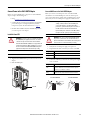
Connect Power to the 5069-AENTR Adapter
Before you connect MOD power or SA power to a 5069-AENTR
adapter, complete the following tasks:
• Read
System Power Considerations on page 8.
• Confirm that the external power supplies that supply MOD
power and SA power are adequately sized for your 5069
Compact I/O system. For more information, see
page 8.
• Install the Power RTB on the 5069-AENTR adapter before
you connect power to the adapter.
Install the Power RTB
1. Align the Power RTB with the open connection area on the
adapter.
2. Push the RTB in place.
Connect MOD Power to the 5069-AENTR Adapter
Before you connect an external power source to the Power RTB
terminals that are used for MOD power, make sure that the power
source is properly sized. For example, if the total MOD power current
draw is 4 A, you can use a MOD power supply that is limited to 4 A.
1. Verify that the external power supply is not powered.
2. Strip insulation from the wires that you connect to the RTB.
3. Connect the 24V DC(+) wire from the external power supply
to the + terminal.
WARNING: If you connect or disconnect the Removable Terminal
Block (RTB) with power applied, an Electric Arc can occur. This
could cause an explosion in hazardous location installations.
The Removable Terminal Block (RTB) does not support "Removal
and Insertion Under Power" (RIUP) capability. Do not connect or
disconnect the Removable Terminal Block (RTB) while power is
applied. Be sure that power is removed before proceeding.
IMPORTANT The Power RTB is used only on the 5069-AENTR adapter.
MOD POWER
SA POWER
ADAPTER
5069-AENTR
2
1
Compact I/O
™
OK
NET
LINK 1
LINK 2
WARNING
-EXPLOSION HAZARD
Do Not Disconnect
While Circuit is Live
Unless Area Is Known
To Be Non-Hazardous
A VERTISSEMENT
-RISQUE D’EXPLOSION.
Ne Pas Debrancher Tant Que
Le Circuit Est Sous Tension,
A Moins Qu’LL Ne S’agisse D’un
Emplacement Non Dengereux
Power RTB
IMPORTANT Your application can require a power control device, for
example, a switch, between the external 24V DC power
source and the adapter to control when the module is
powered. If so, you must install the power control device at
the VDC+ terminal on the removable terminal block.
If you install the power control device at the VDC- terminal,
the adapter can fail to power up or power down properly.
WARNING: If you connect or disconnect wiring while the field-
side power is on, an electric arc can occur. This could cause an
explosion in hazardous location installations. Be sure that power is
removed or the area is nonhazardous before proceeding.
RTB Type Action
Screw Strip 10 mm (0.39 in.) of insulation from the wires.
Spring Strip 10 mm (0.39 in.) of insulation from the wires.
RTB Type Action
Screw
1. Insert the wire into the terminal.
2. Turn the screwdriver to close the terminal on the wire. Torque the
screw to 0.5…0.6 N•m (4.4…5.3 lb•in).
Spring
Push the wire into the terminal.
If the wire is too thin, crimp a wire ferrule on the wire and insert it.
5069-RTB5-SPRING RTB
5069-RTB5-SCREW RTB

14 Rockwell Automation Publication 5069-IN003C-EN-P - December 2016
5069 Compact I/O EtherNet/IP Adapters
4. Connect the 24V DC(—) wire from the external power supply
to the — terminal.
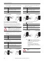
Connect SA DC Power to the 5069-AENTR Adapter
Before you connect an external power source to the Power RTB
terminals that are used for SA power, make sure that the power source
is properly sized. For example, if the total SA power current draw is
7 A, you can use an SA power supply that is limited to 7 A.
1. Confirm that MOD power and all sources of SA power are
turned off.
2. Strip insulation from the wires that you connect to the RTB.
3. Connect the DC(+) wire from the external DC power supply
to the +/L terminal.
4. Connect the DC(—) wire from the external SA DC power
supply to the —/N terminal.
5. Connect a wire from an earth ground location to
the terminal on the RTB.
RTB Type Action
Screw
1. Insert the wire into the terminal.
2. Turn the screwdriver to close the terminal on the wire. Torque the
screw to 0.5…0.6 N•m (4.4…5.3 lb•in).
Spring
Push the wire into the terminal.
If the wire is too thin, crimp a wire ferrule on the wire and insert it.
WARNING: If you connect or disconnect wiring while the field-
side power is on, an electric arc can occur. This could cause an
explosion in hazardous location installations. Be sure that power is
removed or the area is nonhazardous before proceeding.
RTB Type Action
Screw Strip 10 mm (0.39 in.) of insulation from the wires.
Spring Strip 10 mm (0.39 in.) of insulation from the wires.
RTB Type Action
Screw
1. Insert the wire into the terminal.
2. Turn the screwdriver to close the terminal on the wire. Torque the
screw to 0.5…0.6 N•m (4.4…5.3 lb•in).
Spring
Push the wire into the terminal.
If the wire is too thin, crimp a wire ferrule on the wire and insert it.
5069-RTB5-SPRING RTB
5069-RTB5-SCREW RTB
5069-RTB5-SPRING RTB
5069-RTB5-SCREW RTB
RTB Type Action
Screw
1. Insert the wire into the terminal.
2. Turn the screwdriver to close the terminal on the wire. Torque the
screw to 0.5…0.6 N•m (4.4…5.3 lb•in).
Spring
Push the wire into the terminal.
If the wire is too thin, crimp a wire ferrule on the wire and insert it.
RTB Type Action
Screw
1. Insert the wire into the terminal.
2. Turn the screwdriver to close the terminal on the wire. Torque the
screw to 0.5…0.6 N•m (4.4…5.3 lb•in).
Spring
Push the wire into the terminal.
If the wire is too thin, crimp a wire ferrule on the wire and insert it.
TIP
The symbol denotes an earth ground terminal that
provides a low impedance path between electrical circuits and
earth for protective earth purposes and provides noise
immunity improvement.
We recommend that you use the AWG 14 wire type or
equivalent for grounding purposes. Make sure that you
securely connect the ground to proper earth grounding via the
ground bus.
WARNING: Protection is relied upon an external branch circuit
protection.
5069-RTB5-SPRING RTB
5069-RTB5-SCREW RTB
5069-RTB5-SPRING RTB
5069-RTB5-SCREW RTB

Rockwell Automation Publication 5069-IN003C-EN-P - December 2016 15
5069 Compact I/O EtherNet/IP Adapters
Connect SA AC Power to the 5069-AENTR Adapter
Before you connect an external power source to the Power RTB
terminals that are used for SA power, make sure that the power source
is properly sized. For example, if the total SA power current draw is
7 A, you can use an SA power supply that is limited to 7 A.
1. Verify that the SA power source is not powered on.
2. Strip insulation from the wires that you connect to the RTB.
3. Connect the L1/AC(+) wire from the external SA AC power
source to the +/L terminal.
4. Connect the L2/N/AC(—) wire from the external SA AC
power source to the —/N terminal.
5. Connect a wire from an earth ground location to the
terminal on the RTB.
Disconnect Wires from RTBs
If necessary, complete the following tasks to disconnect wires from any
RTB on the adapter. The actions apply to every catalog number for an
RTB type.
For example, the graphic shows the 5069-RTB4-SCREW RTB.
However, you complete the same actions to disconnect wires for any
Screw-type RTB.
WARNING: If you connect or disconnect wiring while the field-
side power is on, an electric arc can occur. This could cause an
explosion in hazardous location installations. Be sure that power is
removed or the area is nonhazardous before proceeding.
RTB Type Action
Screw Strip 10 mm (0.39 in.) of insulation from the wires.
Spring Strip 10 mm (0.39 in.) of insulation from the wires.
RTB Type Action
Screw
1. Insert the wire into the terminal.
2. Turn the screwdriver to close the terminal on the wire. Torque the
screw to 0.5…0.6 N•m (4.4…5.3 lb•in).
Spring
Push the wire into the terminal.
If the wire is too thin, crimp a wire ferrule on the wire and insert it.
RTB Type Action
Screw
1. Insert the wire into the terminal.
2. Turn the screwdriver to close the terminal on the wire. Torque the
screw to 0.5…0.6 N•m (4.4…5.3 lb•in).
Spring
Push the wire into the terminal.
If the wire is too thin, crimp a wire ferrule on the wire and insert it.
5069-RTB5-SPRING RTB
5069-RTB5-SCREW RTB
5069-RTB5-SPRING RTB
5069-RTB5-SCREW RTB
RTB Type Action
Screw
1. Insert the wire into the terminal.
2. Turn the screwdriver to close the terminal on the wire. Torque the
screw to 0.5…0.6 N•m (4.4…5.3 lb•in).
Spring
Push the wire into the terminal.
If the wire is too thin, crimp a wire ferrule on the wire and insert it.
TIP
The symbol denotes an earth ground terminal that
provides a low impedance path between electrical circuits and
earth for protective earth purposes and provides noise
immunity improvement.
We recommend that you use the AWG14 wire type or
equivalent for grounding purposes. Make sure that you
securely connect the ground to proper earth grounding via the
ground bus.
WARNING: If you connect or disconnect wiring while the field-
side power is on, an electric arc can occur. This could cause an
explosion in hazardous location installations. Be sure that power
is removed or the area is nonhazardous before proceeding.
RTB Type Action
Screw
1. Turn the screwdriver counter-clockwise to open the terminal.
2. Remove the wire.
Spring
1. Insert and hold a screwdriver in the right-side terminal.
2. Remove the wire.
3. Pull out the screwdriver.
5069-RTB5-SPRING RTB
5069-RTB5-SCREW RTB
Spring-type RTB
Screw-type RTB

16 Rockwell Automation Publication 5069-IN003C-EN-P - December 2016
5069 Compact I/O EtherNet/IP Adapters
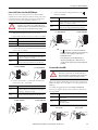
Connect the Adapter to an EtherNet/IP Network
Use an RJ45 straight cable to connect the adapter to an EtherNet/IP
network.
1. If needed, wire the RJ45 connector as shown.
2. Connect the RJ45 cable to an Ethernet port on the bottom of
the adapter. You can connect two RJ45 cables to the adapter.
Install 5069 Compact I/O Modules
Install 5069 Compact I/O modules on the right side of the adapter.
If the end cap is installed on the adapter, you must remove it before you
can install the I/O modules.
For more information on how to install 5069 Compact I/O modules,
see the installation instructions available with each 5069 Compact I/O
module catalog number.
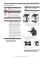
Install the End Cap
A 5069-ECR end cap is shipped with the adapter.
You must install an end cap on the right side of the last module in a
5069 Compact I/O system. The end cap covers the exposed
interconnections on the last module in the system. If you do not install
the end cap before powering the system, equipment damage or injury
from electric shock can result.
If the end cap is not installed and you have installed all required
modules in the system, install the end cap.
1. Align the end cap with interlocking pieces on the adapter.
2. Push the end cap toward the DIN rail until it locks into place.
Power the System
After the end cap is installed on the last module in the system, turn on
power to the MOD power RTB and the SA power RTB.
WARNING: If you connect or disconnect the communication
cable with power applied to this module or any device on the
network, an electric arc can occur. This could cause an explosion
in hazardous location installations.
Be sure that power is removed or the area is nonhazardous
before proceeding.
This warning applies to connections to ports 1 and 2 on both
adapters. For more information on where the ports are located
on the adapter, see
About the Adapters on page 5.
Connector
Number
Color
1585J 8-pin
Cables with
Support for 10/
100/1000 Mbps
1585J 8-pin
Cables with
Support for 10/
100 Mbps
1585J 4-pin
Cables with
Support for 10/
100 Mbps
1
White/
Orange
BI_DA+ TxData +
2 Orange BI_DA- TxData -
3
White/
Green
BI_DB+ Recv Data +
4 Blue BI_DC+ Unused N/A
5 White/Blue BI_DC- Unused N/A
6 Green BI_DB- Recv Data -
7
White/
Brown
BI_DD+ Unused N/A
8 Brown BI_DD- Unused N/A
ADAPTER
COMPACT 5000
AENTR
5069-AEN2TR
Compact I/O
C
ompact I/O
™
Top
Interlocking
Pieces
End Cap
Bottom
Interlocking
Pieces
Top
Interlocking
Pieces
End Cap
Bottom
Interlocking
Pieces
5069-AEN2TR
Adapter
5069-AENTR
Adapter

Rockwell Automation Publication 5069-IN003C-EN-P - December 2016 17
5069 Compact I/O EtherNet/IP Adapters
Remove or Replace the Adapter
1. Turn off power to the MOD power RTB and, if used, the SA
power RTB.
2. Disconnect wires from the RTBs. For more information, see
Disconnect Wires from RTBs on page 15.
3. Remove the RTBs:
– 5069-AEN2TR adapter - Pull the RTB handles to remove
the MOD power RTB and SA power RTB.
– 5069-AENTR adapter - Hold the top and bottom of the
RTB and pull the RTB off the adapter.
4. Remove the EtherNet/IP cable from the adapter.
5. Push down on the front of the DIN rail latches. A click
indicates that the DIN rail latches are open.
If the DIN rail latches fail to remain in the open position, hold
them down.
6. Pull the adapter off the DIN rail.
7. Repeat the installation steps that are described beginning at
Set
the Network Internet Protocol (IP) Address on page 8.
8. Apply MOD power and, if necessary, SA power to the system.
ATTENTION: Do not remove or replace an adapter while power is
applied. Interruption of the backplane can result in unintentional
operation or machine motion.
WARNING: If you insert or remove the Adapter Module while
power is on, an electric arc can occur. This could cause an
explosion in hazardous location installations. The module does
not support "Removal and Insertion Under Power" (RIUP)
capability. Do not connect or disconnect the module while power
is applied. Be sure that power is removed before proceeding.
IMPORTANT When you remove MOD power from a 5069 Compact I/O
EtherNet/IP adapter, you shut down power to all modules in
the 5069 Compact I/O system. That is, all system-side is
removed. When you remove SA power from the 5069
Compact I/O EtherNet/IP adapter, all field-side power that is
provided by the adapter is removed. If the system uses the SA
power provided by the SA power RTB on a 5069-FPD field
potential distributor, the system does not lose field-side
power to the right of the field potential distributor.
In this case, you must use a separate power source for the SA
power RTB on the field potential distributor.
We strongly recommend that you take the appropriate actions
to help prevent unintended consequences that can result
from a system power shutdown before removing MOD power
or SA power from the adapter or field potential distributor.
Despite the removal of field-side power from SA RTBs on the
adapter or field potential distributor, the 5069-OB16 and
5069-OB16F modules continue to receive field-side power
from an external power source connected to the LA (+) and
LA (–) terminals on the modules.
ATTENTION: Do not remove or replace a Terminal Base
unit while power is applied. Interruption of the
backplane can result in unintentional operation or
machine motion.
ADAPTER
COMPACT 5000
AENTR
ADAPTER
COMPACT 5000
AENTR
Compact I/O
Compact
I/O
™
5069-AEN2TR
SA Power RTBMOD Power RTB
Power RTB
Open
Position
5069-AEN2TR Adapter
Open
Position
5069-AENTR Adapter

18 Rockwell Automation Publication 5069-IN003C-EN-P - December 2016
5069 Compact I/O EtherNet/IP Adapters
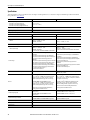
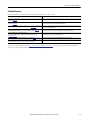
Specifications
This table includes a subset of specifications for the adapter. For full specifications, see the 5069 Compact I/O Modules Specifications Technical
Data, publication
5069-TD001.
Attribute 5069-AEN2TR 5069-AENTR
Temperature, operating
• IEC 60068-2-1 (Test Ad, Operating Cold)
• IEC 60068-2-2 (Test Bd, Operating Dry Heat)
• IEC 60068-2-14 (Test Nb, Operating Thermal Shock)
0 °C < Ta < +60 °C
(+32 °F < Ta < +140 °F)
Temperature, surrounding air, max 60 °C (140 °F)
Enclosure type rating None (open-style)
Voltage and current ratings
MOD Power 450 mA @ 18…32V DC 220 mA @ 18…32V DC
MOD Power Inrush 850 mA for 125 ms 1750 mA for 70 ms
SA Power
10 mA @ 0…32V DC
25 mA @ 0…240V AC, 47…63 Hz
ATEX/IECEx, 125V AC Max
5 mA @ 0…32V DC
2 mA @ 0…240V AC, 47…63 Hz
MOD Power (Passthrough) 9.55 A @ 18…32V DC 9.78 A @ 18…32V DC
SA Power (Passthrough)
9.95 A @ 0…32V DC
9.975 A @ 0…240V AC, 47…63 Hz
ATEX/IECEx, 125V AC Max
Do not exceed 10 A current draw at the MOD or SA Power RTB.
9.95 A @ 0…32V DC
9.975 A @ 0…240V AC, 47…63 Hz
Do not exceed 10 A current draw at the MOD or SA Power RTB.
Isolation voltage
300V (continuous), Basic Insulation Type, SA, and MOD Power
to Backplane
300V (continuous), Basic Insulation Type, SA to MOD Power
300V (continuous), Basic Insulation Type, Ethernet to Backplane
300V (continuous), Double Insulation Type, Ethernet to
MOD Power
300V (continuous), Double Insulation Type, Ethernet to SA Power
50V (continuous), Functional Insulation Type, Ethernet to USB
300V (continuous), Basic Insulation Type, USB to Backplane
300V (continuous), Double Insulation Type, USB to MOD Power
300V (continuous), Double Insulation Type, USB to SA Power
No isolation between Ethernet ports
Type tested at 1500V AC for 60 s
300V (continuous), Basic Insulation Type, SA, and MOD Power
to Backplane
300V (continuous), Basic Insulation Type, SA to MOD Power
300V (continuous), Basic Insulation Type, Ethernet to Backplane
Type tested at 1500V AC for 60 s
300V (continuous), Double Insulation Type, Ethernet to
MOD Power
300V (continuous), Double Insulation Type, Ethernet to SA Power
Type tested at 4242V DC for 60 s
No isolation between Ethernet ports
Recommended external overcurrent protection N/A
MOD Power: 10…12A @ 22.5…43.2 A2t, Fast Acting
SA Power: 20 A @ 250V AC
Wire size
5069-RTB4-SCREW, 5069-RTB6-SCREW connections:
0.5…1.5 mm
2
(22…16 AWG) solid or stranded copper wire
rated at 105 °C (221 °F), or greater, 3.5 mm (0.14 in.) max
diameter including insulation, single wire connection only.
5069-RTB4-SPRING, 5069-RTB6-SPRING connections:
0.5…1.5 mm
2
(22…16 AWG) solid or stranded copper wire
rated at 105 °C (221 °F), or greater, 2.9 mm (0.11 in.) max
diameter including insulation, single wire connection only.
Ethernet connections: Ethernet Cabling and Installation
according to IEC 61918 and IEC 61784-5-2.
0.25…2.5 mm
2
(22…14 AWG) solid or stranded copper wire
rated at 105 °C (221 °F), or greater, 1.2 mm (3/64 in.) insulation
m, single wire connection only.
Grounding: 2.5 mm
2
(14 AWG) solid or stranded copper wire
rated at 105 °C (221 °F), or greater, 3.5mm (0.14in) max
diameter including insulation, single wire connection only.
Ethernet connections: Ethernet Cabling and Installation
according to IEC 61918 and IEC 61784-5-2.
Insulation stripping length
5069-RTB4-SCREW, 5069-RTB6-SCREW connections:
12 mm (0.47 in.)
5069-RTB4-SPRING, 5069-RTB6-SPRING connections:
10 mm (0.39 in.)
5069-RTB5-SCREW connections: 10 mm (0.39 in.)
5069-RTB5-SPRING connections: 10 mm (0.39 in.)
Terminal block torque specifications
5069-RTB4-SCREW and 5069-RTB6-SCREW: 0.4 N•m (3.5 lb•in)
5069-RTB4-SPRING and 5069-RTB6-SPRING: Not applicable
5069-RTB5-SCREW: 0.5…0.6 N•m (4.4…5.3 lb•in)
5069-RTB5-SPRING: Not applicable
North American Temp Code T4
ATEX Temp Code T4
IECEx Temp Code T4

Rockwell Automation Publication 5069-IN003C-EN-P - December 2016 19
5069 Compact I/O EtherNet/IP Adapters
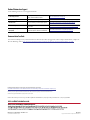
Additional Resources
For more information on the products that are described in this publication, use these resources.
You can view or download publications at
http://www.rockwellautomation.com/literature/. To order paper copies of technical documentation,
contact your local Allen-Bradley distributor or Rockwell Automation sales representative.
Resource Description
5069 Compact I/O Modules Specifications Technical Data,
publication
5069-TD001
Provides 5069 Compact I/O EtherNet/IP adapter and 5069 Compact I/O module specifications.
EtherNet/IP Communication Modules in Logix5000 Control Systems User Manual,
publication ENET-UM004
Describes how to use the 5069 Compact I/O EtherNet/IP adapters.
Ethernet Design Considerations Reference Manual, publication ENET-RM002
Describes how to use EtherNet/IP adapters with Logix5000controllers and communicate with other
devices on the EtherNet/IP network.
EtherNet/IP Embedded Switch Technology Application Guide, publication ENET-AP005
Describes how to install, configure, and maintain linear and Device Level Ring (DLR) networks by using
Allen-Bradley® EtherNet/IP devices that are equipped with embedded switch technology.
EtherNet/IP Media Planning and Installation Manual
This manual is available from the Open DeviceNet Vendor Association (ODVA) at
http://www.odva.org
Describes how to use the required media components and provides information on how to plan for, install,
verify, troubleshoot, and certify your EtherNet/IP network.
Industrial Automation Wiring and Grounding Guidelines, publication 1770-4.1 Provides general guidelines for installing a Rockwell Automation industrial system.
Product Certifications website,
http://www.rockwellautomation.com/global/certification/overview.page
Provides declarations of conformity, certificates, and other certification details.

Rockwell Otomasyon Ticaret A.Ş., Kar Plaza İş Merkezi E Blok Kat:6 34752 İçerenköy, İstanbul, Tel: +90 (216) 5698400
Allen-Bradley, Compact I/O, Logix5000, Rockwell Automation, Rockwell Software, RSLinx, and Studio 5000 Logix Designer are trademarks of Rockwell Automation, Inc.
Trademarks not belonging to Rockwell Automation are property of their respective companies.
Rockwell Automation maintains current product environmental information on its website at
http://www.rockwellautomation.com/rockwellautomation/about-us/sustainability-ethics/product-environmental-compliance.page.
Publication 5069-IN003C-EN-P - December 2016 PN-389292
Supersedes Publication 5069-IN003B-EN-P - July 2016 Copyright © 2016 Rockwell Automation, Inc. All rights reserved. Printed in the U.S.A.
Rockwell Automation Support
Use the following resources to access support information.
Documentation Feedback
Your comments will help us serve your documentation needs better. If you have any suggestions on how to improve this document, complete the
How Are We Doing? form at
http://literature.rockwellautomation.com/idc/groups/literature/documents/du/ra-du002_-en-e.pdf.
Technical Support Center
Knowledgebase Articles, How-to Videos, FAQs, Chat, User
Forums, and Product Notification Updates.
https://rockwellautomation.custhelp.com/
Local Technical Support Phone Numbers Locate the phone number for your country.
http://www.rockwellautomation.com/global/support/get-support-now.page
Direct Dial Codes
Find the Direct Dial Code for your product. Use the code to
route your call directly to a technical support engineer.
http://www.rockwellautomation.com/global/support/direct-dial.page
Literature Library
Installation Instructions, Manuals, Brochures, and
Technical Data.
http://www.rockwellautomation.com/global/literature-library/overview.page
Product Compatibility and Download
Center (PCDC)
Get help determining how products interact, check
features and capabilities, and find associated firmware.
http://www.rockwellautomation.com/global/support/pcdc.page
-
 1
1
-
 2
2
-
 3
3
-
 4
4
-
 5
5
-
 6
6
-
 7
7
-
 8
8
-
 9
9
-
 10
10
-
 11
11
-
 12
12
-
 13
13
-
 14
14
-
 15
15
-
 16
16
-
 17
17
-
 18
18
-
 19
19
-
 20
20


Allen-Bradley Compact I/O 5069 series Installation Instructions Manual
- Typ
- Installation Instructions Manual
w innych językach
Powiązane artykuły


Inne dokumenty
-
Ideal Steel Crimp Connector, Model 412 18-4 AWG Instrukcja obsługi
-
-
-
 Platinum Tools 100054C Instrukcja obsługi
-
-
Buchanan 30-1452J Instrukcja obsługi
-
-
Ideal 30-340P Instrukcja instalacji
-
-
