
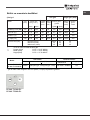
PC 640 X /HA PL
PC 631 X /HA PL
PC 640T(AN) R /HA PL
PC 640 T X /HA PL
PC 640T(OW) R /HA PL
PC 640T(AV) R /HA PL
English
Operating Instructions
HOB
Contents
Operating Instructions,1
Warnings,3
Assistance,7
Description of the appliance,8
Installation,12
Start-up and use,16
Precautions and tips,16
Maintenance and care,17
Troubleshooting,18
Spis treści
Instrukcja obsługi,1
Ostrzezenia,3
Serwis Techniczny,7
Opis urządzenia,8
Instalacja,19
Uruchomienie i użytkowanie,23
Zalecenia i środki ostrożności,23
Konserwacja i utrzymanie,24
Anomalie i środki zaradcze,25
Polski
Instrukcja obsługi
PŁYTA
Magyar
Használati útmutató
FŐZŐLAP
Tartalomjegyzék
Használati útmutató,1
Figyelmeztetések,4
Szerviz,7
A készülék leírása,9
Üzembe helyezés,26
Bekapcsolás és használat,30
Óvintézkedések és tanácsok,30
Karbantartás és ápolás,31
Hibaelhárítás,32
Eesti keeles
Kasutusjuhend
KEEDUPLAAT
Lietuvių k.
Naudojimo instrukcijos
HOB
Sisukord
Kasutusjuhend,1
Hoiatused,4
Klienditugi,7
Seadme kirjeldus,9
Paigaldamine,33
Käitamine ja kasutamine,37
Ettevaatusabinõud ja soovitused,37
Hooldus,38
Veaotsing,39
Turinys
Naudojimo instrukcijos,1
Įspėjimai,5
Pagalba,7
Prietaiso aprašymas,10
Montavimas,40
Įjungimas ir naudojimas,44
Atsargumo priemonės ir patarimai,44
Techninė priežiūra,45
Gedimų šalinimas,45

Latviešu valoda
Lietošanas instrukcija
PLĪTS VIRSMA
Türkçe
Kullanım talimatları
SETÜSTÜ
Română
Instrucţiuni de utilizare
HOB
Cuprins
Lietošanas instrukcija,2
Brīdinājumi,5
Palīdzība,7
Ierīces apraksts,10
Ierīkošana,47
Ieslēgšana un lietošana,51
Piesardzības pasākumi un ieteikumi,51
Tehniskā apkope un kopšana,52
Traucējumu novēršana,52
İçindekiler
Kullanım talimatları,2
Uyarı,5
Teknik Servis,7
Cihazın tanıtımı,11
Montaj,54
Başlatma ve kullanım,58
Önlemler ve tavsiyeler,58
Servis ve bakım,59
Arızalar ve çözümler,60
Sommario
Instrucţiuni de utilizare,2
Avertizări,6
Asistenţă ,7
Descrierea aparatului,11
Instalarea,61
Pornirea şi folosirea,65
Precauţii şi sfaturi,65
Întreţinere,66
Anomalii şi remedii,67

3
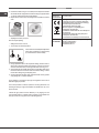
Warnings
WARNING: The appliance and its accessible parts
become hot during use. Care should be taken to
avoid touching heating elements. Children less than 8
years of age shall be kept away unless continuously
supervised. This appliance can be used by children
aged from 8 years and above and persons with
reduced physical, sensory or mental capabilities or
lack of experience and knowledge if they have been
given supervision or instruction concerning use of the
appliance in a safe way and understand the hazards
involved. Children shall not play with the appliance.
Cleaning and user maintenance shall not be made
by children without supervision.
WARNING: Unattended cooking on a hob with fat or
oil can be dangerous and may result in re. NEVER
try to extinguish a re with water, but switch off the
appliance and then cover ame e.g. with a lid or a
re blanket.
WARNING: Danger of re: do not store items on the
cooking surfaces.
Never use steam cleaners or pressure cleaners on
the appliance.
Remove any liquid from the lid before opening it. Do
not close the glass cover (if present) when the gas
burners or electric hotplates are still hot.
The appliance is not intended to be operated by
means of an external timer or separate remote
control system.
CAUTION: the use of inappropriate hob guards can
cause accidents.
Ostrzezenia
UWAGA: To urządzenie oraz jego dostępne części
silnie się rozgrzewają podczas użytkowania. Należy
uważać, aby nie dotknąć elementów grzejnych.
Nie pozwalać, aby dzieci poniżej 8 roku życia
zbliżały się do urządzenia, jeśli nie są pod stałym
nadzorem dorosłych. Z niniejszego urządzenia
mogą korzystać dzieci powyżej 8 roku życia i
osoby o ograniczonych zdolnościach zycznych,
zmysłowych bądź umysłowych, jak również osoby
nieposiadające doświadczenia lub znajomości
urządzenia, jeśli znajdują się one pod nadzorem
innych osób lub jeśli zostały pouczone na temat
bezpiecznego sposobu użycia urządzenia oraz
zdają sobie sprawę ze związanych z nim zagrożeń.
Dzieci nie powinny bawić się urządzeniem. Prace
związane z czyszczeniem i konserwacją nie mogą
być wykonywane przez dzieci, jeśli nie są one
nadzorowane.
UWAGA: Pozostawienie bez nadzoru na kuchence
tłuszczów i olejów może być niebezpieczne i może
spowodować pożar.
Nie należy NIGDY próbować ugasić płomieni/pożaru
wodą; należy wyłączyć urządzenie i przykryć płomień
np. pokrywką lub ognioodpornym kocem.
UWAGA: Ryzyko pożaru: nie pozostawiać
przedmiotów na powierzchniach grzejnych.
Nie stosować nigdy oczyszczaczy parowych lub
ciśnieniowych do czyszczenia urządzenia.
Usunąć ewentualne płyny na pokrywie przed jej
otwarciem. Nie zamykać szklanej pokrywy (jeśli jest
częścią wyposażenia), jeśli palniki gazowe lub płyta
elektryczna są jeszcze rozgrzane.
Urządzenie nie jest przeznaczone do włączania przy
użyciu zewnętrznego przekaźnika czasowego lub
zdalnego systemu sterowania.

4
UWAGA: użycie niewłaściwych zabezpieczeń płyty
może być przyczyną wypadków.
Figyelmeztetések
FIGYELEM: A készülék és annak hozzáférhető
részei a használat közben rendkívüli módon
felmelegedhetnek. Vigyázzon, hogy nehogy
hozzáérjen a fűtőelemekhez. Ha a gyermekek
nincsenek folyamatos felügyelet alatt, tartsa távol
a 8 éven aluli gyermekeket. Ezt a készüléket a 8
éves kort betöltött gyermekek, valamint a testileg,
érzékszervileg vagy szellemileg korlátozott, nem
hozzáértő, illetve a terméket nem ismerő személyek
csak megfelelő felügyelet mellett, vagy a készülék
biztonságos használatával kapcsolatos alapvető
utasítások és a kapcsolódó veszélyek ismeretében
használhatják. Vigyázzon, hogy a gyermekek ne
játsszanak a készülékkel. A tisztítási és karbantartási
műveleteket gyermekek felügyelet nélkül nem
végezhetik.
FIGYELEM: A tűzhelyen felügyelet nélkül otthagyott
zsír vagy olaj veszélyes lehet, és tüzet okozhat.
SOHA ne próbálja meg vízzel eloltani a tüzet, hanem
zárja el a készüléket, és takarja le a lángot például
fedővel vagy tűzálló takaróval.
FIGYELEM: Tűzveszély! Ne tároljon semmit a főző
felületeken!
A készülék tisztításához soha ne használ-jon
gőztisztítót vagy nagynyomású tisz-títót.
A fedő kinyitása előtt távolítsa el az összes folyadékot!
Ne csukja be az üveg fedőt (típustól függően) ha a
gáz égők vagy elektromos főzőmezők még melegek.
A készüléket nem szabad külső időmérővel vagy
különálló távirányító rendszerrel használni.
FIGYELEM: A főzőlap nem megfelelő használata
balesetet okozhat.
Hoiatused
HOIATUS: sisselülitatud seade ja selle
juurdepääsetavad osad muutuvad kasutamise
ajal kuumaks. Olge ettevaatlik ja vältige kontakti
kütteelementidega. Alla 8-aastased lapsed tuleb
hoida seadmest eemal, v.a. juhul, kui neile on
tagatud pidev järelevalve. Vanemad kui 8-aastased
lapsed ja isikud, kellel on vähenenud füüsilised
või vaimsed võimed või vähesed kogemused ja
oskused, võivad seda seadet kasutada juhul, kui on
tagatud nende järelevalve ning neile on antud juhised
seadme ohutuks kasutamiseks ja nad mõistavad
seadme kasutamisest tulenevaid ohte. Lapsed ei
tohi seadmega mängida. Lapsed võivad seadet
puhastada ja hooldada ainult järelevalve all.
HOIATUS: rasvas või õlis küpseva toidu jätmine
keeduplaadile järelevalveta on ohtlik ja võib
põhjustada tulekahju. Tulekahju kustutamiseks
ÄRGE kasutage vett, vaid lülitage seade välja ja
seejärel katke leek näiteks kaane või tuletekiga.
HOIATUS: Tuleoht: ärge hoidke keeduplaatidel
mingeid esemeid.
Ärge kasutage seadme puhastamiseks auru- ega
survepuhastusseadmeid.
Enne kaane avamist eemaldage sellele kogunenud
vedelik. Ärge sulgege klaaskaant (kui on olemas),
kui gaasipõletid või elektrilised keeduplaadid on veel
kuumad.
Seade ei ole mõeldud kasutamiseks koos välise
taimeri ega eraldiseisva kaugjuhtimissüsteemiga.
TÄHELEPANU: valede keeduplaadipiirete
kasutamine võib põhjustada õnnetusi.

5
Įspėjimai
ĮSPĖJIMAS! Prietaisas ir jo pasiekiamos dalys
naudojant įkaista. Būkite atsargūs, neprisilieskite
prie įkaitusių prietaiso dalių. Jaunesni nei 8 metų
vaikai gali būti prileidžiami prie prietaiso tik jei
juos prižiūri suaugusieji. Vyresni nei 8 metų vaikai
ir asmenys, turintys zinių, jutimo ar psichinių
sutrikimų arba nepakankamai žinių ar patirties, šiuo
prietaisu gali naudotis tik tuomet, jei jie prižiūrimi
arba instruktuojami, kaip saugiai naudoti prietaisą,
ir supranta kylančias grėsmes. Vaikams turi būti
draudžiama žaisti su prietaisu. Neprižiūrimi vaikai taip
pat negali valyti prietaiso ar atlikti jo priežiūros darbų.
ĮSPĖJIMAS! Ant įjungtos viryklės palikti indai su
riebalais ar aliejumi gali sukelti gaisrą. NIEKADA
nebandykite liepsnos gesinti vandeniu – išjunkite
prietaisą ir kuo nors uždenkite liepsną, pavyzdžiui,
dangčiu arba priešgaisriniu apklotu.
ĮSPĖJIMAS! Gaisro pavojus – ant viryklės nelaikykite
jokių daiktų.
Niekuomet nevalykite prietaiso gariniais ar slėginiais
valikliais.
Prieš atidarydami gaubtą nuo jo nuvalykite skysčius.
Neuždenkite stiklinio dangčio (jei sumontuotas), kol
neatvėso dujiniai degikliai arba elektrinė kaitlentė.
Prietaisas nevaldomas išoriniu laikmačiu arba atskira
nuotoline valdymo sistema.
ATSARGIAI! Netinkamų viryklės apsaugų naudojimas
gali sukelti nelaimingą atsitikimą.
Brīdinājumi
BRĪDINĀJUMS! Ierīce un tās atklātās daļas
lietošanas laikā stipri sakarst. Nepieskarieties
sakarsušajām ierīces daļām. Bērni, kuri ir jaunāki par
astoņiem gadiem, drīkst atrasties ierīces tuvumā tikai
stingrā pieaugušo uzraudzībā. Ierīci drīkst lietot bērni,
kuri ir sasnieguši astoņu gadu vecumu, bet personas
ar ierobežotām ziskajām, maņu vai garīgajām
spējām un personas, kurām nav ierīces lietošanas
pieredzes vai nepieciešamo zināšanu, - tikai tad, ja
tās tiek uzraudzītas vai ir atbilstoši informētas par
ierīces drošu lietošanu un iespējamajiem riskiem.
Bērni nedrīkst rotaļāties ar ierīci. Bērni nedrīkst bez
uzraudzības tīrīt ierīci un veikt tās apkopi.
BRĪDINĀJUMS! Atstājot uz ieslēgtas plīts virsmas
pannu ar taukiem vai eļļu, varat radīt ugunsgrēka
risku. NEKĀDĀ GADĪJUMĀ nemēģiniet dzēst uguni
ar ūdeni, bet izslēdziet plīti un nosedziet liesmu ar
vāku vai nedegošu pārsegu.
BRĪDINĀJUMS! Aizdegšanās risks: neglabājiet
priekšmetus uz plīts virsmas.
Ierīci nedrīkst tīrīt ar tvaika vai augstspiediena
tīrītājiem.
Pirms pārsega atvēršanas notīriet no tā visu
šķidrumu. Ja gāzes degļi vai elektriskās sildvirsmas
joprojām ir karstas, stikla pārsegu (ja tāds ir) nedrīkst
aizvērt.
Iekārtu nav paredzēts lietot kopā ar ārējo taimeri vai
atsevišķu tālvadības ierīci.
UZMANĪBU! Neatbilstošu plīts virsmas aizsargu
lietošana var izraisīt nelaimes gadījumus.
Uyarı
DİKKAT: Bu cihaz ve erişilebilen bölümleri, kullanım
sırasında çok sıcak olur. Dikkat etmek ve ısıtılan
parçalara dokunmaktan kaçınmak gerekir. Eğer
sürekli olarak gözetim altında değiller ise, 8 yaşından
küçük çocukları uzak tutunuz. Bu cihaz, eğer uygun
şekilde gözetim altında bulunuyorlar ise veya güvenli
şekilde cihazın kullanımı hakkında eğitim almışlar
ise ve ilişkin tehlikeler göz önünde bulundurulur ise,
8 yaşından itibaren çocuklar ve ziksel, duyusal
veya mental kapasitelerden yoksun veya tecrübe ve
bilgi sahibi olmayan kişiler tarafından kullanılabilir.

6
Çocuklar, cihaz ile oynamamalıdır. Temizlik ve bakım
işlemleri, denetimsiz olarak çocuklar tarafından
gerçekleştirilmemelidir.
DİKKAT: Gres yağları ve yağlar ile korumasız küçük
bir fırın bırakmak, tehlikeli olabilir ve bir yangına
neden olabilir.
Bir alevi/yangını su ile söndürmeye çalışmak ASLA
gerekmez, ancak cihazı kapatmak ve örneğin bir
kapak veya ateşe dayanıklı bir kapak ile alevin üzerini
örtmek gerekir.
DİKKAT: Yangın riski: pişirme yüzeyleri üzerinde
nesneler bırakmayınız.
Cihazı temizlerken asla buharlı yada yüksek basınçlı
temizleyiciler kullanmayınız.
Açmadan önce, kapağın üzerinde mevcut olan
muhtemel sıvıları temizleyiniz. Cam kapağı (mevcut
olduğu durumlarda) gaz brülörleri ya da elektrikli
levha hala sıcakken kapatmayınız.
Cihaz, harici bir süre ölçer veya ayrı uzaktan bir
kumanda sistemi aracılığıyla çalıştırılmak üzere
tasarlanmamıştır.
DİKKAT: uygun olmayan ocak koruyucularının
kullanılması, kazalara neden olabilir.
Avertizări
ATENŢIE: Acest aparat şi părţile sale accesibile devin
foarte calde în timpul folosirii. Trebuie să ţi atenţi şi
să nu atingeţi elementele de încălzire. Îndepărtaţi
copiii sub 8 ani dacă nu sunt supravegheaţi continuu.
Acest aparat poate utilizat de copiii de peste 8 ani
şi de persoane cu capacităţi zice, senzoriale sau
mentale reduse sau fără experienţă şi cunoştinţe
dacă se aă sub o supraveghere corespunzătoare
sau dacă au fost instruiţi cu privire la folosirea
aparatului în mod sigur şi dacă îşi dau seama de
pericolele corelate. Copiii nu trebuie să se joace cu
aparatul. Operaţiunile de curăţare şi de întreţinere nu
trebuie să e efectuate de copii fără supraveghere.
ATENŢIE: Lăsarea unui aragaz nesupravegheat cu
grăsimi şi uleiuri poate periculoasă şi poate provoca
un incendiu.
Nu trebuie NICIODATĂ să încercaţi să stingeţi o
acără/incendiu cu apă, ci trebuie să stingeţi aparatul
şi să acoperiţi acăra, de exemplu cu un capac sau
cu o pătură ignifugă.
ATENŢIE: Risc de incendiu: nu lăsaţi obiecte pe
suprafeţele de gătit.
Nu folosiţi niciodată aparate cu aburi sau sub
presiune pentru a curăţa aparatul.
Eliminaţi eventualele reziduuri de lichid de pe capac,
înainte de a-l deschide. Nu închideţi capacul din sticlă
(dacă este prezent) cu arzătoarele de gaz sau plita
electrică încă calde.
Aparatul nu trebuie pus în funcţiune prin intermediul
unui temporizator extern sau al unui sistem separat
de comandă la distanţă.
ATENŢIE: folosirea unor protecţii necorespunzătoare
ale plitei poate provoca accidente.

7
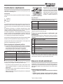
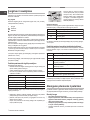
Assistance
Communicating:
• type of trouble
• appliance model (Mod.)
• serial number (S/N)
This information is found on the data plate located on the appliance and/or
on the packaging.
Serwis Techniczny
Podać:
• rodzaj usterki;
• model urządzenia (Mod.)
• numer seryjny (S/N)
Te ostatnie informacje można znaleźć na tabliczce znamionowej umieszczonej
na urządzeniu.
Szerviz
Adja meg az alábbiakat:
• az anomália típusa;
• a készülék modellje (Mod.)
• a készülék szériaszáma (S/N)
Az utóbbi információk a készüléken elhelyezett adattáblán találhatók.
Klienditugi
Hoidke käepärast järgmised andmed:
• tüüpi anomaalia
• seadme mudel (Mod.)
• seerianumber (S/N)
Need andmed leiate seadme andmeplaadilt ja/või pakendilt.
Pagalba
Informacija:
• tipas anomalija
• prietaiso modelis (Mod.)
• Serijos numeris (S/N)
Šią informaciją rasite duomenų plokštelėje, kuri yra ant prietaiso ir (arba)
pakuotės.
Palīdzība
Paziņojums:
• tipa anomālija
• ierīces modelis (Mod.)
• sērijas numurs (S/N)
Šī informācija ir norādīta uz tehnisko datu plāksnītes, kas piestiprināta ierīcei
un/vai tās iepakojumam.
Teknik Servis
şağıdaki bilgileri bildiriniz:
• arıza tipi
• cihazın modeli (Mod.)
• seri numarası (S/N)
Bu bilgiler cihaz ve / veya ambalajı üzerinde bulunan özellik etiketinde bulunur.
Satış Sonrası Hizmetler:
Indesit Company Beyaz Eşya Sanayi ve Ticaret A.Ş.
Balmumcu Cad. Karahasan Sok.
No: 11, 34349 – Balmumcu Beşiktaş – İstanbul
Tel: (0212) 355 53 00
Cihazın ömrü 10 yıldır
Asistenţă
Comunicaţi:
• tipul de anomalie;
• modelul maşinii (Mod.);
• numărul de serie (S/N).
Aceste informaţii se găsesc pe plăcuţa de caracteristici din frigider, în partea
de jos, în stânga.

8
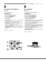
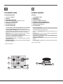
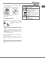
Description of the appliance
Overall view
1. Support Grid for COOKWARE
2. GAS BURNERS
3. ELECTRIC HOTPLATE*
4. Indicator light for ELECTRIC HOTPLATE*
5. Control Knobs for ELECTRIC HOTPLATE*
6. Control Knobs for GAS BURNERS
7. Ignition for GAS BURNERS
8. SAFETY DEVICES
• ELECTRIC HOTPLATES* may have different diameters and operate at
different power levels.
• The INDICATOR LIGHT FOR ELECTRIC HOTPLATE* switches on
whenever the selector knob is moved from the ‘off’ position.
• GAS BURNERS differ in size and power. Use the diameter of the cookware
to choose the most appropriate burner to cook with.
• Control Knobs for GAS BURNERS and ELECTRIC HOTPLATE* adjust
the power or the size of the ame.
• GAS BURNER IGNITION enables a specic burner to be lit automatically.
• SAFETY DEVICE stops the gas flow if the flame is accidentally
extinguished.
* Only available on certain models.
Opis urządzenia
Widok ogólny
1. Ruszty do ustawiania NACZYŃ DO GOTOWANIA
2. PALNIKI GAZOWE
3. PŁYTA ELEKTRYCZNA*
4. Kontrolka działania PŁYTY ELEKTRYCZNEJ*
5. Pokrętła sterujące PALNIKÓW GAZOWYCH
6. Pokrętła sterujące PŁYTY ELEKTRYCZNEJ*
7. Świeca zapłonowa PALNIKÓW GAZOWYCH*
8. URZĄDZENIE ZABEZPIECZAJĄCE*
• PŁYTY ELEKTRYCZNE* mogą mieć różne średnice i charakteryzować
się różną mocą: „normalne” lub “szybkie”; szybkie płyty można rozpoznać
dzięki czerwonemu znakowi umieszczonemu na środku.
• Kontrolka działania PŁYTY ELEKTRYCZNEJ* zapala się dla każdej
pozycji pokrętła z wyjątkiem pozycji wyłączenia
• PALNIKI GAZOWE posiadają różne wymiary i moce. Należy wybrać ten
palnik, który jest najbardziej odpowiedni dla średnicy używanego naczynia.
• Pokrętła sterowania PALNIKAMI GAZOWYMI oraz PŁYTĄ
ELEKTRYCZNĄ* do regulowania płomienia lub mocy.
• Świeca zapłonowa PALNIKÓW GAZOWYCH* umożliwia automatyczne
zapalenie wybranego palnika.
• URZĄDZENIE ZABEZPIECZAJĄCE* w razie przypadkowego zgaśnięcia
płomienia przerywa dopływ gazu.
* Tylko w niektórych modelach.
1
4
5
2
6
8
7
3

9
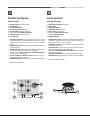
A készülék leírása
A készülék áttekintése
1. Főzőedénytartó RÁCSOK
2. GÁZÉGŐK
3. ELEKTROMOS FŐZŐLAPOK*
4. ELEKTROMOS FŐZŐLAPOK működését jelző lámpa*
5. Gázégő vezérlő TEKERŐGOMBOK
6. FŐZŐLAPOK szabályzógombja*
7. GYÚJTÓGYERTYA gázégők*
8. BIZTONSÁGI SZERKEZET*
• Az ELEKTROMOS FŐZŐLAPOK MŰKÖDÉSÉT JELZŐ LÁMPA*
bekapcsol, ha a választó gombot elforgatja a kikapcsolt pozícióról.
• Az ELEKTROMOS FŐZŐMEZŐK különböző méretűek és különböző
teljesítményűek lehetnek. A teljesítmény szint lehet „normál” vagy „gyors”
(az utóbbi a főzőmező közepénél levő piros foltról ismerhető fel.).
• GÁZÉGŐK: Különböző méretűek és teljesítményűek. Válassza a
használni kívánt edény átmérőjének leginkább megfelelőt.
• A GÁZ ÉGŐ és ELEKTROMOS FŐZŐMEZŐ üzemeltető gombok*
szabályozzák a teljesítményt és a láng nagyságát.
• GYÚJTÓGYERTYA gázégők*: A kiválasztott gázégő automatikus
meggyújtására szolgál.
• BIZTONSÁGI SZERKEZET*: A láng véletlen kialvása esetén a gázellátás
kikapcsolására szolgál.
* Csak néhány modellnél
Seadme kirjeldus
Ülevaade
1. Rest KEEDUNÕU JAOKS
2. GAASIPÕLETID
3. ELEKTRILINE PLAAT*
4. Operation lamp ELEKTRILIIT PLAAT*
5. GAASIPÕLETITE REGULEERIMISE NUPUD
6. ELEKTRILIIT PLAAT REGULEERIMISE NUPUD*
7. GAASIPÕLETITE SÜÜTENUPP*
8. OHUTUSSEADISED*
• ELECTRIC GAASIPLIIDID* võib olla erineva läbimõõduga ja tegutsevad
eri võimsusega. Need võimsusega võib olla “normaalne” või “kiire” (viimane
võib eristada teistest punane laik keset pliit).
• Operation lamp ELEKTRILIIT PLAAT* uled iga nupp asendisse erinema
maha.
• GAASIPÕLETID on erineva suuruse ja võimsusega. Kasutage põleti jaoks
kõige sobivama läbimõõduga keedunõud.
• GAASIPÕLETITE ja ELEKTRILIIT PLAAT* REGULEERIMISE NUPUD
leegi või võimu reguleerimiseks.
• GAASIPÕLETI SÜÜTENUPP* võimaldab vastava põleti automaatselt
süüdata.
• OHUTUSSEADIS* seiskab gaasivoolu, kui leek peaks juhuslikult kustuma.
*Ainult mõnedel mudelitel.
1
4
5
2
6
8
7
3

10
Prietaiso aprašymas
Bendras vaizdas
1. GAMINIMO INDO laikančiosios grotelės
2. DUJŲ DEGIKLIAI
3. ELEKTROS KAITVIETĖ*
4. ELEKTROS KAITVIETĖ indikatorius*
5. DUJINIŲ DEGIKLIŲ valdymo rankenėlės
6. Valdymo rankenėlių ELEKTROS KAITVIETĖ*
7. DUJINIŲ DEGIKLIŲ uždegimo funkcija*
8. SAUGOS ĮTAISAI*
• ELEKTROS KAITVIETĖS* gali turėti skirtingus skersmenis ir veikti
skirtingais galios lygiais. Šios galios lygiai gali būti “normalus” arba “greitas”
(pastarasis gali būti atskirti nuo kitų, raudonos vietoje nuo kaitvietės
viduryje).
• ELEKTROS KAITVIETĖ indikatorius* įsijungia, kai selektoriaus rankenėlę
persikėlė iš “Išjungta”.
• DUJINIAI DEGIKLIAI skiriasi dydžiu ir galia. Naudokite tokio skersmens
gaminimo indus, kurie geriausiai tinka tam tikram degikliui.
• Valdymo rankenėlių DUJINIŲ DEGIKLIŲ ir ELEKTROS KAITVIETĖ*
reguliuoja galią, arba liepsnos dydį.
• DUJINIO DEGIKLIO UŽDEGIMO FUNKCIJA* suteikia galimybę
automatiškai uždegti tam tikrą degiklį.
• APSAUGINIS ĮTAISAS* sustabdo dujų srautą, jei liepsna netyčia užgęsta.
* Yra tik tam tikruose modeliuose.
Ierīces apraksts
Vispārīga informācija
1. GATAVOŠANAS TRAUKU balsta režģis
2. GĀZES DEGĻI
3. ELEKTRISKĀ PLĪTIŅA*
4. ELEKTRISKĀ PLĪTIŅA indikators*
5. GĀZES DEGĻU vadības slēdži
6. Vadības pogas ELEKTRISKĀ PLĪTIŅA*
7. Aizdedzes GĀZES DEGĻIEM*
8. DROŠĪBAS IERĪCES*
• ELEKTRISKĀS PLATES* var būt dažāda diametra un darbojas dažādos
varas līmeņos. Šie barošanas līmenis var būt “normāls” vai “ātrā” (tā var
atšķirt no citiem ar sarkanu vietas vidū plītiņas).
• ELEKTRISKĀ PLĪTIŅA indikators* ieslēdzas, kad selektora svira tiek
pārvietota no “off” pozīcijā.
• GĀZES DEGĻIEM ir dažādi izmēri un jauda. Gatavojot izvēlieties
gatavošanas trauka diametram atbilstošāko degli.
• Vadības pogas GĀZES DEGĻIEM un ELEKTRISKO PLATES * pielāgotu
jaudu vai no liesmas lieluma.
• GĀZES DEGĻA AIZDEDZE* ļauj automātiski aizdedzināt īpašu degli.
• DROŠĪBAS IERĪCE* aptur gāzes plūsmu, ja liesma tiek nejauši nodzēsta.
* Pieejams tikai noteiktiem modeļiem.
1
4
5
2
6
8
7
3

11
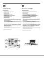
Cihazın tanıtımı
Genel görünüm
1. PİŞİRME KAPLARI için destek ızgaraları
2. GAZ BRÜLÖRLERİ
3. ELEKTRİKLİ LEVHA*
4. ELEKTRİKLİ LEVHA çalışma ışığı*
5. GAZ BRÜLÖRLERİ için kumanda düğmeleri*
6. ELEKTRİKLİ LEVHA için kumanda düğmeleri*
7. GAZ BRÜLÖRLERİ yakma bujisi*
8. EMNİYET DÜZENEĞİ*
• ELEKTRİK PLAKALARI, değişik çapta ve farklı güçlerde olabilirler:
“normal” veya “hızlı”,hızlı olanları ortasındaki kırmızı damga nedeniyle
diğerleri tarafından tanınırlar.
• Elektrikli LEVHA ÇALISMA LAMBASI* düğmenin kapalı konumu hariç
her konumunda yanar
• GAZ BRÜLÖRLERI farklı ebat ve güçlere sahiptir. Kullanacağınız kabın
çapına en uygun olanı seçiniz.
• Alev ve gücün ayarlanması için GAZ BRÜLÖRLERI ve ELEKTRIKLI
LEVHA kumanda düğmeleri *.
• GAZ BRÜLÖRLERI ÇAKMAKLARI* seçilmiş olan brülörün otomatik
olarak yakılmasını sağlar.
• EMNIYET DONANIMI* alev kazara söndüğünde, gaz çıkışını durdurur.
* Sadece bazı modellerde mevcut.
Descrierea aparatului
Vedere de ansamblu
1. Grătare de sprijin pentru RECIPIENTELE DE COACERE
2. ARZĂTOARE PE GAZ
3. PLITĂ ELECTRICĂ*
4. Indicator de FUNCŢIONARE AL PLITEI ELECTRICE*
5. SELECTOARE DE COMANDĂ ale ARZĂTOARELOR PE GAZ
6. SELECTOARE DE COMANDĂ ale PLITEI ELECTRICE *
7. Dispozitiv de aprindere al ARZĂTOARELOR PE GAZ *
8. DISPOZITIV DE SIGURANŢĂ*
• PLITE ELECTRICE pot avea diametre şi puteri diferite: „normale“ sau
„rapide“, acestea din urmă se deosebesc de celelalte prin prezenţa unui
bulin roşu în centru.
• Indicatorul DE FUNCŢIONARE AL PLITEIELECTRICE* se aprinde în
orice poziţie aselectorului, cu excepţia celei de oprit.
• ARZĂTOARELE PE GAZ sunt de diferite dimensiunişi puteri. Alegeţi-le
pe cele adecvate diametruluirecipientului utilizat.
• Selectoarele de comandă ale ARZĂTOARELOR PEGAZ şi ale PLITEI
ELECTRICE* sunt folosite pentrureglarea ăcării şi a puterii acesteia.
• Dispozitivul de aprindere al ARZĂTOARELOR PEGAZ* permite
aprinderea automată a arzătoaruluiprestabilit.
• DISPOZITIVUL DE SIGURANŢĂ* este utilizat încazul stingerii accidentale
a ăcării, împiedicândscurgerile de gaz.
* Valabile doar pentru anumite modele.
1
4
5
2
6
8
7
3

12
GB
Installation
! Before operating your new appliance please read this instruction booklet
carefully. It contains important information for safe use, installation and care
of the appliance.
! Please keep these operating instructions for future reference. Pass them on
to possible new owners of the appliance.
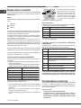
Positioning
! Keep packaging material out of the reach of children. It can become a choking
or suffocation hazard (see Precautions and tips).
! The appliance must be installed by a qualied professional according to the
instructions provided. Incorrect installation may cause harm to people and
animals or may damage property.
! This unit may be installed and used only in permanently ventilated rooms
in accordance with current national regulations. The following requirements
must be observed:
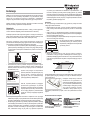
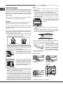
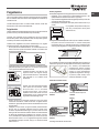
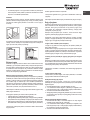
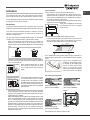
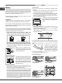
• The room must be equipped with an air extraction system that expels
any combustion fumes. This may consist of a hood or an electric fan that
automatically starts each time the appliance is switched on.
In a chimney stack or branched flue.
(exclusively for cooking appliances)
Directly to
the Outside
• The room must also allow proper air circulation, as air is needed for
combustion to occur normally. The ow of air must not be less than 2 m
3
/h
per kW of installed power.
The air circulation system may take air directly
from the outside by means of a pipe with an
inner cross section of at least 100 cm
2
; the
opening must not be vulnerable to any type
of blockages.
The system can also provide the air needed for
combustion indirectly, i.e. from adjacent rooms
tted with air circulation tubes as described
above. However, these rooms must not be
communal rooms, bedrooms or rooms that
may present a re hazard.
• Intensive and prolonged use of the appliance may necessitate
supplemental ventilation, e.g. opening a window or increasing the power
of the air intake system (if present).
• Liquid petroleum gas sinks to the oor as it is heavier than air. Therefore,
rooms containing LPG cylinders must also be equipped with vents to allow
gas to escape in the event of a leak. As a result LPG cylinders, whether
partially or completely full, must not be installed or stored in rooms or
storage areas that are below ground level (cellars, etc.). It is advisable to
keep only the cylinder being used in the room, positioned so that it is not
subject to heat produced by external sources (ovens, replaces, stoves,
etc. ) which could raise the temperature of the cylinder above 50°C.
A
Examples of
ventilation holes
for comburant air.
Enlarging the ventilation slot
between window and floor.
Adjacent
Room
Room to be
Vented
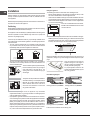
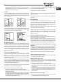
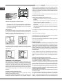
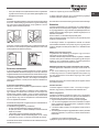
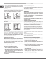
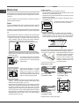
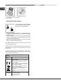
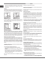
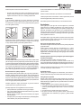
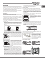
Fitting the appliance
The following precautions must be taken when installing the hob:
• Kitchen cabinets adjacent to the appliance and taller than the top of the
hob must be at least 200 mm from the edge of the hob.
• Hoods must be installed according to their relative installation instruction
manuals and at a minimum distance of 650 mm from the hob (see gure).
• Place the wall cabinets adjacent to the hood at a minimum height of 420
mm from the hob (see gure).
If the hob is installed beneath a wall cabinet,
the latter must be situated at a minimum of 700
mm above the hob.
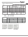
• The installation cavity should have the dimensions indicated in the gure.
Fastening hooks are provided, allowing you to fasten the hob to tops that
are between 20 and 40 mm thick. To ensure the hob is securely fastened
to the top, we recommend you use all the hooks provided.
555 mm
55 mm
475 mm
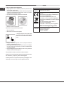
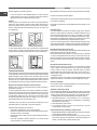
Before the installation remove the grids and burners from the hob and turn it
upside down, making sure you don’t damage the thermocouples and spark
plugs.
Apply the seals that come with the
appliance along the outer edges of
the hob to prevent any passage of air,
humidity and water (see Figure).
For proper application make sure the
surfaces to be sealed are clean, dry and
free of any grease/oil.
Hook fastening diagram
Hooking position for top H=20mm Hooking position for top H=30mm
Front
Hooking position for top H=40mm Back
! Use the hooks contained in the “accessory pack”.
600mm min.
420mm min.
650mm min.

GB
13
• Where the hob is not installed over a built-in oven, a wooden panel must
be installed as insulation. This must be placed at a minimum distance of
20 mm from the lower part of the hob.
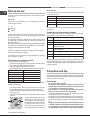
Ventilation
To ensure adequate ventilation, the back panel of the cabinet must be
removed. It is advisable to install the oven so that it rests on two strips of
wood, or on a completely at surface with an opening of at least 45 x 560
mm (see diagrams).
560 mm.
45 mm.
Where a hob is installed above an oven without a forced ventilation cooling
system, adequate ventilation must be provided inside the cabinet by means
of air holes through which air can pass (see gure).
Electrical connection
Hobs equipped with a three-pole power supply cable are designed to operate
with alternating current at the voltage and frequency indicated on the data
plate (this is located on the lower part of the appliance). The earth wire in the
cable has a green and yellow cover. If the appliance is to be installed above
a built-in electric oven, the electrical connection of the hob and the oven must
be carried out separately, both for electrical safety purposes and to make
extracting the oven easier.
Connecting the supply cable to the mains
Install a standardised plug corresponding to the load indicated on the data
plate.
The appliance must be directly connected to the mains using an omnipolar
circuit-breaker with a minimum contact opening of 3 mm installed between
the appliance and the mains.
The circuit-breaker must be suitable for the charge indicated and must comply
with current electrical regulations (the earthing wire must not be interrupted
by the circuit-breaker). The supply cable must not come into contact with
surfaces with temperatures higher than 50°C.
! The installer must ensure that the correct electrical connection has been
made and that it is compliant with safety regulations.
Before connecting to the power supply, make sure that:
• the appliance is earthed and the plug is compliant with the law.
• the socket can withstand the maximum power of the appliance, which is
indicated on the data plate.
• the voltage is in the range between the values indicated on the data plate.
• the socket is compatible with the plug of the appliance. If the socket is
incompatible with the plug, ask an authorised technician to replace it. Do
not use extension cords or multiple sockets.
! Once the appliance has been installed, the power supply cable and the
electrical socket must be easily accessible.
! The cable must not be bent or compressed.
! The cable must be checked regularly and replaced by authorised technicians
only (see Assistance).
! The manufacturer declines any liability should these safety measures not
be observed.
Gas connection
The appliance should be connected to the main gas supply or to a gas
cylinder in compliance with current national regulations. Before carrying out
the connection, make sure the cooker is compatible with the gas supply you
wish to use. If this is not the case, follow the instructions indicated in the
paragraph “Adapting to different types of gas.”
When using liquid gas from a cylinder, install a pressure regulator which
complies with current national regulations.
! Check that the pressure of the gas supply is consistent with the values
indicated in Table 1 (“Burner and nozzle specications”). This will ensure the
safe operation and longevity of your appliance while maintaining efcient
energy consumption.
Connection with a rigid pipe (copper or steel)
! Connection to the gas system must be carried out in such a way as not to
place any strain of any kind on the appliance.
There is an adjustable L-shaped pipe tting on the appliance supply ramp
and this is tted with a seal in order to prevent leaks. The seal must always
be replaced after rotating the pipe tting (seal provided with appliance). The
gas supply pipe tting is a threaded 1/2 gas cylindrical male attachment.
Connecting a flexible jointless stainless steel pipe to a threaded
attachment
The gas supply pipe tting is a threaded 1/2 gas cylindrical male attachment.
These pipes must be installed so that they are never longer than 2000 mm
when fully extended. Once connection has been carried out, make sure that
the exible metal pipe does not touch any moving parts and is not compressed.
! Only use pipes and seals that comply with current national regulations.
Checking the tightness of the connection
! When the installation process is complete, check the pipe ttings for leaks
using a soapy solution. Never use a ame.
Adapting to different types of gas
To adapt the hob to a different type of gas other than default type (indicated
on the rating plate at the base of the hob or on the packaging), the burner
nozzles should be replaced as follows:
1. Remove the hob grids and slide the burners off their seats.
2. Unscrew the nozzles using a 7 mm socket spanner, and replace them
with nozzles for the new type of gas (see table 1 “Burner and nozzle
characteristics”).
3. Reassemble the parts following the above procedure in the reverse order.
4. Once this procedure is nished, replace the old rating sticker with one
indicating the new type of gas used. Sticker are available from any of our
Service Centres.
Replacing the Triple ring burner nozzles
1. Remove the pan supports and lift the burners out of their housing. The
burner consists of two separate parts (see pictures).

14
GB
2. Unscrew the nozzles using a 7 mm socket spanner. Replace the nozzles
with models that are congured for use with the new type of gas (see Table
1). The two nozzles have the same hole diameter.
3. Replace all the components by completing the above operations in reverse
order.
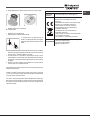
• Adjusting the burners’ primary air
Does not require adjusting.
• Setting the burners to minimum
1. Turn the tap to the low ame position.
2. Remove the knob and adjust the adjustment
screw, which is positioned in or next to the tap
pin, until the ame is small but steady.
3. Having adjusted the ame to the required low setting, while the burner is
alight, quickly change the position of the knob from minimum to maximum
and vice versa several times, checking that the ame does not go out.
4. Some appliances have a safety device (thermocouple) tted. If the device
fails to work when the burners are set to the low ame setting, increase
this low ame setting using the adjusting screw.
5. Once the adjustment has been made, replace the seals on the by-passes
using sealing wax or a similar substance.
! If the appliance is connected to liquid gas, the regulation screw must be
fastened as tightly as possible.
! Once this procedure is nished, replace the old rating sticker with one
indicating the new type of gas used. Stickers are available from any of our
Service Centres.
! Should the gas pressure used be different (or vary slightly) from the
recommended pressure, a suitable pressure regulator must be tted to the
inlet pipe (in order to comply with current national regulations).
Electrical
connections
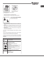
DATA PLATE
EU Regulation no. 66/2014 implementing
Directive 2009/125/EC.
standard EN 60350-2
standard EN 30-2-1
ECODESIGN
see data plate
This appliance conforms to the following
European Economic Community directives:
- 2006/95/EC dated 12/12/06 (Low Voltage)
and subsequent amendments
- 2004/108/EC dated 15/12/04
(Electromagnetic Compatibility) and
subsequent amendments
- 93/68/EEC dated 22/07/93 and subsequent
amendments.
- 2009/142/EC dated 30/11/06 (Gas) and
subsequent amendments
- 2012/19/EU and subsequent amendments.

GB
15
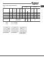
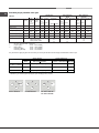
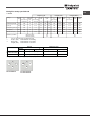
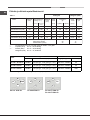
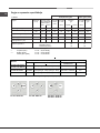
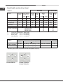
Table 1 Liquid Gas Natural Gas
Burner Diameter Thermal Thermal By-pass Nozzle Flow* Thermal Nozzle Flow*
power power 1/100 1/100 (g/h) power 1/100 (l/h)
kW kW kW
(p.c.s.*) (p.c.s.*) (p.c.s.*)
(mm) Reduced Nominal (mm) (mm) *** ** Nominal (mm)
Supply pressures Nominal (mbar)
Minimum (mbar)
Maximum (mbar)
28-30
20
35
37
25
45
20
17
25
Reduced Fast (RR)
Fast (R)
Semi Fast (S)
Auxiliary (A)
Triple Crown (TC)
100
100
75
55
130
0.80
0.80
0.45
0.45
1.65
2.70
3.10
1.75
1.05
3.50
39
39
28
28
61
80
86
64
50
65x2
196
225
127
76
254
193
221
125
75
250
2.70
3.10
1.75
1.05
3.50
122(H3)
132(H3)
96(Z)
79(6)
103x2
257
295
167
100
333
Burner and nozzle specifications
* At 15°C and 1013,25 mbar - dry gas
** Propane P.C.S. = 50.37 MJ/Kg
*** Butane P.C.S. = 49.47 MJ/Kg
Natural P.C.S. = 37.78 MJ/m³
PC 631 X/HA PL
R
Ø145
S
PC 640 X/HA PL
R
S
S
AA
PC 640 T X/HA PL
PC 640 T R/HA PL
RR
TC
S
A

16
GB
Start-up and use
! The position of the corresponding gas burner or electric hotplate* is shown
on every knob.
Gas burners
Each burner can be adjusted to one of the following settings using the
corresponding control knob:
● Off
Maximum
Minimum
To light one of the burners, hold a lit match or lighter near the burner and, at
the same time, press down and turn the corresponding knob anti-clockwise
to the maximum setting.
Since the burner is tted with a safety device, the knob should be pressed
for approximately 2-3 seconds to allow the automatic device keeping the
ame alight to heat up.
When using models with an gas burner ignition, to light the selected burner press
down and turn the corresponding knob anticlockwise to maximum position,
keeping it pressed until the burner has ignitied.
! If a ame is accidentally extinguished, turn off the control knob and wait for
at least 1 minute before trying to relight it.
To switch off the burner, turn the knob in a clockwise direction until it stops
(when reaches the “●” position).
Practical advice on using the burners
To ensure the burners operate efciently:
• Use appropriate cookware for each burner (see table) so that the ames
do not extend beyond the bottom of the cookware.
• Always use cookware with a at base and a cover.
• When the contents of the pan reach boiling point, turn the knob to minimum.
Rapid (R)
Reduced Rapid (RR)
Semi Rapid (S)
Auxiliary (A)
Triple Crown (TC)
Ø Cookware Diameter (cm)
24 - 26
24 - 26
16 - 20
10 - 14
24 - 26
Burner
Pans to be used on 60 cm hobs
To identify the type of burner, refer to the designs in the section entitled, “Burner
and Nozzle Specications”.
• For maximum stability, always make sure that the pan supports are
correctly tted and that each pan is placed centrally over the burner.
• Pan handles should be positioned in line with one of the support bars on
the pan support grid.
• Pan handle should be positioned so not to protrude beyond the front edge
of the hob.
The more variable aspect in terms of pan
stability can often be the pan itself, (or
the positioning of that pan during use).
Well balanced pans, with at bases that
are placed centrally over the burner,
with the pan handles aligned with one
of the support ngers obviously offer the
greatest stability.
Electric hotplates*
The corresponding knob may be turned clockwise or anti-clockwise and set
to six different positions:
Normal or Fast PlateSetting
Off
Minimum power
Intermediate powers
Maximum power
0
1
2-5
6
When the selector knob is in any position other than the off position, the ‘on’
light comes on.
Practical advice on using the electric hotplates*
To avoid heat loss and damage to the hotplates, use pans with a at base,
whose diameter is no less than that of the hotplate itself.
Setting
0
1
2
3
4
5
6
Normal or Fast Plate
Off
Cooking vegetables, fish
Cooking patatoes (using steam) soups,
chickpeas, beans.
Continuing the cooking of large quantities of
food, minestrone.
For roasting (average)
For roasting (above average)
For browning and reaching a boil in a short time
! Before using the hotplates for the rst time, you should heat them at maximum
temperature for approximately 4 minutes, without placing any pans on them.
During this initial stage, their protective coating hardens and reaches its
maximum resistance.
Precautions and tips
! This appliance has been designed and manufactured in compliance with
international safety standards. The following warnings are provided for safety
reasons and must be read carefully.
General safety
• This is a class 3 built-in appliance.
• Gas appliances require regular air exchange to maintain efcient
operation. When installing the hob, follow the instructions provided
in the paragraph on “Positioning” the appliance.
• These instructions are only valid for the countries whose symbols
appear in the manual and on the serial number plate.
• The appliance was designed for domestic use inside the home and is
not intended for commercial or industrial use.
• The appliance must not be installed outdoors, even in covered areas. It is
extremely dangerous to leave the appliance exposed to rain and storms.
• Do not touch the appliance with bare feet or with wet or damp hands and
feet.
• The appliance must be used by adults only for the preparation of food,
in accordance with the instructions outlined in this booklet. Any other
use of the appliance (e.g. for heating the room) constitutes improper
use and is dangerous. The manufacturer may not be held liable for
* Only available on certain models.

GB
17
any damage resulting from improper, incorrect and unreasonable
use of the appliance.
• The openings used for ventilation and dispersion of heat must never be
covered.
• Always make sure the knobs are in the “●”/“○” position when the appliance
is not in use.
• When unplugging the appliance always pull the plug from the mains socket,
do not pull on the cable.
• Never carry out any cleaning or maintenance work without having detached
the plug from the mains.
• In case of malfunction, under no circumstances should you attempt to repair
the appliance yourself. Repairs carried out by inexperienced persons may
cause injury or further malfunctioning of the appliance. Contact a Service
Centre (see Assistance).
• Do not use unstable or deformed pans.
• Do not close the glass cover (if present) when the gas burners or electric
hotplates are still hot.
• Do not leave the electric hotplate switched on without a pan placed on it.
• The appliance should not be operated by people (including children)
with reduced physical, sensory or mental capacities, by inexperienced
individuals or by anyone who is not familiar with the product. These
individuals should, at the very least, be supervised by someone who
assumes responsibility for their safety or receive preliminary instructions
relating to the operation of the appliance.
• Do not let children play with the appliance.
• The appliance is not intended to be operated by means of an external
timer or separate remote-control system.
Disposal
• When disposing of packaging material: observe local legislation so that
the packaging may be reused.
• The European Directive 2012/19/EU on Waste Electrical and Electronic
Equipment (WEEE), requires that old household electrical appliances must
not be disposed of in the normal unsorted municipal waste stream. Old
appliances must be collected separately in order to optimise the recovery
and recycling of the materials they contain and reduce the impact on
human health and the environment.The crossed out “wheeled bin” symbol
on the product reminds you of your obligation, that when you dispose of
the appliance it must be separately collected.
Consumers should contact their local authority or retailer for information
concerning the correct disposal of their old appliance.
Respecting and conserving the environment
• Make the most of your hot plate’s residual heat by switching off cast iron hot
plates 10 minutes before the end of your cooking time and glass ceramic
hot plates 5 minutes before the end of cooking time.
• The base of your pot or pan should cover the hot plate. If it is smaller,
precious energy will be wasted and pots that boil over leave encrusted
remains that can be difcult to remove.
• Cook your food in closed pots or pans with well-tting lids and use as little
water as possible. Cooking with the lid off will greatly increase energy
consumption.
• Use purely at pots and pans.
• If you are cooking something that takes a long time, it’s worth using a
pressure cooker, which is twice as fast and saves a third of the energy.
Maintenance and care
Switching the appliance off
Disconnect your appliance from the electricity supply before carrying out
any work on it.
Cleaning the hob surface
• All the enamelled and glass parts should be cleaned with warm water and
neutral solution.
• Stainless steel surfaces may be stained by calcareous water or aggressive
detergents if left in contact for too long. Any food spills (water, sauce, coffee,
etc.) should be wiped away before they dry.
• Clean with warm water and neutral detergent, and then dry with a soft
cloth or chamois. Remove baked-on dirt with specic cleaners for stainless
steel surfaces.
• Clean stainless steel only with soft cloth or sponge.
• Do not use abrasive or corrosive products, chlorine-based cleaners or pan
scourers.
• Do not use steam cleaning appliances.
• Do not use ammable products.
• Do not leave acid or alkaline substances, such as vinegar, mustard, salt,
sugar or lemon juice on the hob.
Cleaning the hob parts
• Clean the enamelled and glass parts only with soft cloth or sponge.
• Grids, burner caps and burners can be removed to be cleaned.
• Clean them by hand with warm water and non-abrasive detergent,
removing any food residues and checking that none of the burner openings
is clogged.
• Rinse and dry.
• Ret burners and burner caps correctly in the respective housings.
• When replacing the grids, make sure that the panstand area is aligned
with the burner.
• The electric hotplates should be cleaned with a damp cloth and lubricated
with a little oil while still warm.
• Models equipped with electrical ignition plugs and safety device require
thorough cleaning of the plug end in order to ensure correct operation.
Check these items frequently, and if necessary, clean them with a damp
cloth. Any baked-on food should be removed with a toothpick or needle.
! To avoid damaging the electric ignition device, do not use it when the
burners are not in their housing.
Gas tap maintenance
Over time, the taps may become jammed or difcult to turn. If this happens,
the tap must be replaced.
! This procedure must be performed by a qualied technician authorised
by the manufacturer.

18
GB
Troubleshooting
It may happen that the appliance does not function properly or at all. Before
calling the service centre for assistance, check if anything can be done. First,
check to see that there are no interruptions in the gas and electrical supplies,
and, in particular, that the gas valves for the mains are open.
The burner does not light or the ame is not even around the burner.
Check whether:
• The gas holes on the burner are clogged.
• All the movable parts that make up the burner are mounted correctly.
• There are draughts near the appliance.
The ame dies in models with a safety device.
Check to make sure that:
• You pressed the knob all the way in.
• You keep the knob pressed in long enough to activate the safety device.
• The gas holes are not blocked in the area corresponding to the safety
device.
The burner does not remain lit when set to minimum.
Check to make sure that:
• The gas holes are not blocked.
• There are no draughts near the appliance.
• The minimum setting has been adjusted properly.
The cookware is unstable.
Check to make sure that:
• The bottom of the cookware is perfectly at.
• The cookware is positioned correctly at the centre of the burner.
• The pan support grids have been positioned correctly.

19
PL
Instalacja
! Ważnym jest, aby zachować niniejszą książeczkę instrukcji dla przyszłych
konsultacji. W razie sprzedaży, odsprzedania, czy przeniesienia, należy
upewnić się, czy znajduje się ona wraz z urządzeniem i odpowiednimi
uwagami, aby poinformować nowego właściciela o jego funkcjonowaniu.
! Należy uważnie przeczytać instrukcję: zawieraja ona ważne informacje
dotyczące instalacji, użytkowania i bezpieczeństwa.
Ustawienie
! Opakowania nie są zabawkami dla dzieci i należy je usunąć zgodnie z
normami zbierania odpadów (patrz Środki ostrożności i zalecenia).
! Instalacja powinna zostać wykonana zgodnie z niniejszymi instrukcjami i
przez personel zawodowo do tego przygotowany. Błędna instalacja może
skutkować powstaniem szkód wobec osób, zwierząt lub rzeczy.
! Niniejsze urządzenie może zostać zainstalowane wyłącznie w
pomieszczeniach ze stałą wentylacją, zgodnie z zaleceniami obowiązujących
norm krajowych. Należy dochować następujących warunków:
• Pomieszczenie powinno posiadać system odprowadzający na zewnątrz
gazów spalinowych składający się z okapu lub wyciągu elektrycznego,
uruchamianego automatycznie każdorazowo podczas uruchomienia
urządzenia.
W kominie lub w odgałęzionym przewodzie dymnym
(przeznaczonym dla urządzeń kuchennych)
Bezpośrednio
na zewnątrz
• Pomieszczenie powinno posiadać funkcjonalny system dopływu
powietrza umożliwiający normalne spalanie. Dopływ niezbędnego do
spalania powietrza nie powinien być mniejszy niż 2 m
3
/h na każdy kW
zainstalowanej mocy.
System może polegać na bezpośrednim
poborze powietrza z zewnątrz budynku przy
pomocy kanału o przekroju użytecznym
przynajmniej 100 cm2 i zabezpieczonego
przed przypadkowym zaślepieniem.
Albo też, w sposób pośredni, z przyległych
pomieszczeń wyposażonych w przewód
wentylacyjny jak opisany powyżej, a nie będący
częścią wspólną dla całej nieruchomości
ani nie mający połączeń z pomieszczeniami
sypialni lub w których występuje zagrożenie
pożarem.
• Intensywne i długotrwałe stosowanie urządzenia może wymagać
dodatkowej wentylacji, na przykład otwarcia okna lub bardziej skutecznej
wentylacji, zwiększającej mechaniczną siłę ssania (jeśli już istnieje).
• Skroplone gazy pochodne ropy naftowej, cięższe od powietrza, opadają
w dół. Dlatego pomieszczenia, w których przechowywane są butle GPL
powinny przewidywać otwory prowadzące na zewnątrz umożliwiające
spływanie ku dołowi ewentualnych wycieków gazu. Ponadto butle
GPL, niezaleznże od tego czy są puste, czy częściowo napełnione,
A
Przykłady otwarcia
wentylacji
dla powietrza do spalania
Maggiorazione della fessura
fra porta e pavimento
Locale
adiacente
Locale
da ventilare
nie powinny być instalowane ani składowane w pomieszczeniach lub
komorach o położonych poniżej poziomu podłogi (piwnice, itp.). Dobrze
jest przechowywać w pomieszczeniu jedynie butle aktualnie użytkowaną,
umocowaną w sposób nie narażający jej na bezpośrednie oddziaływanie
źródeł ciepła (piece, kominki, piecyki, itp.) mogące doprowadzić do wzrostu
temperatury powietrza powyżej 50°C.
Zabudowa
W celu poprawnego zainstalowania płyty grzewczej należy zachować
następujące środki ostrożności:
• Meble znajdujące się obok, a których wysokość przekracza wysokość
blatu, powinny zostać odsunięte przynajmniej na 200 mm od krawędzi
blatu.
• Okapy powinny być zainstalowane zgodnie z warunkami wymaganymi
podanymi przez instrukcje samych okapów, jednak w minimalnej odległości
650 mm od blatu (patrz ilustracja).
• Umieścić sąsiadujące z okapem szafki wiszące na wysokości minimalnej
420 mm od blatu (patrz ilustracja)..
By płyta grzewcza mogła być zainstalowana
pod szafką wiszącą, ta ostatnia powinna
znajdować się w odległości minimalnej od blatu
wynoszącej 700 mm.
• Wnęka na obudowę powinna mieć wymiary podane na ilustracji.
Przewidziano uchwyty mocujące umożliwiające zamocowanie płyty na
podstawie posiadającej grubość od 20 do 40 mm. Aby solidnie zamocować
płytę zaleca się zastosowanie wszystkich uchwytów znajdujących się do
dyspozycji.
555 mm
55 mm
475 mm
Przed zainstalowaniem płyty kuchennej, należy zdjąć ruszty i palniki i odwrócić
ją częścią spodnią do góry, uważając na to, aby nie uszkodzić termopar i
świec zapłonowych.
Następnie należy założyć uszczelki
dostarczone na wyposażeniu na
zewnętrzne krawędzie płyty kuchennej,
aby uniemożliwić przedostawanie się
powietrza, wilgoci i wody (zob. rysunek).
Aby wykonać powyższą czynność
prawidłowo, należy upewnić się, że
uszczelniane powierzchnie są czyste, suche i nie są zabrudzone smarami/
olejami.
Schemat mocowania uchwytów
Położenie uchwytu w stosunku Położenie uchwytu w stosunku
do blatu H=20mm do blatu H=30mm
600mm min.
420mm min.
650mm min.

20
PL
Przód
Położenie uchwytu w stosunku Tył
do blatu H=40mm
! Stosować uchwyty zawarte w „zestawie akcesoriów”
• W przypadku, gdy płyta nie jest zainstalowana na zabudowanym
piekarniku, koniecznym jest zastosowanie płyty drewnianej jako izolatora.
Powinna być ona zamocowana w odległości minimum 20 mm od dolnej
części samej płyty roboczej.
Obieg powietrza
W celu zapewnienia dobrego obiegu powietrza koniecznym jest usunięcie
tylnej ścianki komory. Najlepiej zainstalować piekarnik w taki sposób, aby
wspierał się na dwóch listwach drewnianych lub na drewnianej desce z
prześwitem przynajmniej 45 x 560 mm (patrz ilustracje).
560 mm.
45 mm.
W przypadku instalacji na piekarniku nie wyposażonym w obieg chłodzący
należy zapewnić swobodny przepływ powietrza w celu właściwej wentylacji
(patrz ilustracje).
Podłączenie do sieci elektrycznej
Płyty wyposażone w przewód zasilający trójżyłowy dostosowane są do
pracy na prąd zmienny przy napięciu i częstotliwości zasilania wskazanych
na tabliczce znamionowej (umieszczonej w dolnej części płyty). Przewód
uziemienia w sznurze oznaczony jest kolorem żółto-zielonym. W
przypadku zainstalowania ponad piekarnikiem zabudowanym podłączenia
elektryczne płyty i piekarnika powinny być wykonane osobno, tak z przyczyn
bezpieczeństwa elektrycznego, jak i dla ułatwienia ewentualnego wyjęcia
piekarnika.
Podłączenie przewodu zasilającego do sieci
Zamocować na przewodzie znormalizowaną wtyczkę do obciążeń
wskazanych na tabliczce znamionowej.
W przypadku bezpośredniego podłączenia do sieci koniecznym jest
zainstalowanie pomiędzy urządzeniem a siecią wyłącznika polowego z
otwarciem minimalnym pomiędzy stykami 3 mm przeznaczonego do obciążeń
i odpowiadającego obowiązującym normom (przewód uziemienia nie
powinien być przerywany przez wyłącznik). Przewód zasilania powinien być
umieszczony w taki sposób, aby w żadnym punkcie temperatura otoczenia
nie przekraczała 50°C.
! Instalator odpowiada za poprawność podłączenia elektrycznego i za
zachowanie norm bezpieczeństwa.
Przed wykonaniem podłączenia należy upewnić się, czy:
• gniazdko posiada odpowiednie uziemienie i zgodne jest z obowiązującymi
przepisami;
• gniazdko jest w stanie wytrzymać obciążenie maksymalnej mocy
urządzenia wskazane na tabliczce znamionowej;
• napięcie zasilania odpowiada wartościom podanym na tabliczce
znamionowej;
• gniazdko musi być odpowiednie dla wtyczki urządzenia. W przeciwnym
razie należy wymienić gniazdko lub wtyczkę; nie stosować przedłużaczy,
ani rozgałęźników.
! Po zainstalowaniu urządzenia przewód elektryczny i gniazdko powinny być
łatwo dostępne.
! Kabla nie wolno zginać ani przyciskać.
! Przewód elektryczny musi być okresowo sprawdzany i wymieniany jedynie
przez autoryzowanych techników (patrz Serwis).
! Producent odrzuca wszelką odpowiedzialność w przypadku, gdy niniejsze
zasady nie będą przestrzegane.
Podłączenie gazu
Podłączenie urządzenia do przewodów lub butli gazowej powinno zostać
wykonane zgodnie z zaleceniami obowiązujących norm krajowych dopiero po
upewnieniu się, że jest ono wyregulowane do pracy z rodzajem gazu, którym
będzie zasilane. W przeciwnym wypadku wykonać czynności wskazane w
paragrae “Dostosowanie do różnych rodzajów gazu” W przypadku zasilania
płynnym gazem z butli, stosować regulatory ciśnienia zgodne z obowiązującymi
normami krajowymi.
! W celu uzyskania pewności pracy, odpowiedniego zużycia energii i
zwiększenia trwałości urządzenia należy upewnić się czy ciśnienie zasilania
mieści się w granicach zalecanych w tabeli 1 „Charakterystyki palników i
dysz”.
Podłączenie przewodem sztywnym (miedź lub stal)
! Podłączenie do urządzenia gazowego powinno być wykonane w taki sposób,
aby nie powodować żądnych naprężeń urządzenia.
Na przewodzie zasilającym urządzenie znajduje się ruchome złącze
kolankowe “L” , którego szczelność zapewniona jest uszczelką. W przypadku
gdyby okazało się, że koniecznym jest obrócenie kolanka należy obowiązkowo
wymienić uszczelkę (na wyposażeniu urządzenia). Złącze wejściowe gazu
do urządzenia jest gwintowane gwintem gazowym 1/2 walcowym męskim.
Podłączenie z przewodem elastycznym ze stali nierdzewnej o pełnych
ściankach z gwintowanymi złączami.
Złącze wejściowe gazu do urządzenia jest gwintowane gwintem gazowym
1/2 walcowym męskim.
Użycie przewodów tego rodzaju powinno być wykonane w ten sposób, aby
ich długość, w warunkach maksymalnego rozszerzenia nie przekraczała
2000 mm. Po wykonaniu podłaczenia upewnic się, czy metalowy przewód
elastyczny nie styka się z elementami ruchomymi, ani nie jest przygnieciony.
Strona się ładuje...
Strona się ładuje...
Strona się ładuje...
Strona się ładuje...
Strona się ładuje...
Strona się ładuje...
Strona się ładuje...
Strona się ładuje...
Strona się ładuje...
Strona się ładuje...
Strona się ładuje...
Strona się ładuje...
Strona się ładuje...
Strona się ładuje...
Strona się ładuje...
Strona się ładuje...
Strona się ładuje...
Strona się ładuje...
Strona się ładuje...
Strona się ładuje...
Strona się ładuje...
Strona się ładuje...
Strona się ładuje...
Strona się ładuje...
Strona się ładuje...
Strona się ładuje...
Strona się ładuje...
Strona się ładuje...
Strona się ładuje...
Strona się ładuje...
Strona się ładuje...
Strona się ładuje...
Strona się ładuje...
Strona się ładuje...
Strona się ładuje...
Strona się ładuje...
Strona się ładuje...
Strona się ładuje...
Strona się ładuje...
Strona się ładuje...
Strona się ładuje...
Strona się ładuje...
Strona się ładuje...
Strona się ładuje...
Strona się ładuje...
Strona się ładuje...
Strona się ładuje...
Strona się ładuje...
-
 1
1
-
 2
2
-
 3
3
-
 4
4
-
 5
5
-
 6
6
-
 7
7
-
 8
8
-
 9
9
-
 10
10
-
 11
11
-
 12
12
-
 13
13
-
 14
14
-
 15
15
-
 16
16
-
 17
17
-
 18
18
-
 19
19
-
 20
20
-
 21
21
-
 22
22
-
 23
23
-
 24
24
-
 25
25
-
 26
26
-
 27
27
-
 28
28
-
 29
29
-
 30
30
-
 31
31
-
 32
32
-
 33
33
-
 34
34
-
 35
35
-
 36
36
-
 37
37
-
 38
38
-
 39
39
-
 40
40
-
 41
41
-
 42
42
-
 43
43
-
 44
44
-
 45
45
-
 46
46
-
 47
47
-
 48
48
-
 49
49
-
 50
50
-
 51
51
-
 52
52
-
 53
53
-
 54
54
-
 55
55
-
 56
56
-
 57
57
-
 58
58
-
 59
59
-
 60
60
-
 61
61
-
 62
62
-
 63
63
-
 64
64
-
 65
65
-
 66
66
-
 67
67
-
 68
68


HOTPOINT/ARISTON PC 640T(AN) R /HA PL instrukcja
- Typ
- instrukcja
- Niniejsza instrukcja jest również odpowiednia dla
w innych językach
Powiązane artykuły
-
Hotpoint Ariston PC 640T(AN) R /HA PL instrukcja
-
HOTPOINT/ARISTON PC 640T(AN) R /HA PL instrukcja
-
HOTPOINT/ARISTON TD 640S(MR) IX/HA EE instrukcja
-
-
-
-
-
Whirlpool TQG 641 /HA(BK) EE instrukcja
-
HOTPOINT/ARISTON PCN 640T(OW) GH R /HA instrukcja
-
HOTPOINT/ARISTON PCN 640T(OW) R/HA PL instrukcja