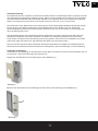
Tylö Elite Cloud Instrukcja obsługi
- Typ
- Instrukcja obsługi
Ten podręcznik jest również odpowiedni dla
- Control Panel Elite Cloud#hs_cos_wrapper_module_170083095099529 .icon-style--link .g-module-macros-icon { padding-left:8px; } #hs_cos_wrapper_module_170083095099529 .icon-style--link .g-module-macros-icon svg { fill:#C65622; }
- Control Panel Elite Cloud#hs_cos_wrapper_module_170083095099537 .icon-style--link .g-module-macros-icon { padding-left:8px; } #hs_cos_wrapper_module_170083095099537 .icon-style--link .g-module-macros-icon svg { fill:#C65622; }

Elite Cloud
Art. nr 2900 5208
2104
IPX5
SV
EN
DE
FR
NL
PL
RU

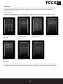
2 3
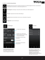
Monteringsanvisning och Quickstart guide Svenska sid 3
Installation Guide and Quickstart guide English page 10
Installationsanleitung und Schnellstartanleitung Deutsch Seite 17
Notice d’installation et Guide de démarrage rapide Français page 24
Installatiehandleiding en Snelstartgids Nederlands, pag. 31
Instrukcja instalacji i Pierwsze kroki Polski, stron 38
Руководство по монтажу Краткое руководство поначалу работы Русский язык стр. 45
SV

2 3
Monteringsanvisning
Manöverpanelen skall monteras i en frostfri omgivning.
Manöverpanelen kan installeras inne i eller utanför basturum/ångrum. Vid montering inne i basturum får den övre
kanten placeras högst 80 cm från golv och minst 30 cm från aggregatet. Omgivningstemperatur för manöverpanel
Elite Cloud får aldrig överstiga 80°C.
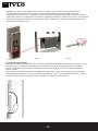
Montering på vägg kan göras med den medföljande konsolen eller med hjälp av medföljande dubbelsidiga
adhesiv. Om konsolen skall användas fästs manöverpanelen på konsolen med adhesiv.
För montering av manöverpanel direkt på vägg krävs ett genomgående hål på 30 mm.
Vid montering av panelen inne i ångrum skall montering ske direkt på vägg med medföljande adhesiv eller med
Tylös infällningsram (art. Nr 90001056). Väggen skall vara slät och väl rengjord efter håltagning (30 mm) innan
montering. Konsolen får inte användas.
Har du köpt Elite så kontrollera täckningen av ditt trådlösa nätverk innan du monterar fast manöverpanelen (se
även Kongurera: Systeminställningar i denna guide).
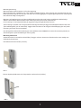
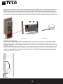
Montering med konsol
Använd konsolen för att markera skruvhålen på väggen. Skruva i skruvarna så att konsolen sitter stadigt men
fortfarande går att lossa.
Fäst adhesivet mot konsolen (se bild 1).
Bild 1
Ta bort skyddet på adhesivet och fäst panelen mot konsolen (se bild 2).
Bild 2
SV

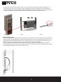
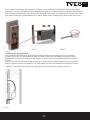
Fixera sladd och kontakt i konsolen (se bild 3 och 4). Tänk på att positionera kontakten enligt bild 5 så
att låstungan på RJ10 kommer uppåt (se bild 5). Montera upp panelen på väggen. Använd medföljande
manöverpanelsledning för att ansluta panelen till aggregatet. Ledningen går att korta om den är för lång och
använda medföljande extrakontakt. OBS det krävs specialtång för detta (crimptång för RJ10).
Bild 3 Bild 4 Bild 5
Montering utan konsol
Fäst det dubbelhäftande adhesivet på manöverpanelen. Innan panelen fästs mot vägg skall manöverpanelen
kopplas samman med aggregatet för kontroll att allt fungerar innan manöverpanelen permanent fästs mot
väggen. Därefter tas skyddet på adhesivet bort. Koppla därefter ihop manöverpanelen med ledningen, trä
genom kontakten genom hålet i väggen och tryck fast manöverpanelen mot väggen.
Vill man montera manöverpanelen utan konsol men behöver dra ledningen utanpå väggen kan följande
principlösning användas (Se bild 6). Detta gäller enbart för montering inne i bastu. Tänk på att hålet i väggen
där kontakten skall gå igenom måste vara minst 30 mm.
Bild 6
4 5
SV

Quickstart guide
För att du snabbt skall kunna komma igång och använda din nya bastu eller ditt nya ångrum så läs igenom
denna guide. Här beskrivs de grundläggande funktionerna som du behöver veta. Fullständig manual kan laddas
ned från https://www.tylohelo.com/sv/control-panel-tylo-elite.
Initial setup
Vid första start ställs vissa grundläggande parametrar in. Tryck på skärmen för att ange ditt val och därefter >
(eller <).
Flera andra parametrar ställs in automatiskt utifrån inställningarna ovan samt vilken typ av aggregat det är.
Samtliga parametrar kan ändras senare. De beskrivs i manualen.
4 5
SV
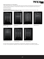
Välkomstskärm
(tryck på >)
Välj datumformat Ställ in datum Ställ in tid
Välj språk Välj region
Ange PIN kod: 8956
(tryck på )

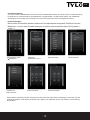
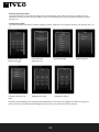
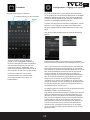
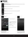
Overview
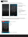
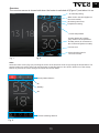
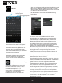
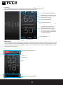
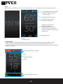
Overviewskärmen vissas både när aggregatet är avstängt (bild 7) och när det är igång (bild 8).
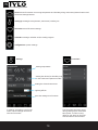
Bild 9
Home
Man kommer till Home skärmen (bild 9) genom att trycka på skärmen i Overview läge eller genom att trycka på
Home knappen. Aktivitetsknappar används för att starta och stänga av aggregatet. Även en Standby knapp visas.
När man trycker på aktivitetsknapparna ändrar de färg så att de visar aktuell status.
Aktivitets- / Statusknappar
På
Standby
Av
Funktions- / Inställningsknappar
6 7
SV
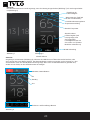
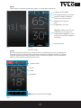
Inställd temperatur
Aktuell temperatur
Aktuell relativ luftfuktighet (visas
endast om temperatur/fuktsensor
är inkopplad på Combi och
Tylarium)
Aktuell tid
Återstående badtid
Vattennivå i tanken (gäller Combi)
Inställd luftfuktighet
Bild 7 Bild 8
Visar att panelen är ansluten till Wi

Home: Visar information om temperatur och fukt samt aktivitets-/statusknappar och Funktions-/
inställningsknappar.
Inställning: Inställning av temperatur, badtid, fukt mm.
Favoriter: Sparade favoritinställningar.
Kalender: Skapa kalender- och/eller veckoprogram.
Kongurera: Systeminställningar.
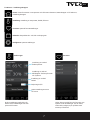
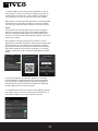
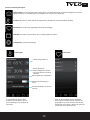
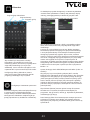
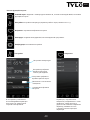
Funktions- / inställningsknappar
Inställningar
Inställning av önskad
badtemperatur
Inställning av önskad
luftfuktighet. Endast på Combi
och Tylarium.
Inställning av önskad
badtid.
Belysning Av/På
Spara inställningarna som
en favorit.
Favoriter
Under denna symbol nns de Favoriter som
sparats under inställningar. För att starta,
radera eller redigera, tryck på fältet med
namnet på favoriten.
Under inställningar ställs allt in för
badet. Dessa inställningar kan även
sparas till Favoriter.
6 7
SV

8
SV
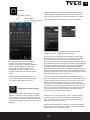
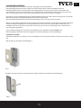
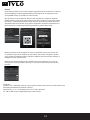
Kalender
För att man skall kunna använda Kalen-
derfunktionerna för Bastu- och Combi
aggregat samt även vid Tylarium anlägg-
ning krävs att en dörrkontakt kopplas till
dörren (Artikelnummer 90908035). Den
behövs även för att använda Wi till bas-
tu- och Combiaggregat.
Under kalender kan du skapa program för
enskilda datum eller program som åter-
kommer varje vecka.
Datumkalenderprogram
Dagprogram
Översikt program
Kongurera: Systeminställningar.
Under Kongurera nns både information om systemet och möj-
lighet att anpassa och ställa in olika funktioner och parametrar.
Man kan även kongurera eventuell tilläggsutrustning (som t ex
doftpumpar eller extra belysning).
När man trycker på Kongurera visar skärmen en meny med
olika indelningar. För att se er rader sätt ngret mot skärmen
och dra upp/ned.
I denna quickstart guide beskrivs endast menyn Wi, Network
och Cloud.
Under Network ansluter du till ditt bentliga WLAN. Tänk på att
platsen där manöverpanelen placeras påverkar hur bra den kan
nå trådlösa nätverk. Undersök signalstyrkan genom att, före
fast installation av manöverpanelen, starta systemet och gå in i
Network. Tillgängliga nätverk visas, och efter namnet visas en re-
lativ signalstyrka i %. Signalstyrkan måste vara minst 60% annars
måste en ny accesspunkt eller repeater sättas i närheten av Elite
panelen. Det lokala nätverket skall vara inställt på 2,4 GHz bandet
och Elite kan endast använda kanal 1-11.
Systemet stöder WPA/WPA2 personal SSID+Passord (max 20
tecken). För att ansluta mobilapplikation eller PC applikation se
instruktion för appar på TylöHelos hemsida (https://www.tylohelo.
com/sv/control-panel-tylo-elite).
Under Name kan du namnge ditt system. För att byta eller ändra
på namnet, tryck på namnet så kommer tangentbordet fram för
editering.
Elite Cloud ansluter automatiskt till valt nätverk om kontakten
förloras. Anslutningen visas genom att Wi symbolen tänds på
Home skärmen.
Anslutningen visas genom att Wi symbolen tänds på Home
skärmen.
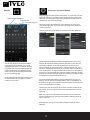
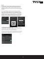
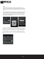
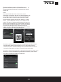
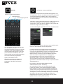
Cloud
Cloud
Cloud functionality
Pair your iOS/android device
Cloud Connection Status
Connected
Connect Device
Trusted Remote Devices

8 9
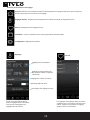
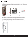
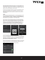
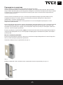
Cloud
Din Elite Cloud manöverpanel har blivit förregistrerad för
molnanslutning. Ladda ned appen från Apple Appstore eller
Google Play butiken. Aktivera Cloud anslutning genom att
trycka på Enable på Cloud skärmen (du måste först ansluta till
ditt Wi).
För att ansluta Elite Cloud till din enhet (iPhone, android),
öppna appen, gå till System/Network, tryck på Network och
välj Cloud. Gå tillbaka ett steg (<) och välj Add System. Tryck
därefter på Scan QR Code. Appen kommer be om tillgång till
kameran, acceptera detta. Gå därefter till Elite Cloud och tryck
på Connect device. En QR kod visas på panelen, scanna den
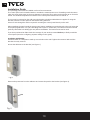
med appen. I manöverpanelen bekräftar du parkopplingen.
SV
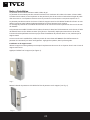
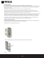
Du kan parkoppla er enheter till manöverpanelen samt även
radera tidigare parkopplade enheter.
För att radera en enhet, gå in på Trusted Remote Devices, välj
den som skall raderas och tryck på soptunnan.
Det är också möjligt att koppla din enhet till er system (bastu,
combi, ånga mm). Det är bara att repetera processen beskri-
ven ovan vid det nya systemet.
Connect Device
Connecting a Device
Scan the QR code b elow u sing you r Ty löHelo Contr ol
app to Pair to th is Elite Control Pan el
N2qdXv
01:22
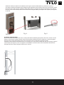
Cloud
Cloud functionality
Pair your iOS/android device
Cloud Connection Status
Connected
Connect Device
Trusted Remote Devices

Installation Guide
The operating panel must be installed in a frost-free environment.
The control panel can be installed inside or outside the sauna/steam room. If installing inside the sauna
cabin, the upper edge must not be more than 80 cm above the oor, and must be at least 30 cm from the
heater. The ambient temperature around the Pure control panel should never exceed 80 °C.
The unit can be mounted on the wall using the bracket or double-sided adhesive supplied. If using the
bracket, mount the control panel on the bracket using adhesive.
A 30 mm hole through the wall is required if mounting the control panel directly on the wall.
When installing the panel inside the steam room/sauna, installation must be directly to the wall, using the
accompanying adhesive or a Tylö embedding frame (item no. 90001056). The wall must be smooth and
perfectly clean after hole drilling (30 mm) before installation. The bracket must not be used.
If you have purchased an Elite check the coverage of your wireless network before you nally install the
control panel (see also Conguring: System settings in this guide).
Installation with bracket
Use the bracket as a template to mark up screw holes on the wall. Tighten the screws a little until the
bracket is loosely secured.
Secure the adhesive to the bracket (see Figure 1).
Fig. 1
Remove the protection from the adhesive and secure the panel to the bracket (see Figure 2).
Fig. 2
10
EN
11

10
Attach the cable and switch to the bracket (see Figures 3 and 4). Remember to position the switch in
accordance with the illustration (the locking tongue should be at the left side when seen from below). Install
the panel on the wall. Use the supplied control panel cable to connect the panel to the heater. If the cable is
too long, it can be shortened, then use the extra switch supplied. NB: special pliers are required (crimp pliers
for RJ10).
Fig. 3 Fig. 4 Fig. 5
Installation without bracket
Attach the double-sided adhesive to the control panel. Before attaching the panel to the wall, connect it to the
heater to check that everything works. Remove the protective backing from the adhesive. Connect the panel
wire, pass the contact through the hole in the wall and press the panel rmly against the wall.
If tting the panel without the bracket but it is necessary to run the cable outside the wall, the following solution
can be used (see Figure 6). This only applies to installation inside the sauna cabin. Remember that the hole
through which the contact will pass must be min. 30 mm.
Fig. 6
11
EN

Quickstart guide
In order to quickly get started and use your new sauna or steam room, read the whole of this guide. It describes
the basic operations that you need to know. The complete manual can be downloaded from https://www.tylohelo.
com/en/control-panel-tylo-elite.
.
Initial set-up
At the rst start, certain basic parameters are set. Touch the screen to indicate your choice and then > (or <).
Several other parameters are set automatically on the basis of the above settings, and the type of heater. Any of
the parameters can be altered later. They are described in the manual.
Welcome screen
(touch >)
Select the date format Set the date:Set the time:
Select language Select region
12
EN
Enter PIN: 8956
(touch )
13

12
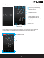
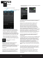
Overview
The overview screen is shown both when the heater is switched o (Figure 7) and when it is on
Temperature setting
Current temperature
Current relative air humidity
(only shown if the temperature/
humidity sensor is connected on
the Combi and Tylarium models)
Current time
Remaining sauna time
Water level in the tank (applies to
the Combi model)
Air humidity setting
Fig. 7 Fig. 8
Fig. 9
Home
Get to the Home screen (g. 9) by touching the screen in the Overview mode or by pressing the Home button. The
Activity buttons are used to start and stop the heater. A Standby button is also shown. When one of the activity
buttons is pressed, the colour changes to indicate the current status.
Activity/Status buttons
On
Standby:
O
Functions/Settings buttons
Shows that the panel is
connected to Wi.
13
EN

Home: Show information concerning temperature and humidity, along with activity/status buttons and
Functions/settings buttons.
Setting up: Setting the temperature, sauna time, humidity, etc.
Favourites: Saved favourite settings.
Calendar: Creating a calendar and/or weekly program.
Conguration: System settings.
Functions/Settings buttons
Settings
Setting temperature
Setting the desired air humidity. Only
on the Combi and Tylarium models.
Setting the desired sauna time.
Lighting Off/On
Save the settings as a favourite.
Favourites
The Favourites that were saved
during setting up are saved with
this symbol. In order to start,
delete or edit, press on the eld
with the name of the favourite.
In settings, everything is set for the
sauna. These settings can also be
saved to Favourites.
14
EN

14
Calender
In order to be able to use the Calendar
functions for the Sauna and Combi
heaters, and also the Tylarium installation,
a door switch is required for EU region,
connected to the door (Tylö part no.
90908035). It is also needed in order to
use WiFi with a sauna heater and Combi
heater.
While setting the calendar function you
can create programs for individual dates
or programs that repeat every week.
Date and calendar program
Day program
Overview program
Conguration: System settings.
When Conguration is touched, the screen shows a menu
with a number of separate sections. IN order to see more
rows, put your nger on the screen and draw it up or down.
Only the Wi menu is described in this quickstart guide.
In order to be able to use Wi for the sauna and Combi
installation, a door switch must be connected.
You connect to your WLAN under the Network menu. Bear
in mind that the position where the control panel is located
affects how well it can communicate with the wireless
network. Many kinds of material disturb the wi signal. Before
xed installation of the control panel, check the signal strength.
To do this, start the system and go into Network. Available
networks will be displayed with a relative signal strength
indicated in % after each name. The signal strength must be at
least 60%. Otherwise a new access point or repeater must be
installed near the Elite panel. The local network must be set on
the 2.4 GHz band and only on channel 1-11.
The system supports WPA/WPA2 personal SSID+password
(max. 20 characters). In order to connect to your local network,
rst activate Wi and press Network. Then press Scan which
searches for the accessible networks. In order to connect,
press on the desired network; if a password is required press
on Password, enter the password and then press Connect. In
order to connect mobile applications or PC applications refer
to the app instructions on the Tylö web site (https://www.
tylohelo.com/en/control-panel-tylo-elite).
Under Name you can name your system. A default name is
present to begin with, and this depends on the system you
have. In order to change or alter the name, press it and a
keyboard will appear for editing.
Elite Cloud automatically re-connects to the selected WLAN
if connection is lost. When the system is connected, the WiFi
symbol lights up on the Home screen.
During Conguration there is both information
about the system and the possibility to adapt
and set various functions and parameters. It is
also possible to congure additional equipment
(such as for example fragrance pumps or extra
lighting).
15 15
EN

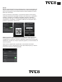
Cloud
Your Elite Cloud control panel has been pre-registred for cloud
connection. Download the app from Apple Appstore or the Google
Play shop. After connecting to your WLAN press Enable on the Cloud
menu.
To pair your device (iPhone or android device)open the app and go to
System/Network and select Cloud. Press < and select Add System.
Press Scan QR code. On Elite Cloude Control Panel press Connect
device. A QR code will be displayed. Scan the code and accept the
the pairing in the Elite Cloud.
Cloud
Cloud functionality
Pair your iOS/android device
Cloud Connection Status
Connected
Connect Device
Trusted Remote Devices
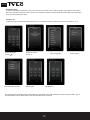
Connect Device
Connecting a Device
Scan the QR code b elow u sing you r Ty löHelo Contr ol
app to Pair to th is Elite Control Pan el
N2qdXv
01:22
You can pair many devices to your Elite Cloud and also delete old pai-
red devices. To delete a paired device press Trusted Remote Devices
and select the device to be deleted, then press the trash bin symbol.
It is also possible to connect your device to multiple systems (e.g.
Sauna, Combi heater, steam etc.). Just repeat the process described
above.
16 17
EN

DE
Installationsanleitung
Die Steuertafel muss im frostfreien Innenbereich installiert werden. Das Bedienpanel kann entweder innerhalb
oder außerhalb der Saunakabine installiert werden. Wenn es innen installiert wird, sollte sich die obere Kante
nicht mehr als 80 Zentimeter über dem Boden benden und mindestens einen 30-cm-Abstand zur Heizung
haben. Die Umgebungstemperatur der Pure-Steuertafel zu keiner Zeit den Wert von 80 °C überschreiten.
Das Gerät kann an der Wand mittels einer Halterung oder eines doppelseitigen Klebebands befestigt werden.
Bei Verwendung der Halterung befestigen Sie das Bedienpanel an der Halterung mit dem Klebeband.
Soll das Bedienpanel direkt an der Wand montiert werden, ist dazu ein 30mm breites Loch notwendig, das
durch die Wand gebohrt wird.
Falls das Bedienpanel in der Schwitzkabine/Sauna angebracht wird, sollte es direkt an der Wand mit dem
mitgelieferten Klebeband oder dem speziellen Tylö Rahmen zur Einbettung (Artikelnummer 90001056)
xiert werden. Die Wand sollte nach Bohrung des 30mm großen Loches und vor der Installation des Geräts
vollkommen glatt und sauber sein. Die Halterung darf dabei nicht verwendet werden.
Wenn Sie ein Elite erworben haben, überprüfen Sie vor der letztendlichen Installation des Bedienpanels die
Reichweite Ihres drahtlosen Netzwerks (siehe auch Konguration: Systemeinstellungen in dieser Anleitung).
Installation mit Halterung
Verwenden Sie die Halterung, um die Bohrlöcher an der Wand zu markieren. Drehen Sie die Schrauben erst nur
ein wenig ein, sodass die Halterung locker gesichert ist.
Bringen Sie das Klebeband an der Halterung an (siehe Abbildung 1).
Abbildung 1
Entfernen Sie den Klebschutz und befestigen Sie das Panel an der Halterung (siehe Abbildung 2).
Abbildung 2
16 17

Befestigen Sie das Kabel und den Schalter an der Halterung (siehe Abbildung 3 und 4). Vergewissern Sie sich, den
Schalter genau in Übereinstimmung mit der Abbildung zu positionieren (die Rastzunge sollte sich von unten her
gesehen links benden). Installieren Sie das Panel an der Wand. Verwenden Sie dazu das mitgelieferte Kabel und
verbinden Sie das Panel mit der Heizung. Falls das Kabel zu lang ist, kann es gekürzt werden. Verwenden Sie dann
den zusätzlich mitgelieferten Schalter. Anmerkung: Spezielle Zangen sind dazu notwendig (Crimp-Zangen für RJ10).
Abbildung 3 Abbildung 4 Abbildung 5
Installation ohne Halterung
Bringen Sie das doppelseitige Klebeband am Bedienpanel an. Bevor Sie dann das Panel an der Wand befestigen,
verbinden Sie es mit der Heizung, um zu überprüfen, ob alles funktioniert. Entfernen Sie die Schutzschicht vom
Klebeband. Verbinden Sie das Panelkabel, stecken Sie es durch das Loch in der Wand und pressen dann das Panel
fest gegen die Wand.
Wenn das Panel ohne Halterung montiert wird, es aber notwendig ist, dass das Kabel an der Außenseite der Wand
verlaufen soll, kann folgende Lösung verwendet werden (siehe Abbildung 6). Das trifft nur auf eine Installation im
Inneren der Saunakabine zu. Vergewissern Sie sich, dass das Loch, durch welches das Kabel durchgesteckt wird,
mindestens 30mm breit sein muss.
Abbildung 6
18 19
DE

18
Schnellstartanleitung
Um rasch mit der Inbetriebnahme Ihrer Sauna oder Schwitzkabine starten zu können, lesen Sie diese Anleitung
komplett durch. Sie beschreibt die grundlegenden Vorgangsweisen, die Sie wissen sollten. Die vollständige
Anleitung kann unter https://www.tylohelo.com/de/control-panel-tylo-elite heruntergeladen werden.
Erstinbetriebnahme
Beim ersten Einschalten werden bestimmte Grundparameter eingestellt. Berühren Sie den
Bildschirm, um sich Ihre Auswahl anzeigen zu lassen,und verwenden dann die Symbole >
(oder <).
Einige andere Parameter werden automatisch anhand der oben genannten Einstellungen und an den Typ der
Heizung angepasst. Jeder dieser Parameter kann später noch geändert werden. Sie werden in der Anleitung
beschrieben.
Startseite
(drücken Sie auf >)
Auswahl des
Datumformats
Datum einstellen Uhrzeit einstellen
Sprachauswahl Länderauswahl
19
DE
PIN eingeben: 8956
( berühren)

Übersicht
Die Übersichtsseite wird sowohl angezeigt, wenn die Heizung ausgeschaltet (Abbildung 7) als auch eingeschaltet
ist (Abbildung 8).
Abbildung 7 Abbildung 8
Abbildung 9
Startseite
Sie gelangen zur Startseite (Abbildung 9), indem Sie den Bildschirm im Übersichtsmodus berühren, oder
wenn Sie auf den Home Button drücken. Die Aktivitäts-Buttons werden verwendet, um die Heizung ein- oder
auszuschalten. Auch ein Standby-Button wird angezeigt. Wenn einer der Aktivitäts-Buttons gedrückt wird,
ändert sich die Farbe, um den aktuellen Status anzuzeigen.
Aktivitäts-/Status-Buttons
Ein
Standby:
Aus
Funktions- und Einstellungs-Buttons
20
DE
Temperatureinstellung
Aktuelle Temperatur
Aktuelle relative
Luftfeuchtigkeit (wird
nur angezeigt, wenn
der Temperatur-/
Feuchtigkeitssensor mit
den Combi- und Tylarium-
Modellen verbunden ist)
Aktuelle Uhrzeit
Verbleibende Sitzungsdauer
Wasserstand im Tank (gilt
für das Combi-Modell)
Einstellung der
Luftfeuchtigkeit
WLAN-Verbindung
21
Strona jest ładowana ...
Strona jest ładowana ...
Strona jest ładowana ...
Strona jest ładowana ...
Strona jest ładowana ...
Strona jest ładowana ...
Strona jest ładowana ...
Strona jest ładowana ...
Strona jest ładowana ...
Strona jest ładowana ...
Strona jest ładowana ...
Strona jest ładowana ...
Strona jest ładowana ...
Strona jest ładowana ...
Strona jest ładowana ...
Strona jest ładowana ...
Strona jest ładowana ...
Strona jest ładowana ...
Strona jest ładowana ...
Strona jest ładowana ...
Strona jest ładowana ...
Strona jest ładowana ...
Strona jest ładowana ...
Strona jest ładowana ...
Strona jest ładowana ...
Strona jest ładowana ...
Strona jest ładowana ...
Strona jest ładowana ...
Strona jest ładowana ...
Strona jest ładowana ...
Strona jest ładowana ...
-
 1
1
-
 2
2
-
 3
3
-
 4
4
-
 5
5
-
 6
6
-
 7
7
-
 8
8
-
 9
9
-
 10
10
-
 11
11
-
 12
12
-
 13
13
-
 14
14
-
 15
15
-
 16
16
-
 17
17
-
 18
18
-
 19
19
-
 20
20
-
 21
21
-
 22
22
-
 23
23
-
 24
24
-
 25
25
-
 26
26
-
 27
27
-
 28
28
-
 29
29
-
 30
30
-
 31
31
-
 32
32
-
 33
33
-
 34
34
-
 35
35
-
 36
36
-
 37
37
-
 38
38
-
 39
39
-
 40
40
-
 41
41
-
 42
42
-
 43
43
-
 44
44
-
 45
45
-
 46
46
-
 47
47
-
 48
48
-
 49
49
-
 50
50
-
 51
51


Tylö Elite Cloud Instrukcja obsługi
- Typ
- Instrukcja obsługi
- Ten podręcznik jest również odpowiedni dla
-
- Control Panel Elite Cloud#hs_cos_wrapper_module_170083095099529 .icon-style--link .g-module-macros-icon { padding-left:8px; } #hs_cos_wrapper_module_170083095099529 .icon-style--link .g-module-macros-icon svg { fill:#C65622; }
- Control Panel Elite Cloud#hs_cos_wrapper_module_170083095099537 .icon-style--link .g-module-macros-icon { padding-left:8px; } #hs_cos_wrapper_module_170083095099537 .icon-style--link .g-module-macros-icon svg { fill:#C65622; }
w innych językach
- Deutsch: Tylö Elite Cloud Bedienungsanleitung
- svenska: Tylö Elite Cloud Bruksanvisning
- français: Tylö Elite Cloud Le manuel du propriétaire
- English: Tylö Elite Cloud Owner's manual
- Nederlands: Tylö Elite Cloud de handleiding
Powiązane dokumenty
-
Tylö Tylarium#hs_cos_wrapper_module_170083095099530 .icon-style--link .g-module-macros-icon { padding-left:8px; } #hs_cos_wrapper_module_170083095099530 .icon-style--link .g-module-macros-icon svg { fill:#C65622; } Instrukcja obsługi
-
-
-
-
-
-
-