Hitachi RAS-80YHA4 Summary Of Troubleshooting Method
- Typ
- Summary Of Troubleshooting Method

-
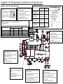
SUMMARY OF TROUBLESHOOTING METHOD FOR INDOOR UNIT
MODEL : RAS-70YHA4~80YHA4
Checking the connection of 1, 2, 3 terminal to the indoor.
1) Power ON the unit.
2) After around 1 minute, check the AC voltage between terminal as below table.
Connection condition
Terminal 1 no connection
Terminal 2 no connection
Terminal 3 no connection
All connection OK
Voltage value between terminal Outdoor LD301
indication
1 to 2 2 to 3 1 to 3
240V
240V
240V
240V
0.1-0.4V
100 - 120V
0.1-0.4V
around 0.3V
240V
120-140V
240V
240V
9 times blink
9 times blink
9 times blink
Off or 1 time blink
Checking the Heat Exchanger thermistor.
1) Power off the unit.
2) Disconnect the thermistor wire from
CN4 of MAIN P.W.B.
3) Check the resistance value between
the wire of thermistor.
It shall be around 10kΩ ± 1kΩ.
Checking the horizontal stepping motor.
1) Power off the unit.
2) Disconnect the thermistor wire from
CN11 or 14 of MAIN P.W.B.
3) Check the resistance value between
pin 1 and 5.
It shall be around 195 ± 5Ω.
Checking the vertical stepping motor.
1) Power off the unit.
2) Disconnect the thermistor wire from
CN12 of MAIN P.W.B.
3) Check the resistance value between
pin 1 and 5.
It shall be around 195 ± 5Ω.
Checking the Room temperature thermistor.
1) Power off the unit.
2) Disconnect the thermistor wire from
CN2 of Indicating P.W.B
3) Check the resistance value between
the lead of thermistor.
It shall be around 10kΩ ± 1kΩ.
Checking all the fuse continuity.
There are 1 fuses inside the MAIN
P.W.B.
1) Power off the unit.
2) Check the continuity of FU1 fuse:
It shall be (3.15A) .
Checking the Terminal fuse continuity.
1) Power off the unit.
2) Disconnect the thermistor wire from
CN3 of MAIN P.W.B
3) Check the resistance value between
the wire.
It shall be almost 0Ω.
Fan Motor Check
(+) Red (Pin1) &
(-) Black(Pin4)
(+) White (Pin5) &
(-) Black(Pin4)
(+) Yellow (Pin6) &
(-) Black(Pin4)
(+) Blue (Pin7) &
(-) Black(Pin4)
(+) Positive probe (-) Negative probe
Resistance
> 2MΩ/OL 360VDC
35kΩ~40kΩ 15VDC
230kΩ~250kΩ 3~6VDC
> 2MΩ/OL 7.5VDC
CN16
( - side of multimeter probe)
( + side of multimeter probe)
Test Run
1) Power ON the unit and
wait for 3 seconds.
2) Press and hold temp.
switch for 5 seconds or
longer.
Operation

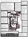
Checking the compressor
motor winding.
1) Power off the unit.
2) Disconnect compressor
wire connector between
compressor to IPM P.W.B.
3) Check the resistance
value between WHT, YEL,
RED wire of compressor
wire. It shall be same on all
terminals between 1Ω to 3Ω.
Checking the IPM IC of IPM P.W.B.
1) Power off the unit.
2) Disconnect compressor wire connector between
compressor to IPM P.W.B.
3) Check the diode value between below point :-
a) Terminal U, V, W (+ side of multimeter probe) to
Terminal P (WHT wire) ( - side of multimeter probe).
It shall be around 0.40 to 0.43.
b) Terminal N (BLK wire) (+ side of multimeter probe) to
Terminal U, V, W ( - side of multimeter probe)
It shall be around 0.40 to 0.43.
**During normal running, DC voltage between below point are:-
a) Terminal P & Terminal N shall be around 320V
b) Terminal U, V, W (+ side of multimeter probe) to Terminal N
( - side of multimeter probe) shall be around 160V.
Checking the reactor winding.
1) Power off the unit.
2) Disconnect YEL and BRN
wire at TAB3 and TAB4 from
MAIN P.W.B.
3) Check the resistance value
between YEL & BRN wire of
reactor. It shall be around
0.01Ω to 0.1Ω.
** During normal running, DC
voltage between TAB 3 and
TAB4 shall be 17V to 20V.
Checking the fan motor
winding.
1) Power off the unit.
2) Disconnect fan motor wire
from CN24 of MAIN P.W.B.
3) Check the resistance value
between RED, WHT, BLK
wire of fan motor. It shall
be around 20Ω to 50Ω.
**During normal running, DC
voltage between RED, WHT,
BLK wire of fan motor (+ side
of multimeter probe) to
Terminal N (R741 leg) (- side
of multimeter probe) shall
be around 160V.
Checking all the fuse continuity.
There are 5 fuses inside the MAIN
P.W.B.
1) Power off the unit.
2) Check the continuity of below fuse:
a) F1 (25A) b) F5 (3.15A)
c) F6 (3.15A) d) F3 (3A)
e) F4 (2A)
Checking the power source.
1) Power ON the unit.
2) Check the AC voltage from power
source between terminal L and N.
It shall be around 240 ±10 V
Checking the connection of 1, 2, 3 terminal to the indoor.
1) Power ON the unit.
2) After around 1 minute, check the AC voltage between terminal as below table.
Connection condition
Terminal 1 no connection
Terminal 2 no connection
Terminal 3 no connection
All connection OK
Voltage value between terminal Outdoor LD301
indication
1 to 2 2 to 3 1 to 3
240V
240V
240V
240V
0.1-0.4V
100 - 120V
0.1-0.4V
around 0.3V
240V
120-140V
240V
240V
9 times blink
9 times blink
9 times blink
Off or 1 time blink
Checking the expansion
valve winding.
1) Power off the unit.
2) Disconnect the
expansion valve from
CN15 of MAIN P.W.B.
3) Check the resistance
value between wire of
expansion valve as
below:-
a) WHT to BRN
b) ORN to BRN
c) YEL to RED
d) BLU to RED
It shall be around
46Ω ± 3.7Ω.
Checking the reversing
valve winding.
1) Power off the unit.
2) Disconnect the reversing
valve wire from CN2 of
MAIN P.W.B.
3) Check the resistance
value between the wire
of reversing valve.
It shall be around
1.9kΩ.
Checking the outdoor
temperature thermistor.
1) Power off the unit.
2) Disconnect the
thermistor wire from
CN10 of MAIN P.W.B.
3) Check the resistance
value between the
wire of thermistor.
It shall be around
1.7kΩ ± 0.3kΩ.
Checking the defrost
thermistor.
1) Power off the unit.
2) Disconnect the
thermistor wire from
CN9 of MAIN P.W.B.
3) Check the resistance
value between the
wire of thermistor.
It shall be around
1.7kΩ ± 0.3kΩ.
Checking the OH thermistor.
1) Power off the unit.
2) Disconnect the thermistor wire from
CN8 of MAIN P.W.B.
3) Check the resistance value between
the wire of thermistor.
It shall be around 25kΩ ± 5kΩ.
SUMMARY OF TROUBLESHOOTING METHOD FOR OUTDOOR UNIT
MODEL : RAC-70YHA4 AND RAC-80YHA4
Test Run
1) Remove Terminal 3
connection.
2) Power ON the unit and
wait for 30 seconds.
3) Press and hold test
switch for 5 seconds.
-
 1
1
-
 2
2


Hitachi RAS-80YHA4 Summary Of Troubleshooting Method
- Typ
- Summary Of Troubleshooting Method
w innych językach
- English: Hitachi RAS-80YHA4
Inne dokumenty
-
AcuityBrands sPODMA D Instrukcja obsługi
-
Suzuki GRAND VITARA - Instrukcja obsługi
-
 Hach pHD Sensor Instrukcja obsługi
-
Sea Ray 2005 420DA Parts Manual
-
-
-
-
-
Chamberlain LiftMaster CB124 Instrukcja obsługi
-
