
USER´S MANUAL
BEDIENUNGSANLEITUNG
MANUEL D’UTILISATION
MANUAL DE USUARIO
INSTRUKCJA OBSŁUGI
MANUALE UTENTE
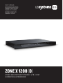
ZONE X 1208
(
D
)
HYBRID ARCHITECTURE DSP MATRIX - 12 IN / 8 OUT
LDZONEX1208, LDZONEX1208D

CONTENTS / INHALTSVERZEICHNIS / TABLE DES MATIÈRES / INDICE / SPIS TREŚCI / INDICE
ENGLISH
SAFETY INFORMATION 3
FEATURES 5
PACKAGING CONTENT 5
CONNECTIONS, CONTROLS AND DISPLAY ELEMENTS 5
CONNECTING DEVICES 6
XILICA DESIGNER SOFTWARE 8
STARTING THE SOFTWARE 10
NETWORK VIEW 10
FIRMWARE UPGRADE 11
FIRMWARE UPGRADE PROCEDURE 11
PROJECT VIEW 14
DESIGN 15
ONLINE MODE 18
GPI/O - CONNECTION EXAMPLES 24
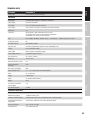
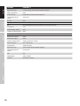
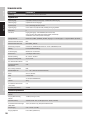
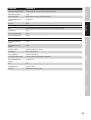
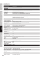
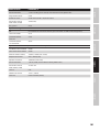
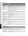
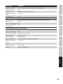
TECHNICAL DATA 25
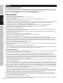
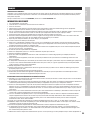
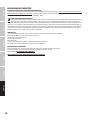
MANUFACTURER´S DECLARATIONS 27
DEUTSCH
SICHERHEITSHINWEISE 28
EIGENSCHAFTEN 30
LIEFERUMFANG 30
ANSCHLÜSSE, BEDIEN- UND ANZEIGEELEMENTE 30
GERÄTE VERBINDEN 31
XILICA DESIGNER-SOFTWARE 33
SOFTWARE STARTEN 35
NETWORK VIEW 35
FIRMWARE-UPGRADE 36
FIRMWARE-UPGRADE DURCHFÜHREN 36
PROJECT VIEW 39
DESIGN 40
ONLINE-BETRIEB 43
GPI/O – ANSCHLUSSBEISPIELE 49
TECHNISCHE DATEN 50
HERSTELLERERKLÄRUNGEN 52
FRANÇAIS
INFORMATIONS DE SÉCURITÉ 53
CARACTÉRISTIQUES 55
CONTENU DE L’EMBALLAGE 55
CONNEXIONS, DISPOSITIFS DE COMMANDE ET D’AFFICHAGE 55
CONNEXION DES APPAREILS 56
LOGICIELXILICADESIGNER 58
DÉMARRAGE DU LOGICIEL 60
VUE RÉSEAU 60
MISE À NIVEAU DU MICROLOGICIEL 61
PROCÉDURE DE MISE À NIVEAU DU MICROLOGICIEL 61
VUE PROJET 64
CONCEPTION 65
MODE EN LIGNE 68
EXEMPLESDECONNEXIONDESPORTSGPIO 74
CARACTÉRISTIQUES TECHNIQUES 75
DÉCLARATIONS DU FABRICANT 77
ESPAÑOL
INFORMACIÓN DE SEGURIDAD 78
CARACTERISTICAS 80
CONTENIDO DEL PAQUETE 80
CONEXIONES, CONTROLES Y ELEMENTOS DE VISUALIZACIÓN 80
DISPOSITIVOS DE CONEXIÓN 81
SOFTWARE XILICA DESIGNER 83
INICIO DEL SOFTWARE 85
VISTA DE RED 85
ACTUALIZACIÓN DEL FIRMWARE 86
PROCEDIMIENTO DE ACTUALIZACIÓN DEL FIRMWARE 86
VISTA DE PROYECTO 89
DISEÑO 90
MODO ONLINE 93
EJEMPLOS DE CONEXIÓN DE GPI/O 99
DATOS TÉCNICOS 100
DECLARACIONES DEL FABRICANTE 102
POLSKI
INFORMACJEDOTYCZĄCEBEZPIECZEŃSTWA 103
WŁAŚCIWOŚCI 105
ZAWARTOŚĆZESTAWU 105
PODŁĄCZENIE,KONTROLKIIWYŚWIETLANEELEMENTY 105
PODŁĄCZANIEURZĄDZEŃ 106
OPROGRAMOWANIE XILICA DESIGNER 108
URUCHAMIANIE OPROGRAMOWANIA 110
WIDOK SIECIOWY 110
AKTUALIZACJAOPROGRAMOWANIAUKŁADOWEGO 111
PROCEDURAAKTUALIZACJIOPROGRAMOWANIAUKŁADOWEGO 111
WIDOK PROJEKTU 114
DESIGN 115
TRYB ONLINE 118
GPI/O–PRZYKŁADOWEPODŁĄCZENIA 124
DANE TECHNICZNE 125
OŚWIADCZENIAPRODUCENTA 127
ITALIANO
INFORMAZIONI SULLA SICUREZZA 128
CARATTERISTICHE 130
CONTENUTO DELLA CONFEZIONE 130
COLLEGAMENTI, CONTROLLI ED ELEMENTI DEL DISPLAY 130
COLLEGAMENTO DI DISPOSITVI 131
SOFTWARE XILICA DESIGNER 133
AVVIO DEL SOFTWARE 135
NETWORK VIEW 135
AGGIORNAMENTO DEL FIRMWARE 136
PROCEDURA DI AGGIORNAMENTO DEL FIRMWARE 136
PROJECT VIEW 139
DESIGN 140
MODALITÀ ONLINE 143
GPI/O - ESEMPI DI COLLEGAMENTI 149
DATI TECNICI 150
DICHIARAZIONI DEL PRODUTTORE 152

3
ENGLISH
YOU‘VE MADE THE RIGHT CHOICE!
We have designed this product to operate reliably over many years. LD Systems stands for this with its name and many years of experience as
a manufacturer of high-quality audio products. Please read this User‘s Manual carefully, so that you can begin making optimum use of your LD
Systems product quickly.
YoucanndmoreinformationaboutLD-SYSTEMS at our Internet site WWW.LD-SYSTEMS.COM
SAFETY INFORMATION
1. Please read these instructions carefully.
2. Keep all information and instructions in a safe place.
3. Follow the instructions.
4. Observe all safety warnings. Never remove safety warnings or other information from the equipment.
5. Use the equipment only in the intended manner and for the intended purpose.
6. Use only sufficiently stable and compatible stands and/or mounts (for fixed installations). Make certain that wall mounts are properly installed
and secured. Make certain that the equipment is installed securely and cannot fall down.
7. During installation, observ e the applicable safety regulations for your country.
8. Never install and operate the equipment near radiators, heat registers, ovens or other sources of heat. Make certain that the equipment is
always installed so that is cooled sufficiently and cannot overheat.
9. Never place sources of ignition, e.g., burning candles, on the equipment.
10. Ventilation slits must not be blocked.
11. Do not use this equipment in the immediate vicinity of water (does not apply to special outdoor equipment - in this case, observe the special
instructions noted below. Do not expose this equipment to flammable materials, fluids or gases. Avoid direct sunlight!
12. Make certain that dripping or splashed water cannot enter the equipment. Do not place containers filled with liquids, such as vases or drinking
vessels, on the equipment.
13. Make certain that objects cannot fall into the device.
14. Use this equipment only with the accessories recommended and intended by the manufacturer.
15. Do not open or modify this equipment.
16. After connecting the equipment, check all cables in order to prevent damage or accidents, e.g., due to tripping hazards.
17. During transport, make certain that the equipment cannot fall down and possibly cause property damage and personal injuries.
18. If your equipment is no longer functioning properly, if fluids or objects have gotten inside the equipment or if it has been damaged in anot
her way, switch it off immediately and unplug it from the mains outlet (if it is a powered device). This equipment may only be repaired by
authorized, qualified personnel.
19. Clean the equipment using a dry cloth.
20. Comply with all applicable disposal laws in your country. During disposal of packaging, please separate plastic and paper/cardboard.
21. Plastic bags must be kept out of reach of children.
22. Please note that changes or modifications not expressly approved by the party responsible for compliance could void the user´s
authority to operate the equipment.
FOR EQUIPMENT THAT CONNECTS TO THE POWER MAINS
23. CAUTION: If the power cord of the device is equipped with an earthing contact, then it must be connected to an outlet with a protective ground.
Never deactivate the protective ground of a power cord.
24. If the equipment has been exposed to strong fluctuations in temperature (for example, after transport), do not switch it on immediately.
Moisture and condensation could damage the equipment. Do not switch on the equipment until it has reached room temperature.
25. Before connecting the equipment to the power outlet, first verify that the mains voltage and frequency match the values specified on the
equipment. If the equipment has a voltage selection switch, connect the equipment to the power outlet only if the equipment values and the
mains power values match. If the included power cord or power adapter does not fit in your wall outlet, contact your electrician.
26. Do not step on the power cord. Make certain that the power cable does not become kinked, especially at the mains outlet and/or power adapter
and the equipment connector.
27.
When connecting the equipment, make certain that the power cord or power adapter is always freely accessible. Always disconnect the equipment
from the power supply if the equipment is not in use or if you want to clean the equipment. Always unplug the power cord and power adapter from
the power outlet at the plug or adapter and not by pulling on the cord. Never touch the power cord and power adapter with wet hands.
28.
Whenever possible, avoid switching the equipment on and off in quick succession because otherwise this can shorten the useful life of the equipment.
29. IMPORTANT INFORMATION: Replace fuses only with fuses of the same type and rating. If a fuse blows repeatedly, please contact an authorised
service centre.
30. To disconnect the equipment from the power mains completely, unplug the power cord or power adapter from the power outlet.
31. If your device is equipped with a Volex power connector, the mating Volex equipment connector must be unlocked before it can be removed.
However, this also means that the equipment can slide and fall down if the power cable is pulled, which can lead to personal injuries and/or
other damage. For this reason, always be careful when laying cables.
32. Unplug the power cord and power adapter from the power outlet if there is a risk of a lightning strike or before extended periods of disuse.
33. The appliance is not to be used by persons (including children) with reduced physical, sensory or mental capabilities, or lack of experience
and knowledge.
34. Children must be instructed not to play with the device.
35. If the power cord of the device is damaged, do not use the device. The power cord must be replaced by an adequate cable or assembly from an
authorized service center.
DEUTSCH ENGLISHFRANÇAISESPAÑOLPOLSKIITALIANO

4
FEATURES
• Hybrid architecture DSP processor
• DSP templates available for different installation requirements
• 40-bit floating point DSP engine with analog devices dual core SHARC+ and ARM Cortex A5 processor
• New generation Linux operating system
• Premium grade microphone preamps and high-performance 32 bit AD/DA converters
• 12 balanced mic/line inputs with 48V phantom power selection per input
• 8 balanced outputs
• 8 GPI and 8 GPO logic ports
• 6-pole terminal block connectors (pitch 3.81 mm) for all audio and control inputs/outputs
• REMOTE bus for integration with wall panels and paging microphones from LD Systems
• Clean and intuitive front panel design
• Ethernet interface for remote control via the universal control software Xilica Designer
• Remote control apps available in both iOS and Android, for custom user panels
• Integrated event scheduler
• Optional 64x64 Dante expansion (audio over IP connectivity)
• 19” rack device, 1 RU
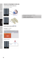
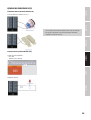
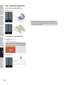
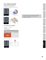
PACKAGING CONTENT
• LD ZoneX hardware
• Power cable
• User manual
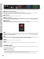
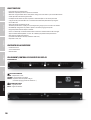
CONNECTIONS, CONTROLS AND DISPLAY ELEMENTS
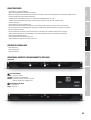
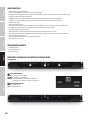
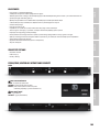
FRONT
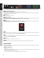
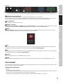
1
GLOBAL STATUS LEDS
POWER = device is powered on
NETWORK = network connection established
REMOTE = LD Systems remote devices connected
(paging microphones, control panels, etc)
2
INPUT & OUTPUT LEDS
White = Signal present
Red = Signal overdriven
2
1
2
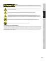
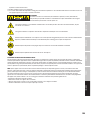
CAUTION:
To reduce the risk of electric shock, do not remove cover (or back). There are no user serviceable parts
inside. Maintenance and repairs should be exclusively carried out by qualified service personnel.
The warning triangle with lightning symbol indicates dangerous uninsulated voltage inside the unit, which may cause an
electrical shock.
The warning triangle with exclamation mark indicates important operating and maintenance instructions.
Warning! This symbol indicates a hot surface. Certain parts of the housing can become hot during operation. After use, wait for a
cool-down period of at least 10 minutes before handling or transporting the device.
Warning! This device is designed for use below 2000 metres in altitude.
Warning! This product is not intended for use in tropical climates.
CAUTION! HIGH VOLUMES IN AUDIO PRODUCTS!
This device is meant for professional use. Therefore, commercial use of this equipment is subject to the respectively applicable national accident
prevention rules and regulations. As a manufacturer, Adam Hall is obligated to notify you formally about the existence of potential health risks.
Hearing damage due to high volume and prolonged exposure: When in use, this product is capable of producing high sound-pressure levels (SPL)
that can lead to irreversible hearing damage in performers, employees, and audience members. For this reason, avoid prolonged exposure to
volumes in excess of 90 dB.
NOTE: This equipment has been tested and found to comply with the limits for a Class B digital device, pursuant to Part 15 of the FCC
Rules. These limits are designed to provide reasonable protection against harmful interference in a residential installation. This equipment genera-
tes, uses and can radiate radio frequency energy and, if not installed and used in accordance with the instructions, may cause
harmful interference to radio communications. However, there is no guarantee that interference will not occur in a particular installation. If this
equipment does cause harmful interference to radio or television reception, which can be determined by turning the equipment off and on, the
user is encouraged to try to correct the interference by one or more of the following measures:
– Reorient or relocate the receiving antenna.
– Increase the separation between the equipment and receiver.
– Connect the equipment into an outlet on a circuit different from that to which the receiver is connected.
– Consult the dealer or an experienced radio/TV technician for help.
DEUTSCHENGLISH
FRANÇAIS
ESPAÑOL
POLSKI
ITALIANO

5
FEATURES
• Hybrid architecture DSP processor
• DSP templates available for different installation requirements
• 40-bit floating point DSP engine with analog devices dual core SHARC+ and ARM Cortex A5 processor
• New generation Linux operating system
• Premium grade microphone preamps and high-performance 32 bit AD/DA converters
• 12 balanced mic/line inputs with 48V phantom power selection per input
• 8 balanced outputs
• 8 GPI and 8 GPO logic ports
• 6-pole terminal block connectors (pitch 3.81 mm) for all audio and control inputs/outputs
• REMOTE bus for integration with wall panels and paging microphones from LD Systems
• Clean and intuitive front panel design
• Ethernet interface for remote control via the universal control software Xilica Designer
• Remote control apps available in both iOS and Android, for custom user panels
• Integrated event scheduler
• Optional 64x64 Dante expansion (audio over IP connectivity)
• 19” rack device, 1 RU
PACKAGING CONTENT
• LD ZoneX hardware
• Power cable
• User manual
CONNECTIONS, CONTROLS AND DISPLAY ELEMENTS
FRONT
1
GLOBAL STATUS LEDS
POWER = device is powered on
NETWORK = network connection established
REMOTE = LD Systems remote devices connected
(paging microphones, control panels, etc)
2
INPUT & OUTPUT LEDS
White = Signal present
Red = Signal overdriven
2
1
2
DEUTSCH ENGLISHFRANÇAISESPAÑOLPOLSKIITALIANO

6
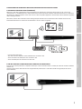
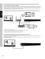
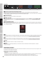
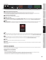
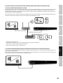
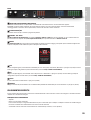
BACK
3
POWER CONNECTOR AND FUSE HOLDER
IEC power connector with fuse holder. The packaging content includes a suitable power cable.
CAUTION: Only replace the fuse with another of the same type and with the same ratings. See information on the housing. If the fuse repeatedly
blows, please contact an authorised service centre.
4
ON/OFF SWITCH
Rocker switch to turn the device on and off.
5
ETHERNET - USB - RESET
Communication expansion card with Ethernet connector, or Ethernet + Dante (64 x 64 I/O) on “D” model, for communication between the ZoneX
processor and the host computer, Micro USB recovery port for firmware recovery and IP reset button.
6
REMOTE
LD Systems remote bus for the integration with future control panels and paging microphones from LD Systems. Please note that this connector
only supports LD Systems remote bus-compatible devices and not Ethernet switch ports!
7
GPO
8 GPO outputs (logic ports) with two selectable modes per output: LED (3 mA) or sink (300 mA). 3-pole terminal blocks (pitch 3.81 mm). Please also
note the connection examples in this user manual (see GPI/O – CONNECTION EXAMPLES)
8
GPI
8 GPI inputs (logic ports), with short to ground activation. 3-pole terminal blocks (pitch 3.81 mm). Please also note the connection examples in this
user manual (see GPI/O – CONNECTION EXAMPLES)
9
OUTPUTS
8 balanced audio outputs. 3-pole terminal blocks (pitch 3.81 mm).
10
INPUTS
12 balanced audio mic/line inputs with switchable 48V phantom power per channel. 3-pole terminal blocks (pitch 3.81 mm).
CONNECTING DEVICES
LD Systems ZoneX DSP processor and other control units run on a network-based infrastructure and are configured and controlled via a computer
with the Xilica Designer software.
PREREQUISITES FOR OPERATION
• Computer
• Network interface (router, PoE switch)
A router is required for the IP address assignment and quick and easy connection to your computer and connected control units. A PoE switch is
required for control units without local power supply.
• Ethernet cable. All wired connections use a standard RJ45 Ethernet cable (Cat 5e or better).
4
6
3
7 8 9 10
5
Don‘t connect to any
ethernet switch port!
This port is only for LD
Systems remote bus
compatible devices.
DEUTSCHENGLISH
FRANÇAIS
ESPAÑOL
POLSKI
ITALIANO

7
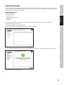
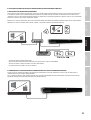
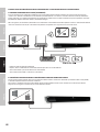
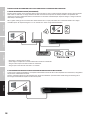
A NETWORK CONNECTION BETWEEN HOST COMPUTER AND ZONEX PROCESSOR CAN BE CREATED AS FOLLOWS:
A. ROUTER WITH ACTIVATED DHCP SERVER (RECOMMENDED)
When using a router with an enabled DHCP server, the ZoneX processor automatically acquires the IP address during start-up, as soon as the
connection exists. It is recommended to use a router and PoE switch if further control units/controllers from other manufacturers are connected to
the network. This combination provides a DHCP server and also facilitates the power supply for the connected devices. We recommend using Linksys
routers and Netgear switches.
Note: Routers/switches with activated DHCP server should generally be switched on first. And all Ethernet cables should be connected to the
hardware before the devices are switched on. This will allow for a correct IP address assignment.
• First, turn on the router/switch.
• Then connect the host computer to a DHCP enabled router via an Ethernet cable.
• Connect the router to the ZoneX processor via an Ethernet cable.
• Connect the ZoneX processor to the mains and switch it on.
B. NON-DHCP-BASED DIRECT CONNECTION OR INDIRECT CONNECTION VIA ETHERNET SWITCH
If the processor is directly connected to a computer or indirectly via a switch and no DHCP server is available, the connection cannot be established
automatically.
Therefore, non-DHCP-based connections must be configured manually. Further details can be found in the Xilica Designer help file or in the LD
Systems ZoneX FAQ.
BACK
3
POWER CONNECTOR AND FUSE HOLDER
IEC power connector with fuse holder. The packaging content includes a suitable power cable.
CAUTION: Only replace the fuse with another of the same type and with the same ratings. See information on the housing. If the fuse repeatedly
blows, please contact an authorised service centre.
4
ON/OFF SWITCH
Rocker switch to turn the device on and off.
5
ETHERNET - USB - RESET
Communication expansion card with Ethernet connector, or Ethernet + Dante (64 x 64 I/O) on “D” model, for communication between the ZoneX
processor and the host computer, Micro USB recovery port for firmware recovery and IP reset button.
6
REMOTE
LD Systems remote bus for the integration with future control panels and paging microphones from LD Systems. Please note that this connector
only supports LD Systems remote bus-compatible devices and not Ethernet switch ports!
7
GPO
8 GPO outputs (logic ports) with two selectable modes per output: LED (3 mA) or sink (300 mA). 3-pole terminal blocks (pitch 3.81 mm). Please also
note the connection examples in this user manual (see GPI/O – CONNECTION EXAMPLES)
8
GPI
8 GPI inputs (logic ports), with short to ground activation. 3-pole terminal blocks (pitch 3.81 mm). Please also note the connection examples in this
user manual (see GPI/O – CONNECTION EXAMPLES)
9
OUTPUTS
8 balanced audio outputs. 3-pole terminal blocks (pitch 3.81 mm).
10
INPUTS
12 balanced audio mic/line inputs with switchable 48V phantom power per channel. 3-pole terminal blocks (pitch 3.81 mm).
CONNECTING DEVICES
LD Systems ZoneX DSP processor and other control units run on a network-based infrastructure and are configured and controlled via a computer
with the Xilica Designer software.
PREREQUISITES FOR OPERATION
• Computer
• Network interface (router, PoE switch)
A router is required for the IP address assignment and quick and easy connection to your computer and connected control units. A PoE switch is
required for control units without local power supply.
• Ethernet cable. All wired connections use a standard RJ45 Ethernet cable (Cat 5e or better).
4
6
3
7 8 9 10
5
Don‘t connect to any
ethernet switch port!
This port is only for LD
Systems remote bus
compatible devices.
DEUTSCH ENGLISHFRANÇAISESPAÑOLPOLSKIITALIANO

8
XILICA DESIGNER SOFTWARE
The Xilica Designer software not only enables a detailed configuration of the ZoneX processor, but also offers access to the configuration of
third-party remote control units, facilitates the management of optional Dante network devices and provides universal third-party device control
integration.
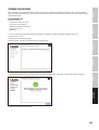
MAC OS X INSTALLATION
System requirements:
• Mac OS X 10.8 or higher
• 1 GHz processor or higher
• 500 MB free hard disk space
• 1 GB graphics card
• 4 GB RAM
1. Download the latest version of Xilica Designer software to your computer from the LD Systems website (www.ld-systems.com).
2. Open the downloaded .zip file.
3. Then open the file XilicaDesigner.mpkg.
4. An installation window now appears. Follow the individual steps.
5. If the installation process is successful, the installation window displays the message: “The installation was successful”.
7. The Xilica Designer software is now installed.
DEUTSCHENGLISH
FRANÇAIS
ESPAÑOL
POLSKI
ITALIANO

9
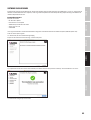
WINDOWS INSTALLATION
System requirements:
• Windows 7 or higher
• 1 GHz processor or higher
• 500 MB free hard disk space
• 1 GB graphics card
• 4 GB RAM
1. Download the latest version of Xilica Designer software to your computer from the LD Systems website (www.ld-systems.com).
2. Open the downloaded .zip file.
3. Then open the file XilicaDesigner.exe.
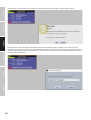
4. An installation window nor appears. Click “Install” to continue.
5. Wait until the installation process is complete. This may take a few minutes.
6. If the installation process is successful, Windows asks you for permission to allow firewall access. We recommend setting up the system so that
communication for Xilica Designer is authorized on private networks such as home or business networks. Public networks can be included if
required.
Select the desired options via the control panel and then click on “Allow Access” to complete the configuration.
7. The Xilica Designer software is now installed.
DEUTSCH ENGLISHFRANÇAISESPAÑOLPOLSKIITALIANO

10
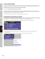
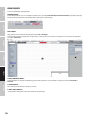
STARTING THE SOFTWARE
Find the Xilica Designer software on your desktop or in the application folder. Double-click the software to start it.
You can now create a new design project or open a design project, start the network view, or start the Dante view.
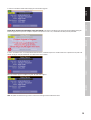
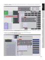
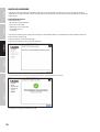
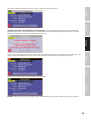
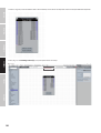
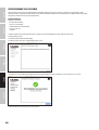
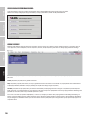
NETWORK VIEW
The network view displays all processors and control units on the network. Here you can find device information such as connection status,
computer IP address, device IP address, Mac address, device name, manufacturer and firmware version.
The connected processor(s) should be visible in network view. There is a connection status indicator in the top left corner of each device block.
Green: The device is connected and ready for operation.
Yellow: The device is connected and online but is not ready for operation. Move the cursor over the network indicator, and a pop-up window will
display a message with information about the detected problem. (The message usually says that no device design is loaded).
Red: The device is not connected and is offline. There is no communication between Xilica Designer software and the device. Please check all cables
and connections and make sure that the device is switched on. If the processor is performing a firmware upgrade or restarting, there may be a
temporary interruption.
From time to time, you may see an exclamation mark (!). This means that a firmware upgrade is available. This does not normally require
immediate intervention, but the project file does not contain updated models since the earlier firmware is not supported. Further details can be
found in the Xilica Designer help file or in the LD Systems ZoneX FAQ.
DEUTSCHENGLISH
FRANÇAIS
ESPAÑOL
POLSKI
ITALIANO

11
FIRMWARE UPGRADE
Please note that the use of an old software version with new firmware or the use of new software with old firmware works in principle but the
range of functions may be limited or the functionality may not be optimal in all cases.
We recommend always using the latest versions of software and firmware.
Before you start, check the software and firmware versions.
To check the device’s firmware version, ensure that your device is switched on and online. The network view marks devices available for a firmware
upgrade with a yellow triangle using an exclamation mark. In addition, the device’s firmware version is also listed in the device block for the
respective device.
The current software version is displayed when you click on About in the menu in the top bar.
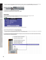
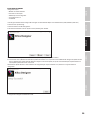
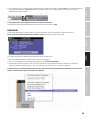
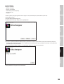
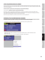
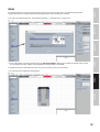
FIRMWARE UPGRADE PROCEDURE
Save the device’s design file on your computer as all programmed data will be deleted from the device during the upgrade. When the firmware
upgrade is complete, the design file can be reloaded on the device.
• The device must be online and ready for operation to perform a firmware upgrade.
• The newest firmware version for the corresponding Zone X model can be downloaded from the LD Systems website (www.ld-systems.com).
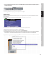
• Right-click in network view on a device block and select “Firmware Upgrade”.
DEUTSCH ENGLISHFRANÇAISESPAÑOLPOLSKIITALIANO

12
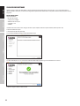
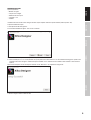
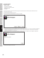
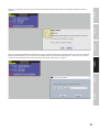
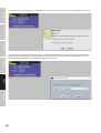
A warning then appears that the firmware upgrade will delete all data from your device. Confirm with “OK” to continue.
A dropdown menu now appears from which you can select the desired firmware file from a file system or a firmware version previously
downloaded via the “Device Firmware Manager” (in the “Device Management” menu). Confirm with “Ok” and find the folder where you saved the
new firmware file. Select the file and click “Open”.
DEUTSCHENGLISH
FRANÇAIS
ESPAÑOL
POLSKI
ITALIANO

13
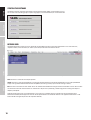
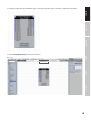
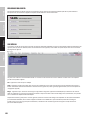
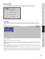
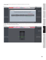
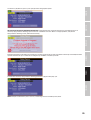
A status bar in the device window shows the progress of the firmware upgrade.
DO NOT SWITCH THE DEVICE OFF OR DISCONNECT IT FROM THE COMPUTER. If the device if switched off or disconnected from the computer during the
firmware upgrade, this may result in a complete corruption of the processor. In this case, a “USB Firmware Recovery” must be performed.
As soon as the firmware file is successfully downloaded to the device, it automatically restarts and the internal data is updated. This may take a few
minutes. During this time, the network indicator is RED and the device is offline.
When the firmware upgrade is complete, the green “ON” indication reappears.
NOTE: The yellow area with the message “No Data” means that no design has been loaded to the device.
DEUTSCH ENGLISHFRANÇAISESPAÑOLPOLSKIITALIANO

14
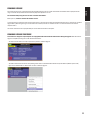
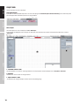
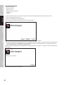
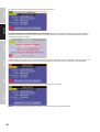
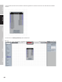
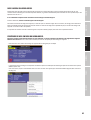
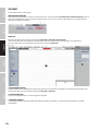
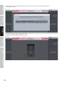
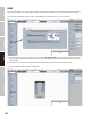
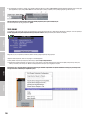
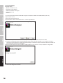
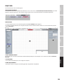
PROJECT VIEW
There are two ways to create a new project:
AUTO CONFIGURATION
If your device is listed in network view, select it and click in the top right on Create New Project from Selected Device(s). This automatically takes
you to the project view and enables you to select a design template.
EMPTY PROJECT
The second option is to create a new project via File > New Project.
If you start with an empty project, Xilica Designer asks which DSP series you want to use. ZoneX is based on the Solaro DSP series, so choose
Solaro Series.
1. “COMPONENT LIBRARY” MENU
This menu provides a list of devices and design modules for use in your project. Find the ZoneX processor in LD Systems > Processors.
2. WORK AREA
The work area is used to create and configure devices.
3. “OBJECT PROPERTY” MENU
This menu lets you configure the object features for the corresponding design.
1
2
3
DEUTSCHENGLISH
FRANÇAIS
ESPAÑOL
POLSKI
ITALIANO

15
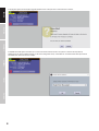
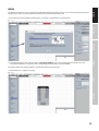
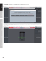
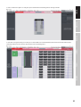
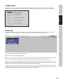
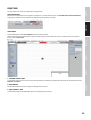
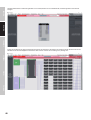
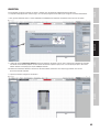
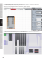
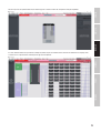
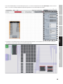
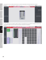
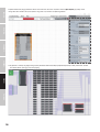
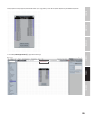
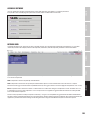
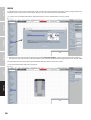
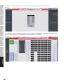
DESIGN
For demonstration purposes, in this case only one DSP hardware block will be used, however a design can also include several DSP hardware objects.
A project design can be created offline (without connected hardware) and loaded on your device later.
1. Drag and drop the desired DSP module, ZoneX1208 in this case, from the "Component Library" into the work area.
2. A selection window appears with all design templates (Select Design Template). Select one of the templates offered and you’ll see a brief
description and overview of its key features. Select a suitable template for your project, and confirm with Ok.
Detailed descriptions of the different templates can be found in the FAQ on LD Systems ZoneX.
3. The ZoneX processor is configured accordingly.
DEUTSCH ENGLISHFRANÇAISESPAÑOLPOLSKIITALIANO

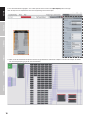
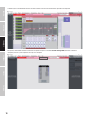
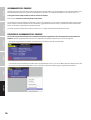
16
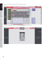
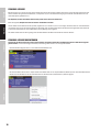
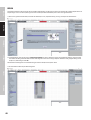
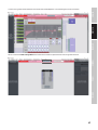
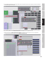
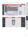
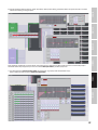
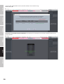
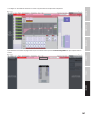
4. Select the ZoneX module to highlight it. You can now adjust the device features in the “Object Property“ menu on the right.
Note: The object features depend on the device and vary depending on the selected object.
5. Double-click on the ZoneX module to open the schematic design overview. The “Global Dante” template is selected in this example. The window
size can be changed by dragging on the corner of the window.
DEUTSCHENGLISH
FRANÇAIS
ESPAÑOL
POLSKI
ITALIANO

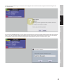
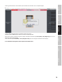
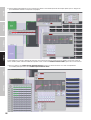
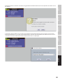
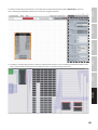
17
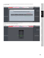
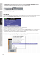
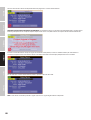
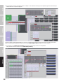
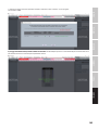
6. All DSP modules can be processed offline. Double-click on the desire module to open it. You can then adjust the settings for the DSP module to
your project’s requirements.
In this example, the phantom power has been activated and the gain values adjusted in the first two channels of the input settings. In addition, we
have renamed the first four channels in the audio input modules and processed input channel 1.
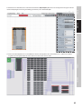
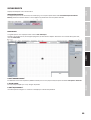
7. Now double-click on the main matrix mixer module to route the input signals to the corresponding outputs.
These can also be processed with an output processing module.
DEUTSCH ENGLISHFRANÇAISESPAÑOLPOLSKIITALIANO

18
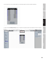
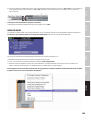
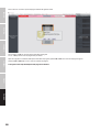
8. If you have changed the settings offline, save your project in the desired location by clicking on File > Save As. If you have changed an existing
project file, save this using File > Save. You get the same effect by clicking on the “Save” symbol in the top right of the work area.
It is a good idea to save backups of project files externally.
The file extension (naming extension) for saved project files is .pjxml.
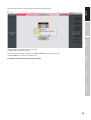
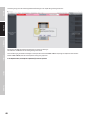
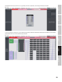
ONLINE MODE
If you select online mode, the design file is loaded on the connected device(s) and you can make changes in real time.
In this case, all devices must be connected and online (green “ON” indicator in network view).
To switch to online mode, the device module must be assigned to the physical hardware.
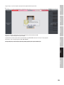
1. Select the device module you want to assign from the project view.
2. Right-click on the device module and select Map to Physical Device.
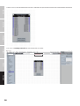
3. The recognised devices are now listed with their Mac addresses. If several identical devices are connected to the network, they can be identidied
by their Mac addresses. Network view shows the Mac addresses for the individual devices.
It is very important that the name of the device block in the design file precisely matches the unit in the network view, otherwise the design
cannot be loaded on the corresponding hardware.
DEUTSCHENGLISH
FRANÇAIS
ESPAÑOL
POLSKI
ITALIANO


20
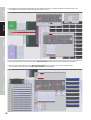
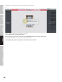
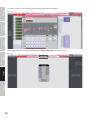
5. A window appears in which you can check the devices onto which you want to load your design.
Confirm with Ok.
Switching to online mode may take a few minutes. Do not interrupt the process! The process progress is shown in percent in a status bar at the
top of the window.
DEUTSCHENGLISH
FRANÇAIS
ESPAÑOL
POLSKI
ITALIANO
Strona jest ładowana ...
Strona jest ładowana ...
Strona jest ładowana ...
Strona jest ładowana ...
Strona jest ładowana ...
Strona jest ładowana ...
Strona jest ładowana ...
Strona jest ładowana ...
Strona jest ładowana ...
Strona jest ładowana ...
Strona jest ładowana ...
Strona jest ładowana ...
Strona jest ładowana ...
Strona jest ładowana ...
Strona jest ładowana ...
Strona jest ładowana ...
Strona jest ładowana ...
Strona jest ładowana ...
Strona jest ładowana ...
Strona jest ładowana ...
Strona jest ładowana ...
Strona jest ładowana ...
Strona jest ładowana ...
Strona jest ładowana ...
Strona jest ładowana ...
Strona jest ładowana ...
Strona jest ładowana ...
Strona jest ładowana ...
Strona jest ładowana ...
Strona jest ładowana ...
Strona jest ładowana ...
Strona jest ładowana ...
Strona jest ładowana ...
Strona jest ładowana ...
Strona jest ładowana ...
Strona jest ładowana ...
Strona jest ładowana ...
Strona jest ładowana ...
Strona jest ładowana ...
Strona jest ładowana ...
Strona jest ładowana ...
Strona jest ładowana ...
Strona jest ładowana ...
Strona jest ładowana ...
Strona jest ładowana ...
Strona jest ładowana ...
Strona jest ładowana ...
Strona jest ładowana ...
Strona jest ładowana ...
Strona jest ładowana ...
Strona jest ładowana ...
Strona jest ładowana ...
Strona jest ładowana ...
Strona jest ładowana ...
Strona jest ładowana ...
Strona jest ładowana ...
Strona jest ładowana ...
Strona jest ładowana ...
Strona jest ładowana ...
Strona jest ładowana ...
Strona jest ładowana ...
Strona jest ładowana ...
Strona jest ładowana ...
Strona jest ładowana ...
Strona jest ładowana ...
Strona jest ładowana ...
Strona jest ładowana ...
Strona jest ładowana ...
Strona jest ładowana ...
Strona jest ładowana ...
Strona jest ładowana ...
Strona jest ładowana ...
Strona jest ładowana ...
Strona jest ładowana ...
Strona jest ładowana ...
Strona jest ładowana ...
Strona jest ładowana ...
Strona jest ładowana ...
Strona jest ładowana ...
Strona jest ładowana ...
Strona jest ładowana ...
Strona jest ładowana ...
Strona jest ładowana ...
Strona jest ładowana ...
Strona jest ładowana ...
Strona jest ładowana ...
Strona jest ładowana ...
Strona jest ładowana ...
Strona jest ładowana ...
Strona jest ładowana ...
Strona jest ładowana ...
Strona jest ładowana ...
Strona jest ładowana ...
Strona jest ładowana ...
Strona jest ładowana ...
Strona jest ładowana ...
Strona jest ładowana ...
Strona jest ładowana ...
Strona jest ładowana ...
Strona jest ładowana ...
Strona jest ładowana ...
Strona jest ładowana ...
Strona jest ładowana ...
Strona jest ładowana ...
Strona jest ładowana ...
Strona jest ładowana ...
Strona jest ładowana ...
Strona jest ładowana ...
Strona jest ładowana ...
Strona jest ładowana ...
Strona jest ładowana ...
Strona jest ładowana ...
Strona jest ładowana ...
Strona jest ładowana ...
Strona jest ładowana ...
Strona jest ładowana ...
Strona jest ładowana ...
Strona jest ładowana ...
Strona jest ładowana ...
Strona jest ładowana ...
Strona jest ładowana ...
Strona jest ładowana ...
Strona jest ładowana ...
Strona jest ładowana ...
Strona jest ładowana ...
Strona jest ładowana ...
Strona jest ładowana ...
Strona jest ładowana ...
Strona jest ładowana ...
Strona jest ładowana ...
Strona jest ładowana ...
Strona jest ładowana ...
Strona jest ładowana ...
Strona jest ładowana ...
-
 1
1
-
 2
2
-
 3
3
-
 4
4
-
 5
5
-
 6
6
-
 7
7
-
 8
8
-
 9
9
-
 10
10
-
 11
11
-
 12
12
-
 13
13
-
 14
14
-
 15
15
-
 16
16
-
 17
17
-
 18
18
-
 19
19
-
 20
20
-
 21
21
-
 22
22
-
 23
23
-
 24
24
-
 25
25
-
 26
26
-
 27
27
-
 28
28
-
 29
29
-
 30
30
-
 31
31
-
 32
32
-
 33
33
-
 34
34
-
 35
35
-
 36
36
-
 37
37
-
 38
38
-
 39
39
-
 40
40
-
 41
41
-
 42
42
-
 43
43
-
 44
44
-
 45
45
-
 46
46
-
 47
47
-
 48
48
-
 49
49
-
 50
50
-
 51
51
-
 52
52
-
 53
53
-
 54
54
-
 55
55
-
 56
56
-
 57
57
-
 58
58
-
 59
59
-
 60
60
-
 61
61
-
 62
62
-
 63
63
-
 64
64
-
 65
65
-
 66
66
-
 67
67
-
 68
68
-
 69
69
-
 70
70
-
 71
71
-
 72
72
-
 73
73
-
 74
74
-
 75
75
-
 76
76
-
 77
77
-
 78
78
-
 79
79
-
 80
80
-
 81
81
-
 82
82
-
 83
83
-
 84
84
-
 85
85
-
 86
86
-
 87
87
-
 88
88
-
 89
89
-
 90
90
-
 91
91
-
 92
92
-
 93
93
-
 94
94
-
 95
95
-
 96
96
-
 97
97
-
 98
98
-
 99
99
-
 100
100
-
 101
101
-
 102
102
-
 103
103
-
 104
104
-
 105
105
-
 106
106
-
 107
107
-
 108
108
-
 109
109
-
 110
110
-
 111
111
-
 112
112
-
 113
113
-
 114
114
-
 115
115
-
 116
116
-
 117
117
-
 118
118
-
 119
119
-
 120
120
-
 121
121
-
 122
122
-
 123
123
-
 124
124
-
 125
125
-
 126
126
-
 127
127
-
 128
128
-
 129
129
-
 130
130
-
 131
131
-
 132
132
-
 133
133
-
 134
134
-
 135
135
-
 136
136
-
 137
137
-
 138
138
-
 139
139
-
 140
140
-
 141
141
-
 142
142
-
 143
143
-
 144
144
-
 145
145
-
 146
146
-
 147
147
-
 148
148
-
 149
149
-
 150
150
-
 151
151
-
 152
152
-
 153
153
-
 154
154


LD Systems Zone X1208D Hybrid Architecure DSP Matrix 12x8 Instrukcja obsługi
- Typ
- Instrukcja obsługi
- Ten podręcznik jest również odpowiedni dla
w innych językach
- español: LD Systems Zone X1208D Hybrid Architecure DSP Matrix 12x8 Manual de usuario
- italiano: LD Systems Zone X1208D Hybrid Architecure DSP Matrix 12x8 Manuale utente
- Deutsch: LD Systems Zone X1208D Hybrid Architecure DSP Matrix 12x8 Benutzerhandbuch
- français: LD Systems Zone X1208D Hybrid Architecure DSP Matrix 12x8 Manuel utilisateur
- English: LD Systems Zone X1208D Hybrid Architecure DSP Matrix 12x8 User manual