Yamaha RX-A800 Instrukcja obsługi
- Kategoria
- Amplitunery AV
- Typ
- Instrukcja obsługi

Owner’s Manual
AV Receiver English for U.S.A.

En 2
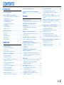
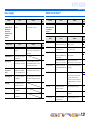
CONTENTS
INTRODUCTION
Features and capabilities ...................................................4
Using the TV OSD to operate the unit .............................5
View or modify content for the current input source
<Content window> ...........................................................5
Configuring settings for this unit
<ON SCREEN menu>......................................................5
Adjust settings for each input source
<OPTION menu> ............................................................. 6
About this manual............................................................. 7
Supplied accessories......................................................... 7
Part names and functions..................................................8
Front panel........................................................................8
Rear panel.........................................................................9
Front panel display .........................................................10
Remote control ...............................................................11
On-screen display ...........................................................12
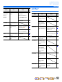
CONNECTIONS
Connecting speakers ........................................................ 13
Speaker channels and functions...................................... 13
Speaker layout ................................................................ 14
Connecting speakers and subwoofer .............................. 17
Connecting external components....................................21
Cable plugs and jacks .....................................................21
Connecting a TV monitor...............................................22
Connecting BD/DVD players and other devices............25
Connecting game consoles .............................................29
Connecting a multi-format player
or an external decoder .................................................... 29
Connecting an external amplifier ................................... 30
Connecting a SCENE link
playback-compatible device ...........................................30
Using the Trigger function to link
external component power..............................................31
Connecting audio/video recording devices.....................31
Connecting the FM/AM antennas .................................. 32
Setting up the speaker parameters automatically
(YPAO).............................................................................. 33
PLAYBACK
Basic playback procedure ............................................... 41
Adjusting high/low-frequency sound (Tone control) ..... 42
Changing input settings with a single key
(SCENE function) ............................................................ 43
Registering input sources/sound program/
HDMI OUT .................................................................... 43
Enjoying the desired sound field effect.......................... 43
Selecting sound programs and sound decoders.............. 43
Sound programs.............................................................. 47
Using the TV display to control this unit....................... 49
Basic operations via the TV screen display ................... 49
Configuring settings specific to
an individual input source (OPTION menu)................. 51
OPTION menu display and setup................................... 51
OPTION menu ............................................................... 52
Confirming and operating input sources
from the Content window ............................................... 55
Displaying the Content window on the TV screen......... 55
Switching the display between the Now Playing view
and the Content browse view ......................................... 55
FM/AM tuning ................................................................. 56
Selecting a frequency for reception (Normal tuning)..... 56
Confirming and operating the FM/AM tuner
from the Content window............................................... 58
Using HD Radio™ features............................................. 60
Selecting HD Radio™ audio programs.......................... 60
Using the iTunes Tagging............................................... 61
Displaying the HD Radio™ information ....................... 61
Confirming and operating the HD Radio™ tuner
from the Content window............................................... 62
Listening to Satellite Radio............................................. 64
Connecting the SiriusConnect™ tuner .......................... 64
Activating SIRIUS Satellite Radio™ subscription ........ 65
SIRIUS Satellite Radio™ operations............................. 65
Registering and recalling the SIRIUS Satellite Radio™
channels.......................................................................... 66
Displaying the SIRIUS Satellite Radio™ information .. 68
Confirming and operating SIRIUS Satellite Radio™
from the Content window .............................................. 69
Playing back tunes from your iPod™/iPhone™........... 71
Connecting the Universal Dock for iPod/iPhone ........... 71
Controlling an iPod™/iPhone™ .................................... 71
Playing iPod/iPhone from the menu screen
(Menu browse control)................................................... 72
Operating basic playback functions
via the remote control (Simple remote control) ............. 74
Playing iPod™/iPhone™ with wireless connection ...... 74
Playing back tunes from Bluetooth™ components ...... 76
Connecting a Yamaha Bluetooth
wireless audio receiver................................................... 76
Pairing Bluetooth™ components ................................... 76
Using Bluetooth™ components ..................................... 77

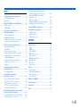
En 3
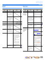
SETUP
Configuring input sources (Input menu) .......................78
Configuring input sources ..............................................78
Input menu......................................................................79
Editing the SCENE function (SCENE menu) ...............82
Editing a scene................................................................ 82
SCENE menu..................................................................83
Setting sound program parameters
(Sound Program menu) ...................................................85
Editing sound programs..................................................85
CINEMA DSP parameters ............................................. 86
Parameters usable in certain sound programs ................88
Parameters usable in surround decoder .......................... 89
Setting various functions (Setup menu) .........................90
Operating the Setup menu ..............................................90
Setup menu .....................................................................91
Manages settings for speakers ........................................91
Setting the audio output function of this unit .................95
Setting this unit’s video output function.........................96
Setting HDMI functions .................................................97
Setting this unit’s multi-zone function ......................... 100
Making the receiver easier to use ................................. 100
Language ......................................................................103
Confirming information of this unit
(Information menu) .......................................................104
Selecting information ...................................................104
Controlling other components
with the remote control.................................................. 105
Keys connecting external components .........................105
Default remote control code settings............................106
Registering remote control codes
for external component operations ............................... 106
Resetting all remote control codes ............................... 107
Extended functionality that can be configured
as needed (Advanced Setup menu)...............................108
Displaying/Setting the Advanced Setup menu .............108
Setting the impedance of speakers ..............................108
Avoiding crossing remote control signals
when using multiple Yamaha receivers ........................ 109
Resetting the SIRIUS Satellite Radio™
parental lock code......................................................... 109
Changing TV format .................................................... 110
Removing HDMI video output up-scaling limits......... 110
Initializing various settings for this unit....................... 110
Using the HDMI Control function ............................... 111
Using multi-zone configuration .................................... 115
Connecting Zone2 ........................................................ 115
Controlling Zone2 ........................................................ 116
Using the party mode ................................................... 116
APPENDIX
Troubleshooting ............................................................. 117
General ......................................................................... 117
HDMI™ ....................................................................... 119
Tuner (FM/AM) ........................................................... 120
HD Radio™ Reception ................................................ 120
iTunes Tagging ............................................................. 121
SIRIUS Satellite Radio™............................................. 121
iPod™/iPhone™ .......................................................... 122
Bluetooth™ .................................................................. 123
Remote control ............................................................. 123
Glossary .......................................................................... 124
Audio information ........................................................ 124
Sound program information ......................................... 125
Video information ........................................................ 125
Video conversion .......................................................... 126
Information on HDMI™............................................... 127
About trademarks.......................................................... 127
Specifications.................................................................. 128
Index ............................................................................... 130

En 4
INTRODUCTION
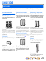
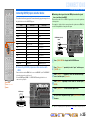
■ Built-in high-quality, high-power 7-channel amplifier
■ 6 HDMI input jacks (5 + 1 VIDEO AUX) supporting Audio Return Channel and 3D
video signal
■ 2 HDMI output jacks
– Selecting the HDMI OUT jack ................................................................................................................41
■ 1-button input/sound program switching (SCENE function)................................43
■ Speaker connections for 2- to 7.1-channel configurations
– Speaker impedance configuration............................................................................................................18
– Speaker channels and functions ...............................................................................................................13
– Speaker layout..........................................................................................................................................14
– Speaker cable connection.........................................................................................................................17
– Subwoofer cable connection ....................................................................................................................20
– High quality playback using bi-amplification connections .....................................................................18
■ Automatic settings for speaker acoustic parameters
(YPAO - Yamaha Parametric Room Acoustic Optimizer) ......................................33
■ External component connection (max. 16 inputs) and playback
– External component connection...............................................................................................................21
– Protective cover for front panel jacks ........................................................................................................7
– Configuring the settings specific for each input source <OPTION menu>.............................................51
– Playback from external components........................................................................................................41
– Playback from an iPod/iPhone with wired connection............................................................................72
– Playback from an iPod/iPhone with wireless connection........................................................................74
– Playback from a Bluetooth component (Bluetooth and components sold separately) ............................76
■ FM/AM tuner
– HD Radio digital broadcast listening.......................................................................................................60
– Receiving an FM/AM broadcast..............................................................................................................56
– Presetting stations ....................................................................................................................................56
– Simple preset tuning ................................................................................................................................56
– Changing Audio mode (Auto/Mono).......................................................................................................58
■ SIRIUS Satellite Radio™
– Receiving a channel .................................................................................................................................65
– Presetting channels ..................................................................................................................................66
– Displaying information ............................................................................................................................68
■ Multi-channel, multi-format playback
– Sound field effect selection......................................................................................................................43
– Playback without sound field effects .......................................................................................................44
– Stereo playback........................................................................................................................................44
– Compressed-music playback ...................................................................................................................46
■ Front panel information display/on-screen display (OSD) on the TV screen
– Switching information on the front panel display ...................................................................................10
– Operating this unit using the on-screen display.......................................................................................12
■ Volume adjustment functions
– Easy listening at low volumes < Adaptive DRC> ...................................................................................53
– Adjusting volume between input sources <Volume Trim> .....................................................................54
■ Remote control operation
– External component operation with this unit’s remote control..............................................................105
■ Playing back the audio source in another room
– Using the internal amplifier for playback ................................................................................................18
– Using the external amplifier for playback .............................................................................................115
– Configuring the settings for another room.............................................................................................115
– Controlling the external component in another room............................................................................116
■ Other features
– Standby mode after a specific amount of time <Sleep timer>.................................................................11
– Charging the iPod/iPhone when this unit is in standby mode <iPod Standby Charge> ..........................80
– Tagging songs for subsequent preview and purchase on iTunes <iTunes Tagging> ...............................61
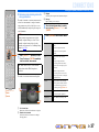
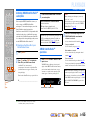
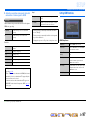
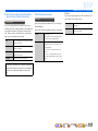
Features and capabilities
Most of this unit’s functions can be operated by following instructions displayed on the TV screen.
Refer to “Using the TV OSD to operate the unit” on the following pages for information on
functions that can be controlled using the on-screen display.

INTRODUCTION
En 5
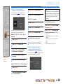
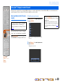
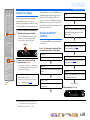
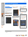
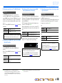
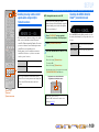
This unit features a sophisticated on-screen display (OSD) for the TV screen. The OSD is designed to enable visual guidance that simplifies operations. The OSD mainly displays the ON SCREEN and
OPTION menus, as well as the Content window that displays the content of current input sources.
■ Select an input source, SCENE and sound program
– Select an input source ..............................................................................................................................49
– Select a SCENE .......................................................................................................................................50
– Select a sound program............................................................................................................................50
View or modify content for the current input source <Content
window>
■ Operate the AM/FM tuner or SIRIUS Satellite Radio
– Display a list of preset stations/channels for selection ......................................................................59, 70
– Display information on the station/channel currently received .........................................................58, 69
– Perform operations such as searching for and registering stations/channels using the Utility
<Utility>.............................................................................................................................................58, 69
■ Display the list of iPod music sources
– Display the list of iPod music sources for selection ................................................................................72
– Perform operations such as play, stop and pause using the TV screen <Menu browse control> ............72
– Perform basic playback functions such as play, stop and pause
via the remote control <Simple remote control> .....................................................................................74
Configuring settings for this unit <ON SCREEN menu>
– Display the ON SCREEN menu on the TV screen..................................................................................49
■ Select and configure an input source
– Select an input source ..............................................................................................................................49
– Play the audio/video signal from the selected input source.....................................................................41
– Change the input source name <Rename/Icon Select> ...........................................................................79
– Select the audio input jack separately from the video input jack <Audio In>.........................................80
– Specify a format for digital audio signals <Decoder Mode>...................................................................80
– Enhance the sound of compressed audio <Enhancer>.............................................................................80
– Output a video signal input from another input source
while playing a multi-channel audio signal <Video Out> .......................................................................81
– Charge the iPod/iPhone when this unit is in standby mode <Standby Charge>......................................80
■ Select and customize a SCENE
– Select a SCENE .......................................................................................................................................50
– Register or clear settings for a selected SCENE <Save>, <Reset> .........................................................83
– Turn on a Yamaha BD/DVD player or CD player connected to this unit automatically
when a SCENE is selected <SCENE IR>................................................................................................83
■ Select and adjust a sound program (sound program)
– Select a sound program............................................................................................................................50
– Adjust sound program parameters ...........................................................................................................85
■ Display settings information for this unit
– Display audio signal information <Audio Signal>................................................................................104
– Display video signal information <Video Signal> ................................................................................104
– Display HDMI signal information <HDMI - Monitor Info.>................................................................104
■ Adjust acoustic parameters to match your speakers and listening environment
– Specify speaker acoustic parameters automatically
(Yamaha Parametric Room Acoustic Optimizer - YPAO).......................................................................33
– Set up this unit’s speaker configuration simply <Power Amp Assign> ..................................................91
– Specify settings for each speaker <Configuration>.................................................................................92
– Control volume control for each speaker <Level> ..................................................................................93
– Apply speaker distance settings <Distance> ...........................................................................................93
– Control equalizer sound quality <Parametric EQ>..................................................................................94
– Adjust test tone speaker <Test Tone> ......................................................................................................94
■ Adjust audio signals output from this unit
– Correct lag between audio and video signals <Lipsync> ........................................................................95
– Select a dynamic range adjustment method <Dynamic Range> .............................................................95
– Specify the maximum volume <Max Volume>.......................................................................................95
– Specify the initial volume <Initial Volume>............................................................................................96
– Adjust DSP effect and volume level <Adaptive DSP Level>..................................................................96
Using the TV OSD to operate the unit
Continues to the
next page

INTRODUCTION
Using the TV OSD to operate the unit
En 6
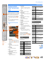
■ Adjust video signals output from this unit
– Convert analog video signal to another type of signal <Analog to Analog Conversion> .......................96
– Specify the resolution and aspect ratio of analog video signal converted to HDMI or specify
upscaling resolution for 480i/576i- or 480p/576p-HDMI output signal <Processing>...........................97
■ HDMI settings
– Assign the audio input source for the TV <TV Audio Input>.................................................................98
– Listen to TV audio with HDMI cable connection <ARC (Audio Return Channel)>..............................98
– Transmit HDMI audio/video to the TV during standby mode <Standby Through> ...............................99
– Change the output destination of HDMI input audio signals <Audio Output>.......................................99
■ Enable listening in multiple rooms (multi-zone function)
– Adjust Zone2 volume <Zone2 Set>.......................................................................................................100
■ Specify other functions for this unit
– Enter standby mode automatically when no operations are performed <Auto Power Down>..............101
– Adjust the brightness of the front panel display <Dimmer> .................................................................101
– Change the wall paper displayed on the TV screen <Wall Paper>........................................................101
– Specify the function of the TRIGGER OUT jack for controlling external components
<Trigger Output> ...................................................................................................................................102
– Prohibit changes to settings <Memory Guard> .....................................................................................103
■ Select a language
– Change the language displayed on the TV screen <Language>............................................................103
Adjust settings for each input source <OPTION menu>
– Display the OPTION menu on the TV screen .........................................................................................51
– Select the 5.1-channel signal playback method <Extended Surround>...................................................53
– Adjust bass and treble levels <Tone Control> .........................................................................................52
– Enable low-volume background music <Adaptive DRC>.......................................................................53
– Adjust the volume of input sources <Volume Trim>...............................................................................54
– Adjust the vertical position of dialogues <Dialogue Lift> ......................................................................53

En 7
INTRODUCTION
Using the TV OSD to operate the unit
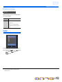
About this manual
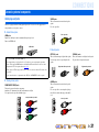
Supplied accessories
Check that you received all of the following parts.
• Remote control
• Batteries (AAA, R03, UM-4) x 2
• YPAO microphone
• AM loop antenna
• Indoor FM antenna
• VIDEO AUX input cover
• Some features are not available in certain regions.
• This manual is created prior to production. Design and
specifications are subject to change in part as a result of
improvements, etc. In case of differences between the manual and
product, the product has priority.
• “
dHDMI1” (example) indicates the name of the parts on the
remote control. Refer to the “Remote control” (☞
p. 11) for the
information about each position of the parts.
• J
1 indicates that the reference is in the footnote. Refer to the
corresponding numbers on the bottom of the page.
• ☞
indicates the page describing the related information.
• Click on the “ ” at the bottom of the page to display the
corresponding page in “Part names and functions.”
Front panel
Rear panel
Front panel display
Remote control
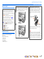
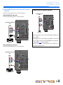
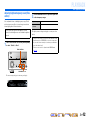
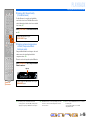
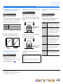
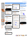
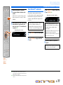
■ Attaching the VIDEO AUX input cover (supplied)
To protect against dust, attach the supplied VIDEO AUX input
cover to the VIDEO AUX jacks when you do not use the jacks.
To remove the cover, push the left section of it.
Attach the cover
PUSH
Remove the cover
■ Installing batteries in the remote control
When inserting batteries in the remote control, remove the
battery compartment cover from the reverse side of the remote
control, and insert two AAA batteries into the battery
compartment so that they match with the polarity markings (+
and -).
Replace the batteries with new ones if the remote control can
only be operated within a narrow range.
NOTE
If there are remote control codes for external components
registered to the remote control, removing the batteries for more
than 2 minutes, or leaving exhausted batteries in the remote
control, may clear the remote control codes. If this should occur,
replace the batteries with new ones, and set the remote control
codes.
a
c
b
Battery compartment
cover
Battery compartment

INTRODUCTION
En 8
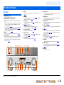
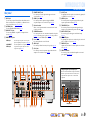
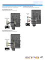
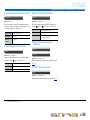
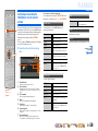
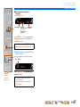
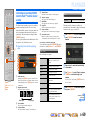
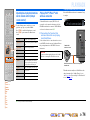
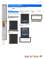
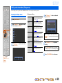
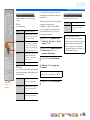
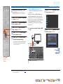
Front panel
a MAIN ZONE A (Power)
Switches this unit between on and standby mode.
b HDMI Through/iPod Charge indicator
Lights up in any of the following cases while the unit is in standby
mode.
• When the Standby Through function is enabled and audio/video from
an external component connected with HDMI is output to a TV
during standby mode (☞
p. 99).
• When an iPod/iPhone, which is placed in the Universal Dock for iPod/
iPhone, is charging while the unit is in standby mode (☞
p. 74).
This indicator also lights up when the Yamaha iPod wireless receiver
is connected to this unit (☞
p. 74).
c ZONE2
Switches to enable/disable the audio output to Zone2 (☞
p. 116).
d ZONE CONTROL
Switches to Zone2 operation mode. This unit, or its remote control,
can be used to select input sources or adjust volume for an external
amplifier in another room or the built-in amplifier for speakers in
another room (☞
p. 116).
e INFO
Changes the information displayed on the front panel display
(☞
p. 10).
f MEMORY
Registers FM/AM stations as preset stations (☞
p. 56) or SIRIUS
channels as preset channels (☞
p. 66). J1
g PRESET j / i
Selects an FM/AM preset station (☞
p. 58) or a SIRIUS preset channel
(☞
p. 67). J1
h FM/AM (CATEGORY l / h)
Sets the FM/AM tuner band to FM or AM (☞
p. 56). J1
Selects a channel category for a SIRIUS (☞
p. 66).
i Front panel display
Displays information on this unit (☞
p. 10).
j TUNING/CH jj / ii
Changes FM/AM tuner frequencies (☞
p. 56) or SIRIUS Satellite
Radio channels (☞
p. 66). J1
k PURE DIRECT
Switches this unit to Pure Direct mode (☞
p. 46).
l INPUT selector
Selects an input source from which to playback. Rotate this selector to
cycle through the input sources in order.
m PHONES jack
For plugging headphones in. Sound effects applied during playback
can also be heard through the headphones.
n YPAO MIC jack
Connect the supplied YPAO microphone and adjust the speaker balance
automatically (☞
p. 33).
o TONE CONTROL
Adjusts high-frequency/low-frequency output of speakers/headphones
(☞
p. 42).
p SCENE
Switches the input source, the sound program, and the HDMI OUT
with a single button (☞
p. 43, p. 82). When this unit is in standby
mode, press this key to switch on.
q PROGRAM selector
Selects a sound program (☞
p. 43). Rotate this selector to cycle
through sound programs.
r STRAIGHT
Changes a sound program to straight decoding mode (☞
p. 44).
s VIDEO AUX jacks
For connecting game consoles to this unit temporarily (☞
p. 29).
Attach the supplied VIDEO AUX input cover when not using this jack
(☞
p. 7).
t VOLUME
Adjusts the volume level.
Part names and functions
VIDEO
AUX
PHONES
YPAO MIC
SILENT
CINEMA
TONE
CONTROL
STRAIGHT
VOLU ME
TV
BD
DVD
CD
RADIO
INPUT
PROGRAM
SCENE
VIDEO
AUDI O
HDMI IN
L
R
INFO
ZONE
CONTROL
ZONE2
MAIN ZONE
MEMORY
PRESET
FM AM
CATEGORY
TUNING/CH
PURE DIRECT
rm n q
a
olts
ic f g ked h jb
p
JJ
1 : Usable when you have selected TUNER or SIRIUS input.

En 9
INTRODUCTION
Part names and functions
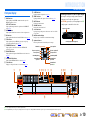
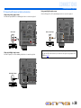
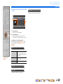
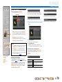
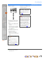
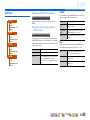
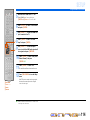
Rear panel
a DOCK jack
For connecting an optional Universal Dock for iPod/iPhone (such as
YDS-12), iPod wireless receiver (YID-W10), or Bluetooth wireless
audio receiver (YBA-10) (☞
p. 71, p. 74, p. 76).
b ANTENNA jacks
For connecting AM and FM antennas (☞
p. 32).
c HDMI OUT 1-2 jacks
For connecting an HDMI - compatible TV to output audio/video
signals (☞
p. 23).
d MONITOR OUT jacks
e REMOTE IN/OUT jacks
For connecting an external component that supports the remote
control function (☞
p. 30).
f HDMI1-5 jacks
For connecting external components equipped with HDMI-
compatible outputs to receive audio/video signals (☞
p. 25).
g RS-232C terminal
This is a control expansion terminal for custom installation. Consult
your dealer for details.
h SPEAKERS terminals
For connecting the front, center, surround and surround back speakers
(☞
p. 17). Connect the presence speakers (☞p. 17) or the speakers for
Zone2 (☞
p. 18) to the EXTRA SP jacks.
i Power cable
For connecting this unit to an AC wall outlet.
j SIRIUS jack
For connecting a SiriusConnect tuner (sold separately) (☞
p. 64).
k AV1-6 jacks
For connecting to external components equipped with audio/video
outputs to receive audio/video signals (☞
p. 26).
l AV OUT jacks
For outputting audio/video signals received when analog inputs (AV3-
6 or AUDIO1-2) are selected (☞
p. 31).
m AUDIO1-2 jacks
For connecting external components equipped with analog audio
outputs to input sound into this unit (☞
p. 28).
n TRIGGER OUT jack
For connecting an external component that supports the trigger
function to operate it linked with operation of this unit (☞
p. 31).
o MULTI CH INPUT jacks
For connecting a player that supports a multi-channel output
(☞
p. 29).
p AUDIO OUT jacks
For outputting audio signals received when analog jacks, such as the
AV5-6 or AUDIO1-2 are selected (☞
p. 31).
q ZONE2 OUT jacks
Outputs sound of this unit to an external amplifier set in a different
room. (☞
p. 115).
r PRE OUT terminals
For connecting a subwoofer with built-in amplifier or an external
power amplifier (☞
p. 20, p. 30).
VIDEO jack For connecting a TV capable of receiving video
input, and outputting video signals to it (☞p. 23).
COMPONENT
VIDEO jacks
For connecting TV that are compatible with
component video signals, using three cables to
output video signal (☞p. 23).
AV
OUT
AUDIO
OUT
ZONE2
OUT
SURROUND
SUR.BACK
PRE OUT
SUBWOOFER
1
2
FRONT
CENTERSINGLE
HDMI OUT
12
ARC ARC
SELECTABLE
COMPONENT
VIDEO
VIDEO
P
R
P
B
Y
(
TV
)
AV 4
AV 5
AV 6
AUD
IO 1
AUD
IO 2
MULTI CH INPUT
O
PTI
C
AL
HDMI 1
(
BD
/
DV
D
)
HDMI 2
HDMI
3
HDMI 4 HDMI 5
C
ENTER
SU
RR
OU
N
D
SU
RR
OU
ND BA
C
K
/
BI
-
AMP
S
INGL
E
F
R
O
N
T
SUBWOOFE
R
SU
R.BA
CK
SU
RR
OU
ND
TRIGGER OUT
+12V
0
.1
A
MAX.
FR
O
NT
CENTE
R
IN
REMOTE
O
U
T
S
PEAK
E
SPEAKE
NTENNA
FM
o
GN
D
AM
7
5
RS
-2
3
2
C
Distinguishing the input and output jacks
The area around the audio/video output jacks is marked
in white to prevent connection errors. Use these jacks to
output audio/video signals to a TV or other external
component.
Output jacks
DOCK
(
TV
)
AV 3
AV 4
AV 5
AV 6
AUDI O 1
AUDI O 2
MULTI CH INPUT
(
CD
)
COAXIAL
OPTICAL
VIDEO
HDMI 1
(
BD/DVD
)
HDMI 2 HDMI 3
HDMI 4 HDMI 5
CENTER
SURROUND
SURROUND BACK/
BI-AMP
SINGLE
EXTRA SP
FRONT
AV
OUT
SUBWOOFER
AUDIO
OUT
ZONE2
OUT
SUR.BACK
SURROUND
SURROUND
SUR.BACK
PRE OUT
SUBWOOFER
1
2
FRONT
TRIGGER OUT
+12V
0.1A MAX.
FRONT
CENTER
IN
REMOTE
OUT
CENTERSINGLE
HDMI OUT
12
ARC ARC
SELECTABLE
SPEAKERSSPEAKERS
ANTENNA
FM
HD Radio
GND
AM
75
OPTICAL
AV 1
AV 2
COAXIAL
COMPONENT
VIDEO
P
R
P
B
Y
SIRIUS
RS-232C
COMPONENT
VIDEO
VIDEO
MONITOR OUT
P
R
P
B
Y
ZONE2/PRESENCE
adcfg ihe
pqjklmo r
b
n

En 10
INTRODUCTION
Part names and functions
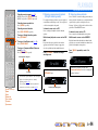
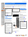
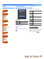
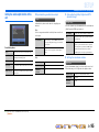
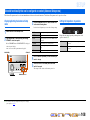
Front panel display
a HDMI indicator
Lights up during normal HDMI communication when any of the
HDMI1-5 inputs are selected.
OUT 1/OUT 2 indicators
Lights up which outputs audio/video signals from the HDMI OUT
jack (☞
p. 23).
b SIRIUS indicator
Lights up when a SiriusConnect tuner is selected as an input source.
c HD indicator
Lights up when this unit is tuned into the HD Radio station (☞
p. 60).
d TAG indicator
Lights up when the selected HD Radio program (or song being
played) supports iTunes Tagging (☞
p. 61).
e CINEMA DSP indicator
Lights up when a sound field effect that uses CINEMA DSP
technology is selected.
f ENHANCER indicator
Lights up when the Compressed Music Enhancer mode is turned on
(☞
p. 46).
g CINEMA DSP 3D indicator
Lights up when CINEMA DSP 3D is activated (☞
p. 45).
h Tuner indicator
Light up according to the status of a received station (☞
p. 56).
i SLEEP indicator
Lights up when the sleep timer is on (☞
p. 11).
j ZONE2 indicator
Lights up when the audio output to Zone2 is enabled (☞
p. 116).
k MUTE indicator
Flashes when audio is muted.
l VOLUME indicator
Displays the current volume level.
m Cursor indicators
Light up if corresponding cursors on the remote control are available
for operations.
n Multi information display
Displays a range of information on menu items and settings.
o Speaker indicators
Indicate speaker terminals from which signals are output.
SW
C
LR
SL SR
SBL SBRSB
PR
PL
Front speaker L
Surround speaker L
Subwoofer
Front speaker R
Surround speaker R
Center speaker
Surround back
speaker L
Surround back
speaker R
Surround back
speaker J1
Presence speaker L
Presence speaker
R
■ Switching information on the front panel display
The front panel can display sound programs and surround
decoder names as well as the active input source.
Press INFO Key repeatedly to cycle through input source J2
→ sound program → surround decoder in order.
SWSW
C
LR
SL SR
SBL SBR
STRAIGHT
HDMI1
VOL.
Input source name
Sound program (DSP program)
STEREO
SLEEP
VOL.
TUNED
SW
C
LR
SL SR
MUTE
ENHANCER
OUT 1 OUT 2
3
ZONE
2
SBL SBRSB
PR
PL
TAG
HD
SIRIUS
mn om
aefc dgbhilkj
J
1 : “SB” is displayed when using a 6.1-channel configuration only.
J
2 : During FM/AM reception, the frequency is displayed instead of the input source. During SIRIUS Satellite Radio signals reception, the channel is displayed instead of the input source.

En 11
INTRODUCTION
Part names and functions
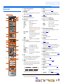
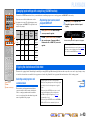
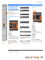
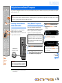
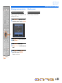
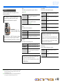
Remote control
a Remote control signal transmitter
Transmits infrared signals.
b MAIN/ZONE2
Switches the zone to be operated by the remote control between the
Main zone and Zone2 (☞
p. 116).
c SOURCE A (SOURCE Power)
Switches an external component on and off.
d Input selector
Select an input source on this unit from which to playback.
e Radio control keys
Operates the FM/AM tuner. These keys are used when using the tuner
input.
f INFO
Cycles the information displayed on the front panel display (the name
of the currently selected input source, the sound program, the
surround decoder, the FM/AM tuner frequency, etc.).
g SLEEP
Switches this unit to standby mode automatically after a specified
period of time has elapsed (sleep timer). Press this key repeatedly to
set the time for the sleep timer function.
The SLEEP indicator lights up when the sleep timer is on.
h PARTY
Switches the party mode on and off (☞
p. 116).
i SCENE
Switch the input source and the sound program with a single button
(☞
p. 43). When this unit is in standby mode, press this key to switch on.
j ON SCREEN
Turns on and off the ON SCREEN menu.
k Cursor B / C / D / E, ENTER, RETURN
l External component operation keys
Operate recording, playback, and menu displays etc. for external
components (☞
p. 105). J1
m Numeric keys
Enter numbers.
n TV control keys
Operate a monitor such as a TV.
o CODE SET
Sets remote control codes for external component operations
(☞
p. 106).
p SOURCE/RECEIVER
Switches remote control key function to operate this unit or an
external component (☞
p. 105). Operate an external component when
this key glows green, or this unit when this key glows orange.
q RECEIVER A (RECEIVER Power)
Switches this unit between on and standby mode.
r HDMI OUT
Switches the output jack connected to an HDMI compatible TV (☞
p. 41).
s Sound selection keys
Switch between the sound field effect (sound program) you are using
and the surround decoder (☞
p. 43).
t OPTION
Turns on and off the OPTION menu (☞
p. 51).
u VOLUME +/-
Adjust the volume level (☞
p. 41).
v MUTE
Turns the mute function of the sound output on and off (☞
p. 41).
w HD Radio keys
SCENE
RETURN
VOLUME
ENHANCER
SUR. DECODE
STRAIGHTSLEEP PURE DIRECT
HDMI
AV
AUDIO
1234
125
V-AU X
FM
INFO
MEMORY
AM
PRESET
PART Y
MOVIE MUSIC
BD
DVD
TV
CD
RADIO
MUTE
ENTER
7856
90
10
1234
REC
ENT
TV
TV VOL TV CH
TOP
MENU
POP-UP
MENU
DISPLAY
SOURCE
MAIN
ZONE 2
RECEIVER
CODE SET
INPUT
MUTE
DOCK
HDMI OUT
MULTI
OPTION
ON SCREEN
5
1234
6
[ A ]
SIRIUSTUNER
TUN./CH
CATEGORY
TAGHOLD
PRG SELECT
a
c
b
e
i
j
t
u
v
m
n
k
f
l
g
h
p
q
r
o
d
s
w
HDMI1-5 HDMI1-5 jacks
V-AUX Front panel VIDEO AUX jacks
AUDIO1-2 AUDIO1-2 jacks
AV1-6 AV1-6 jacks
[A] Changes the external component to operate with
the lExternal component operation keys
without changing inputs. J1
MULTI CH INPUT MULTI CH INPUT jacks
DOCK A Universal Dock for iPod/iPhone, iPod wireless
receiver, or Bluetooth wireless audio receiver
connected to the DOCK jack.
TUNER FM/AM tuner
SIRIUS A SIRIUS tuner connected to the SIRIUS jack.
FM Sets the FM/AM tuner band to FM.
AM
(CATEGORY D / E)
Sets the FM/AM tuner band to AM.
Selects a channel category for a SIRIUS.
MEMORY Presets radio stations.
PRESET F / G Selects a preset station.
TUN./CH H / I Changes tuning frequencies or SIRIUS Satellite
Radio channels.
Sleep 120min. Sleep 90min.
Sleep 60min.Sleep 30min.Sleep Off
Cursor B / C / D / E Select menu items and change settings when
menus, etc, are displayed.
ENTER Confirms a selected item.
RETURN Returns to the previous screen when menus are
displayed, or close the menu.
TAG Stores “tag” data to the iPod or internal memory
of this unit (☞p. 61).
PRG SELECT Selects an HD Radio audio program (☞p. 60).
J
1 : You can use lExternal component operation keys for each input source to operate registered components. Remote control codes must be registered for each input
in advance if you want to operate external components (☞
p. 106).

INTRODUCTION
Part names and functions
En 12
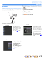
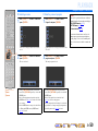
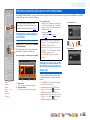
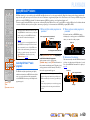
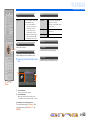
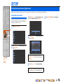
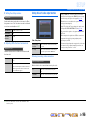
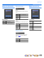
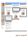
On-screen display
When a TV is connected to this unit, the supplied remote control can be used to specify and verify this
unit’s settings via menus and options displayed on the TV screen.
The following displays are available in the on-screen display.
■ Displaying the following menus or viewing the current status of this unit on the
TV screen
• ON SCREEN menu
Press ON SCREEN to display the ON SCREEN menu.
• OPTION menu
Press OPTION to display the OPTION menu.
• Content window
Press Input selector to display the Content window.
ON SCREEN menu
Detailed settings for this unit can be
configured. Use this menu to select desired
settings, change their values, or check the
current status of this unit.
Refer to “SETUP” (☞
p. 78) for details.
OPTION menu
Configure the optional settings for each input
source. Settings such as “Tone Control” and
“Volume Trim” are applied to this unit
regardless of the input source.
Refer to “Configuring settings specific to an
individual input source (OPTION menu)”
(☞
p. 51) for details.
Content window
Includes the Content browse view and the
Now Playing view. The Now Playing view
displays the status of the source from which
music is currently played back. Adjust settings
for music content from the Content browse
view.
Refer to “Confirming and operating input
sources from the Content window” (☞
p. 55)
for details.

En 13
CONNECTIONS
This unit uses acoustic field effects and sound decoders to bring you the impact of a real movie theater or concert hall. These effects will be brought to you with ideal speaker positioning and
connections in your listening environment.
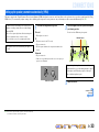
Speaker channels and functions
■
Front left and right speakers
The front speakers are used for the front channel sounds (stereo
sound) and effect sounds.
Front speaker layout:
Place these speakers at an equal distance from the ideal listening
position in the front of the room. When using a projector screen,
the appropriate top positions of the speakers are about 1/4 of the
screen from the bottom.
■
Center speaker
The center speaker is for the center channel sounds (dialog, vocals,
etc.).
Center speaker layout:
Place it halfway between the left and right front speakers. When
using a TV, place the speaker just above or just under the center of
the TV with the front surfaces of the TV and the speaker aligned.
When using a screen, place it just under the center of the screen.
■
Surround left and right speakers
The surround speakers are for effect and vocal sounds with the 5.1-
channel speakers providing rear-area sounds. When used with 6.1/
7.1-channel (including surround back channel), sound for right and
left rear-area is output.
Surround speaker layout:
Place the speakers at the rear of the room on the left and right sides
facing the listening position. They should be placed between 60
degrees and 80 degrees from the listening position and with the
speaker tops at a height of 4.9 – 5.9 ft. (1.5 – 1.8 m) from the floor.
■
Presence left and right speakers
The presence speakers are used for front effect sounds. When used
in combination with the sound programs (☞
p. 43), a sound with a
richer and more spatial presence is possible.
Presence speaker layout:
Place the left and right presence speakers 1.6 – 3.3 ft. (0.5 – 1 m) to
the outside of the left and right front speakers respectively. The
tops of the presence speakers should be 5.9 ft. (1.8 m) above the
floor.
■
Surround back left and right speakers
Outputs the rear effect. When used with 6.1ch sound, sound from
the left and right sound surround back speakers is mixed and output
from a single speaker. When used with 5.1ch sound, sound from
surround back speakers is distributed between the left and right
surround speakers.
Surround back speaker layout:
When used with 7.1ch sound, arrange the left and right speakers
towards the listening position, to the rear of the listening position.
Arrange the left and right speakers at least 1 ft. (30 cm) apart. The
same separation as with the front left and right speakers is
optimum.
When used with 6.1ch sound, arrange these to the rear of the
listening position.
■
Subwoofer
The subwoofer speaker is used for bass sounds and low-frequency
effect (LFE) sounds included in Dolby Digital and DTS. Use a
subwoofer that is equipped with built-in amplifier.
Subwoofer speaker layout:
Place it to the outside of the front left and right speakers facing
slightly inward to reduce echoes from the wall.
Connecting speakers
Ex.
Ex.
Ex.
Ex.
Ex.
Ex.

CONNECTIONS
Connecting speakers
En 14
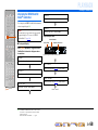
Speaker layout
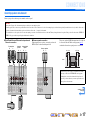
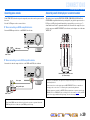
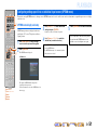
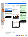
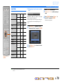
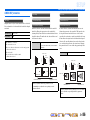
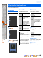
■
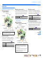
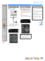
Enjoying the 7.1 channel audio source
■ 7.1-channel speaker layout
(7 speakers + subwoofer)
■ Connections of speakers
Connect the speakers to the following jacks according to the
speaker layout. Refer to “Front/Center/Surround/Surround back
speaker and Subwoofer connection” and “Presence speaker
connection” for details on connecting speakers (☞
p. 17).
■ Assigning a speaker configuration
A speaker configuration must be assigned to this unit to activate the
speakers. Use the “Power Amp Assign” function to easily apply the
appropriate speaker settings to this unit according to the speaker
configuration. Speakers for this layout can be activated at the
default “Power Amp Assign” setting (☞
p. 91).
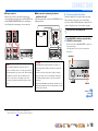
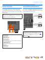
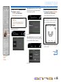
■
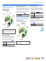
Adding the presence speakers for a richer
sound field effect
■ Presence speaker layout
(7 speakers + subwoofer + presence speakers)
■ Connections of speakers
Connect the speakers to the following jacks according to the
speaker layout. Refer to “Front/Center/Surround/Surround back
speaker and Subwoofer connection” and “Presence speaker
connection” for details on connecting speakers (☞
p. 17).
■ Assigning a speaker configuration
A speaker configuration must be assigned to this unit to activate the
speakers. Use the “Power Amp Assign” function to easily apply the
appropriate speaker settings to this unit according to the speaker
configuration. Speakers for this layout can be activated at the
default “Power Amp Assign” setting (☞
p. 91).
Audio from a 7.1-channel audio source can be played back with
no degradation with this speaker configuration.
Speaker jacks FRONT L/R, CENTER, SURROUND L/R,
SURROUND BACK L/R, SUBWOOFER
EXTRA SP jack No used
Front speaker L
Front speaker R
Subwoofer
Center speaker
Surround speaker L
Surround
speaker R
Surround back speaker RSurround back speaker L
12 in (30 cm)
or more
Power Amp Assign 7ch Normal (Default)
This unit automatically selects the presence speakers or
surround back speakers to output sounds according to the
selected sound program.
When the sound program is changed, the speakers that output
the sound are switched between the presence speakers and
surround back speakers automatically.
Front
speaker L
Front speaker R
Subwoofer
Center speaker
Surround speaker L
Surround
speaker R
Presence speaker R
Presence
speaker L
Surround back speaker RSurround back speaker L
12 in (30 cm)
or more
Speaker jacks FRONT L/R, CENTER, SURROUND L/R,
SURROUND BACK L/R, SUBWOOFER
EXTRA SP jack Presence L/R speaker
Power Amp Assign 7ch Normal (Default)
Continues to the
next page

CONNECTIONS
Connecting speakers
En 15
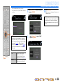
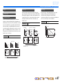
■
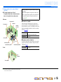
Enjoying the 7.1 channel audio source
without surround back speakers
■ 5.1-channel speaker layout
(5 speakers + subwoofer)
■ Connections of speakers
Connect the speakers to the following jacks according to the
speaker layout. Refer to “Front/Center/Surround/Surround back
speaker and Subwoofer connection” and “Presence speaker
connection” for details on connecting speakers (☞
p. 17).
■ Assigning a speaker configuration
A speaker configuration must be assigned to this unit to activate the
speakers. Use the “Power Amp Assign” function to easily apply the
appropriate speaker settings to this unit according to the speaker
configuration. Speakers for this layout can be activated at the
default “Power Amp Assign” setting (☞
p. 91).
■
Using the front speakers that support bi-
amp connections for a high quality sound
■ 5.1-channel speaker layout
(Front speakers (Bi-amp) + 3 speakers)
■ Connections of speakers
Connect the speakers to the following jacks according to the
speaker layout. Refer to “Front/Center/Surround/Surround back
speaker and Subwoofer connection” and “Bi-amp connection” for
details on connecting speakers (☞
p. 17, p. 18).
■ Assigning a speaker configuration
Use the “Power Amp Assign” function which can easily apply the
appropriate speaker settings to this unit according to the speaker
configuration (☞
p. 91).
This unit can mix 7.1-channel audio source down to 5.1-channel
sound. This enables 7.1-channel sound without surround back
speakers.
Speaker jacks FRONT L/R, CENTER, SURROUND L/R,
SUBWOOFER
EXTRA SP jack No used
Front speaker L
Front speaker R
Subwoofer
Center speaker
Surround speaker L
Surround
speaker R
Power Amp Assign 7ch Normal (Default)
Using the front speakers that support bi-amp connections
reproduces a high quality sound.
Front speaker L
(Bi-amp connection)
Front speaker R
(Bi-amp connection)
Center speaker
Surround speaker L
Surround
speaker R
Subwoofer
Speaker jacks FRONT L/R, CENTER, SURROUND L/R,
SURROUND BACK L/R, SUBWOOFER
EXTRA SP jack No used
Power Amp Assign 5ch BI-AMP
Continues to the
next page

CONNECTIONS
Connecting speakers
En 16
■
Using speakers in two rooms (Zone2
function)
■ 7.1-channel speaker layout + Zone2
(7 speakers (in main zone) + subwoofer (in main
zone) + front speakers (in secondary zone))
Main zone
Zone2
■ Connections of speakers
Connect the speakers to the following jacks according to the
speaker layout. Refer to “Front/Center/Surround/Surround back
speaker and Subwoofer connection” and “Multi-zone audio system
using the internal amplifier of this unit” for details on connecting
speakers (☞
p. 17, p. 18).
■ Assigning a speaker configuration
Use the “Power Amp Assign” function which can easily apply the
appropriate speaker settings to this unit according to the speaker
configuration (☞
p. 91).
Front speaker L
Front speaker R
Center speaker
Subwoofer
Surround
speaker R
Surround speaker L
Surround back speaker L Surround back speaker R
12 in (30 cm) or
more
Front
speaker R
Front speaker L
In addition to the main room, speakers in another room can also
be controlled.
When the built-in amplifier for the speakers in another room is
turned on, the speakers that output the sound are switched from
the surround back speakers to the speakers in another room
automatically. J1
Speaker jacks FRONT L/R, CENTER, SURROUND L/R,
SURROUND BACK L/R, SUBWOOFER
EXTRA SP jack Zone2 speaker
Power Amp Assign 7ch + 1ZONE
J
1 : Sound cannot be output from both the surround back speakers and the speakers
in the second zone at the same time.

CONNECTIONS
Connecting speakers
En 17
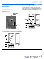
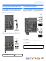
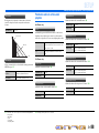
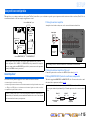
Connecting speakers and subwoofer
Connect your speakers to their respective terminals on the rear panel.
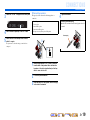
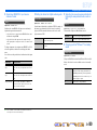
■ Front/Center/Surround/Surround back speaker and
Subwoofer connection
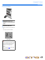
■ Presence speaker connection
When using the presence speakers, connect the speakers to the
EXTRA SP jacks as shown in the diagram below.
The presence speakers (PL/PR) that output front effect sounds can
be connected to this unit. With the sound programs (☞
p. 47),
sound with a richer and more spatial presence can be created.
CAUTION
• Remove the AC power cable of this unit from the power outlet before connecting the speakers.
• Generally speaker cables consist of two parallel insulated cables. One of these cables is a different color, or has a line running along it, to indicate different polarity. Insert the different colored (or lined) cable into the “+”
(positive, red) terminal on this unit and the speakers, and the other cable into the “–” (negative, black) terminal.
• Be careful that the core of the speaker cable does not touch anything or come into contact with the metal areas of this unit. This may damage this unit or the speakers. If the speaker cables short circuit, “CHECK SP
WIRES!” will appear on the front panel display when this unit is switched on.
CENTER
SURROUND
SURROUND BACK/
BI-AMP
SINGLE
FRONT
1
MULTI CH INPUT
MI
1
DVD
)
HDMI
2
HDMI
3
HDMI 4
HDMI
5
E
XTRA
SP
SU
BW
OO
FE
R
A
U
DI
O
OUT
ZO
NE2
OU
T
SU
R.BA
C
K
SU
RR
OU
ND
SURROUND
SUR.BACK
PRE OU
T
W
OOFE
R
2
F
RONT
T
RI
GG
ER
OUT
+12V
0
.1A MAX.
C
ENTE
R
IN
REM
O
TE
OU
T
C
ENTER
S
IN
G
LE
SPEAKERS
SPEAKERS
R
S
-232
C
Z
O
NE2
/
PRE
S
EN
CE
SubwooferCenter speaker
Front speaker Surround
speaker
Surround back
speaker
RL
RL RL
EXTRA SP
ZONE2/PRESENCE
M
I
5
SU
RR
OU
N
D
S
URROUND BACK/
BI
-
AMP
S
IN
G
LE
S
URROUND
SUR.BACK
PRE
OU
T
S
UBWOOFE
R
1
2
C
ENTER
S
IN
G
LE
S
PE
A
SPEA
RS-232
C
Presence speaker
RL
• Connection of presence speakers is recommended to take full
advantage of the effects of CINEMA DSP sound programs.
• Although you can connect both surround back speakers and
presence speakers to this unit, you cannot output sounds from
those speakers at the same time.
0.5 – 1 m 0.5 – 1 m
PL PR
FL FR
1.8 m 1.8 m
Continues to the
next page

CONNECTIONS
Connecting speakers
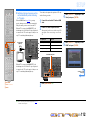
En 18
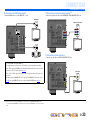
■ Bi-amp connection
This unit can be connected to speakers that support bi-amp
connections. When connecting speakers, connect the FRONT jacks
and the SURROUND BACK/BI-AMP jacks as in the diagram
below. Configure the bi-amp settings to activate connections.
■ Multi-zone audio system using the internal
amplifier of this unit
Connect the speakers in the second zone to the EXTRA SP jacks as
in the diagram below.
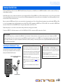
■
Changing speaker impedance
This unit is configured for 8 Ω speakers at the factory setting.
When connecting to 6 Ω speakers, carry out the following
procedure to switch to 6 Ω. When this unit is configured for 6 Ω
speakers, 4 Ω speakers can also be used as the front speakers.
1
Switch this unit to the standby mode.
2
Press MAIN ZONE A while pressing and holding
STRAIGHT on the front panel.
Release the keys when “ADVANCED SETUP” is displayed on
the front panel display.
After approximately a few seconds, the top menu item is
displayed. J1
NOTES
• Before making bi-amplification connections, remove any
brackets or cables that connect a woofer with a tweeter. Refer to
the instruction manuals of speakers for details. When not making
bi-amplification connections, make sure that the brackets or
cables are connected before connecting the speaker cables.
• If connecting a bi-amp, then surround back speakers cannot be
used.
FRONT
SINGLE
SURROUND BACK/
BI-AMP
CAUTION
The EXTRA SP jacks of this unit should not be connected to a
Passive Loudspeaker Selector Box or more than one loudspeaker
per channel.
Connection to a Passive Loudspeaker Selector Box or multiple
speakers per channel could create an abnormally low impedance
load resulting in amplifier damage. See this owner’s manual for
correct usage.
Compliance with minimum speaker impedance information for all
channels must be maintained at all times. This information is found
on the back panel of this unit.
DOCK
(
TV
)
A
V
3
A
V
4
A
V
5
A
V
6
AUDIO 1
AUDIO 2
M
U
L
T
I
C
H
IN
P
U
T
(
CD
)
COAXIAL
OPTICAL
VIDEO
HDMI 1
(
BD/DVD
)
HDMI 2 HDMI 3
HDMI 4 HDMI 5
CENTER
SURROUND
SURROUND BACK/
BI-AMP
SINGLE
EXTRA SP
FRONT
AV
OUT
SUBWOOFER
AUDIO
OUT
ZONE2
OUT
SUR.BACK
SURROUND
SURROUND
SUR.BACK
PRE OUT
SUBWOOFER
1
2
FRONT
TRIGGER OUT
+12V
0.1A MAX.
FRONT
CENTER
IN
REMOTE
OUT
CENTERSINGLE
HDMI OUT
12
ARC ARC
SELECTABLE
SPEAKERSSPEAKERS
ANTENNA
FM
HD Radio
GND
AM
75
OPTICAL
A
V
1
A
V
2
COAXIAL
COMPONENT
VIDEO
P
R
P
B
Y
SIRIUS
RS-232C
COMPONENT
VIDEO
VIDEO
MONITOR OUT
P
R
P
B
Y
ZONE2/PRESENCE
ZONE2/PRESENCE
EXTRA SP
Zone2
PHONES
YPAO MIC
SILENT
CINEMA
TONE
CONTROL
STRAIGHT
TV
BD
DVD
CD
RADIO
INPUT
PROGRAM
SCENE
H
INFOZONE
CONTROL
ZONE2
MAIN ZONE
MEMORY
PRESET
FM AM
CATEGORY
MAIN ZONE A
STRAIGHT
Continues to the
next page
J
1 : Refer to the “Extended functionality that can be configured as needed
(Advanced Setup menu)” (☞
p. 108) for details on the Advanced Setup menu.

CONNECTIONS
Connecting speakers
En 19
3
Check that “SP IMP.” is displayed on the front panel.
4
Press STRAIGHT repeatedly to select a “6ΩMIN.”
5
Switch this unit to the standby mode, and then
switch it on again.
The power turns on, when the settings you made has been
configured.
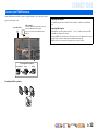
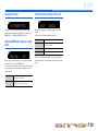
■
Connecting speakers
This type of jack can connect to the following speakers or
connection.
1
Remove approximately 0.4 in. (10 mm) of insulation
from the ends of the speaker cables, and twist the
bare wires of the cables together firmly so that they
will not cause short circuits.
2
Loosen the speaker terminals.
3
Insert the bare wire of the speaker cable into the gap
on the side of the terminal.
4
Tighten the terminal.
SPIMP.-8MIN
• Front L/R speakers
• Center speaker
• Surround L/R speakers
• Surround back L/R speakers
• Bi-amp connection (Front speaker L/R speakers)
FRONT
2
2
3
1
4
4
Connecting the banana plug
Tighten the knob, and then insert the banana plug into the end of
the terminal.
FRONT
Banana plug

CONNECTIONS
Connecting speakers
En 20
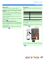
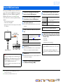
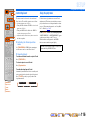
■
Connecting the subwoofer
1
Connect the subwoofer input jack to the
SUBWOOFER 1 or 2 jack on this unit with an audio
pin cable.
2
Set the subwoofer volume as follows.
Volume: Set to approximately half volume (or slightly less than
half).
Crossover frequency (if available): Set to maximum.
NOTE
After connection, applying this setting to this unit is required to
activate all speaker connections. With using “Power Amp
Assign” function, you can easily apply the speaker
configuration.
Refer to “Power Amp Assign” (☞
p. 91) for details on using
“Power Amp Assign” function.
VOLUME
MIN MAX
CROSSOVER/
HIGH CUT
MIN MAX
Subwoofer examples
Strona jest ładowana ...
Strona jest ładowana ...
Strona jest ładowana ...
Strona jest ładowana ...
Strona jest ładowana ...
Strona jest ładowana ...
Strona jest ładowana ...
Strona jest ładowana ...
Strona jest ładowana ...
Strona jest ładowana ...
Strona jest ładowana ...
Strona jest ładowana ...
Strona jest ładowana ...
Strona jest ładowana ...
Strona jest ładowana ...
Strona jest ładowana ...
Strona jest ładowana ...
Strona jest ładowana ...
Strona jest ładowana ...
Strona jest ładowana ...
Strona jest ładowana ...
Strona jest ładowana ...
Strona jest ładowana ...
Strona jest ładowana ...
Strona jest ładowana ...
Strona jest ładowana ...
Strona jest ładowana ...
Strona jest ładowana ...
Strona jest ładowana ...
Strona jest ładowana ...
Strona jest ładowana ...
Strona jest ładowana ...
Strona jest ładowana ...
Strona jest ładowana ...
Strona jest ładowana ...
Strona jest ładowana ...
Strona jest ładowana ...
Strona jest ładowana ...
Strona jest ładowana ...
Strona jest ładowana ...
Strona jest ładowana ...
Strona jest ładowana ...
Strona jest ładowana ...
Strona jest ładowana ...
Strona jest ładowana ...
Strona jest ładowana ...
Strona jest ładowana ...
Strona jest ładowana ...
Strona jest ładowana ...
Strona jest ładowana ...
Strona jest ładowana ...
Strona jest ładowana ...
Strona jest ładowana ...
Strona jest ładowana ...
Strona jest ładowana ...
Strona jest ładowana ...
Strona jest ładowana ...
Strona jest ładowana ...
Strona jest ładowana ...
Strona jest ładowana ...
Strona jest ładowana ...
Strona jest ładowana ...
Strona jest ładowana ...
Strona jest ładowana ...
Strona jest ładowana ...
Strona jest ładowana ...
Strona jest ładowana ...
Strona jest ładowana ...
Strona jest ładowana ...
Strona jest ładowana ...
Strona jest ładowana ...
Strona jest ładowana ...
Strona jest ładowana ...
Strona jest ładowana ...
Strona jest ładowana ...
Strona jest ładowana ...
Strona jest ładowana ...
Strona jest ładowana ...
Strona jest ładowana ...
Strona jest ładowana ...
Strona jest ładowana ...
Strona jest ładowana ...
Strona jest ładowana ...
Strona jest ładowana ...
Strona jest ładowana ...
Strona jest ładowana ...
Strona jest ładowana ...
Strona jest ładowana ...
Strona jest ładowana ...
Strona jest ładowana ...
Strona jest ładowana ...
Strona jest ładowana ...
Strona jest ładowana ...
Strona jest ładowana ...
Strona jest ładowana ...
Strona jest ładowana ...
Strona jest ładowana ...
Strona jest ładowana ...
Strona jest ładowana ...
Strona jest ładowana ...
Strona jest ładowana ...
Strona jest ładowana ...
Strona jest ładowana ...
Strona jest ładowana ...
Strona jest ładowana ...
Strona jest ładowana ...
Strona jest ładowana ...
Strona jest ładowana ...
Strona jest ładowana ...
Strona jest ładowana ...
Strona jest ładowana ...
Strona jest ładowana ...
Strona jest ładowana ...
Strona jest ładowana ...
Strona jest ładowana ...
Strona jest ładowana ...
Strona jest ładowana ...
Strona jest ładowana ...
Strona jest ładowana ...
Strona jest ładowana ...
Strona jest ładowana ...
-
 1
1
-
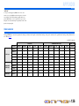
 2
2
-
 3
3
-
 4
4
-
 5
5
-
 6
6
-
 7
7
-
 8
8
-
 9
9
-
 10
10
-
 11
11
-
 12
12
-
 13
13
-
 14
14
-
 15
15
-
 16
16
-
 17
17
-
 18
18
-
 19
19
-
 20
20
-
 21
21
-
 22
22
-
 23
23
-
 24
24
-
 25
25
-
 26
26
-
 27
27
-
 28
28
-
 29
29
-
 30
30
-
 31
31
-
 32
32
-
 33
33
-
 34
34
-
 35
35
-
 36
36
-
 37
37
-
 38
38
-
 39
39
-
 40
40
-
 41
41
-
 42
42
-
 43
43
-
 44
44
-
 45
45
-
 46
46
-
 47
47
-
 48
48
-
 49
49
-
 50
50
-
 51
51
-
 52
52
-
 53
53
-
 54
54
-
 55
55
-
 56
56
-
 57
57
-
 58
58
-
 59
59
-
 60
60
-
 61
61
-
 62
62
-
 63
63
-
 64
64
-
 65
65
-
 66
66
-
 67
67
-
 68
68
-
 69
69
-
 70
70
-
 71
71
-
 72
72
-
 73
73
-
 74
74
-
 75
75
-
 76
76
-
 77
77
-
 78
78
-
 79
79
-
 80
80
-
 81
81
-
 82
82
-
 83
83
-
 84
84
-
 85
85
-
 86
86
-
 87
87
-
 88
88
-
 89
89
-
 90
90
-
 91
91
-
 92
92
-
 93
93
-
 94
94
-
 95
95
-
 96
96
-
 97
97
-
 98
98
-
 99
99
-
 100
100
-
 101
101
-
 102
102
-
 103
103
-
 104
104
-
 105
105
-
 106
106
-
 107
107
-
 108
108
-
 109
109
-
 110
110
-
 111
111
-
 112
112
-
 113
113
-
 114
114
-
 115
115
-
 116
116
-
 117
117
-
 118
118
-
 119
119
-
 120
120
-
 121
121
-
 122
122
-
 123
123
-
 124
124
-
 125
125
-
 126
126
-
 127
127
-
 128
128
-
 129
129
-
 130
130
-
 131
131
-
 132
132
-
 133
133
-
 134
134
-
 135
135
-
 136
136
-
 137
137
-
 138
138
-
 139
139
-
 140
140
-
 141
141


Yamaha RX-A800 Instrukcja obsługi
- Kategoria
- Amplitunery AV
- Typ
- Instrukcja obsługi
w innych językach
- čeština: Yamaha RX-A800 Návod k obsluze
- español: Yamaha RX-A800 El manual del propietario
- italiano: Yamaha RX-A800 Manuale del proprietario
- Deutsch: Yamaha RX-A800 Bedienungsanleitung
- svenska: Yamaha RX-A800 Bruksanvisning
- português: Yamaha RX-A800 Manual do proprietário
- français: Yamaha RX-A800 Le manuel du propriétaire
- English: Yamaha RX-A800 Owner's manual
- dansk: Yamaha RX-A800 Brugervejledning
- русский: Yamaha RX-A800 Инструкция по применению
- suomi: Yamaha RX-A800 Omistajan opas
- Nederlands: Yamaha RX-A800 de handleiding
- română: Yamaha RX-A800 Manualul proprietarului
Powiązane dokumenty
-
Yamaha RX-A2000 Instrukcja obsługi
-
-
Yamaha RX-V671 Instrukcja obsługi
-
-
-
-
-
-
Yamaha RX-V667 instrukcja obsługi
-
