
✂
de Deutsch 2
en English 8
fr Français 14
nl Nederlands 20
pl Polski 26
ru Русский 32
DE 1821515
DE 2427515
DE 5151821
DE 5152427
9000415456
Montage- und
Gebrauchsanleitung
Installation and
operating instructions
Notice de montage
et d’utilisation
Montage- en
gebruikshandleiding
Instrukcja montażu i
użytkowania
Инструкция по монтажу
и эксплуатации

✂
I.
1.
2.
3.
4.
4.
5.
100
1.
3.
2.
388
ca. 96
70
44
100
ca. 72
332
max. 17mm
max. 31mm
ca. 2mm
ca. 16mm
3.
4.
2.
1.
III.
II.

II.
ca. 72
388
ca. 96
70
44
100
332
8.
b+c
7.
b
c
6.
a
b
c
5.
4B
4A
2.
3.
hot
cold
100
1.
AB

III.
2A
2B
a
3.
1.
5.
4.
1.
2.
3.
max. 16 mm
B
ca. 2 mm
A

IV.
7.
6.
1.
5.
3.
2.
3.
4.
5.
7.
warm
hot
chaude
heet
gorący
горячеий
1 Minute entlüften!
Vent for one minute!
Purger pendant une minute !
Gedurende één minuut
ontluchten.
Odpowietrzyć – 1 minutę!
Удалить воздух в
течение 1 минуты!

V.
3.
4.
1.
2.
VI.
7.
6.
4.
5.
min. 40 mm
min. 40 mm
0 mm
PE
L3
L2
L1
2.
3.
RESET
L1
L2
L3
PE
1.
21 kW 27 kW
18 kW 24 kW

✂
A
L 3
L 2
L 1
3
21
PE
PE
B C
1.
2.
3.
D
1.
2.
3.
4.

✂
de
2
Montageanleitung
Montieren Sie den Durchlauferhitzer, wie im Bildteil
beschrieben. Beachten Sie die Hinweise im Text.
Sicherheitshinweise
Stromschlaggefahr!
Schalten Sie im Fehlerfall sofort die Netzspannung
ab.
Wir übernehmen keine Haftung für Schäden, die ■
durch Nichtbeachtung dieser Anleitung entstehen.
Der Durchlauferhitzer darf nur von einem Fachmann ■
angeschlossen und in Betrieb genommen werden.
Öffnen Sie niemals das Gerät, ohne die Stromzufuhr ■
zum Gerät unterbrochen zu haben.
Die gesetzlichen Vorschriften des jeweiligen Landes, des ■
örtlichen Elektrizitäts-Versorgungsunternehmens und des
Wasserwerkes müssen eingehalten werden.
Der Durchlauferhitzer ist ein Gerät der Schutzklasse
■ I und
muss an den Schutzleiter angeschlossen werden.
Das Gerät muss dauerhaft an festverlegte Leitungen an- ■
geschlossen werden. Der Leitungsquerschnitt muss der
zu installierenden Leistung entsprechen.
Vorsicht ■ : Geerdete Wasserleitungen können das Vorhan-
densein eines Schutzleiters vortäuschen.
Nur für Österreich: Bei Verwendung der Schutzmaßnah-
■
me „Fehlerstrom-Schutzschaltung“ (sowohl bei bereits
in Ihrer Installation vorhandenem Fehlerstrom-Schutz-
schalter als auch bei Neuinstallation Ihrer Anlage) darf in
Verbindung mit diesem Gerät nur ein pulsstromsensitiver
Fehlerstrom-Schutzschalter vorgeschaltet werden.
Zur Erfüllung der einschlägigen Sicherheitsvorschriften
■
muss installationsseitig eine allpolige Trennvorrichtung
vorhanden sein. Die Kontaktöffnung muss mindestens
3 mm betragen.
Der Durchlauferhitzer ist nur für den geschlossenen ■
(druckfesten) Betrieb geeignet.
Armaturen müssen für den Betrieb mit geschlossenen ■
(druckfesten) Durchlauferhitzern zugelassen sein.
Der Durchlauferhitzer kann an eine Kaltwasserleitung ■
angeschlossen oder mit vorgewärmtem Wasser (Solar-
anlage) betrieben werden. Dazu technische Daten und
Sonderzubehör beachten.
Der Durchlauferhitzer ist für den Anschluss an DVGW- ■
geprüfte Kunststoffrohre geeignet.
Den Durchlauferhitzer nur in einem frostfreien Raum ■
installieren.
Das elektrische Anschlusskabel vor der Montage span- ■
nungslos machen und die Wasserzuleitung absperren!
Den Elektroanschluss erst nach dem Wasseranschluss ■
durchführen.
In der Rückwand nur die Öffnungen herstellen, die für ■
die Montage benötigt werden. Bei erneuter Montage
müssen die unbenutzten Öffnungen wasserdicht ver-
schlossen werden.
Spannungsführende Teile dürfen nach der Montage nicht
■
mehr berührbar sein
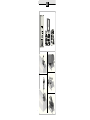
Montage
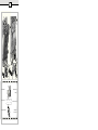
I.
Auspacken/Haube abnehmen
Gerät auspacken und auf Transportschäden kontrollieren. ■
Verpackung und gegebenenfalls Altgerät umweltgerecht ■
entsorgen.
II.
Montagevorbereitung
Wichtig: Nur den beiliegenden Montagesatz verwenden.
Die mitgelieferten Wasseranschlussstutzen müssen unbedingt
eingebaut werden!
Wasserzuleitung absperren. Der elektrische Anschluss
■
(Anschlusskabel) muss spannungsfrei sein. Sicherungen
herausdrehen oder ausschalten.
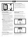
III.
Wandmontage
Der Durchlauferhitzer muss fest an der Wand montiert ■
werden. Befestigen Sie ihn gegebenenfalls an den unte-
ren Stellschrauben.
Der Wandabstand ist variabel. So können Unebenheiten
■
der Wand ausgeglichen werden.
Die Tülle muss das Anschlusskabel eng umschließen. ■
Wird sie bei der Montage beschädigt, müssen die Löcher
wasserdicht verschlossen werden.
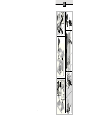
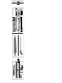
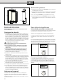
IV.
Wasseranschluss
Der Durchlauferhitzer muss entlüftet werden. Dazu ■
Warmwasserhahn ganz öffnen und das Gerät 1 Minute
mit einer Durchflussmenge von mindestens 6 Liter
Wasser durchspülen.
V.
Elektroanschluss/Montage
Die Netzanschlussklemme kann oben oder unten mon- ■
tiert werden. Die Ummantelung des Anschlusskabels
muss mindestens 40 mm in das Gerät hineinragen.
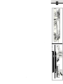
Vor Anschluss der Leitungen an die Netzanschlussklemme
die Leistung mit dem Leistungsumschalter einstellen:
DE 1821515 und DE 5151821 auf 18 kW (unten) oder
■
21 kW (oben) stellen.
DE 2427515 oder DE 5152427 auf 24 kW (unten) oder ■
27 kW (oben) stellen.
Die eingestellte Leistung muss am Typenschild markiert
werden.
Anschließend die Leitungen an die Netzanschlussklemme ■
festschrauben.

3
de
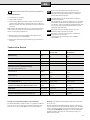
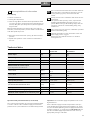
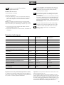
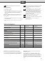
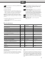
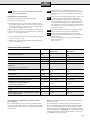
Technische Daten
DE 1821515
DE 5151821
DE 2427515
DE 5152427
Nennleistung
[kW]
18
21
24
27
Nennspannung
[V] 400 400
Absicherung
[A] 32 40
Mindestens Leitungsquerschnitt
[mm
2
]4 6
Warmwassermenge bei Nennleistung
bei Temperaturerhöhung von
12 °C auf 38 °C [l/min]
9,9
11,6
13,2
13,9
12 °C auf 60 °C [l/min]
5,4
6,3
7,2
7,6
Einschaltmenge
[l/min] 2,6 2,6
Einschaltfließdruck *
[MPa (bar)] 0,025 (0,25) 0,025 (0,25)
Einsatzbereich in Wässern
Spezifischer elektrischer Widerstand bei 15 °C
[Ωcm] ≥ 1 300 ≥ 1 300
Nenndruck
[MPa (bar)] 1,0 (10,0) 1,0 (10,0)
Maximal zulässige Zulauf-Temperatur
[°C] 55 55
Maximale Netzimpedanz am Anschlussort
[Ω] ≤ 0,44 ≤ 0,244
* Hierzu kommt noch der Druckabfall an der Mischbatterie
Betrieb mit vorgewärmtem Wasser (Solarbetrieb)
Der Durchlauferhitzer erwärmt bereits vorgewärmtes Wasser
auf max. 60 °C. Überschreitet der Kaltwasserzulauf die Tem-
peratur von 55 °C, wird das Wasser nicht weiter erwärmt.
Wichtig: Die Kaltwasser-Zulauftemperatur darf nicht höher
als 55 °C sein!
Wird die Kaltwasser-Zulauftemperatur von 60 °C überschrit-
ten, löst das Gerät eine Sicherheitsabschaltung aus. Deshalb
muss in der Hausinstallation ein Thermostatvormischer (z. B.
Sonderzubehör BZ 45T20) eingebaut sein, der die Kaltwasser-
Zulauftemperatur auf max. 55 °C durch Zumischung von
Kaltwasser begrenzt.
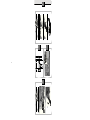
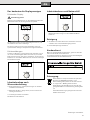
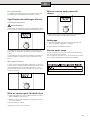
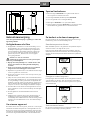
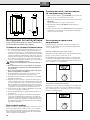
VI.
Inbetriebnahme/Zusatzinformationen
Erstinbetriebnahme
Sicherungen einschalten.
■
Temperatur einstellen. ■
Startspülung: Warmwasserhahn öffnen und mindestens ■
1 Minute lang (Durchfluss mindestens 6 Liter pro Minute)
Wasser beziehen. Erst dann (Sicherheit) beginnt das Gerät
zu heizen.
Tipp: Startet das Gerät aufgrund von zu geringem Durchfluss
nicht, Perlator, Brausekopf oder ähnliches zum Starten ent-
fernen und Vorgang wiederholen.
Entfernen Sie bei niedrigem Wasserleitungsdruck den
■
Durchflussbegrenzer (siehe Bild A).
Erklären Sie dem Benutzer die Bedienung des Durchlauf-
■
erhitzers.
A
Erreicht der Durchlauferhitzer aufgrund von zu
geringem Wasserleitungsdruck in Ihrer Hausinstal-
lation keinen genügenden Durchfluss, entfernen
Sie den Durchflussbegrenzer.
B
Vorrangschaltung für die Kombination mit Elektro-
Speicherheizgeräten:
Für den Betrieb mit Vorrangschaltung ist ein spezielles
Lastabwurfrelais BZ 45L20 (Sonderzubehör) erforder-
lich. Andere, bereits vorhandene Lastabwurfrelais, aus-
genommen elektronische Lastabwurfrelais, können
Fehlfunktionen aufweisen.
C
Bei Betrieb mit dem Lastabwurfrelais muss die
Regelungs elektronik kodiert werden.
D
Das Sieb vor dem Rückschlagventil im Kaltwasser-
zulaufstutzen ist verstopft.
Sieb entnehmen und reinigen oder entkalken.
Siehe Bild D 1–3.

4
de
Gebrauchsanleitung
Bevor Sie das Gerät benutzen, lesen Sie bitte sorgfältig
diese Gebrauchsanleitung!
Sicherheitshinweise
Dieses Gerät ist für den Haushalt oder für haushalts- ■
ähnliche, nicht-gewerbliche Anwendungen bestimmt.
Haushaltsähnliche Anwendungen umfassen z. B. die Ver-
wendung in Mitarbeiterküchen von Läden, Büros, land-
wirtschaftlichen und anderen gewerblichen Betrieben,
sowie die Nutzung durch Gäste von Pensionen, kleinen
Hotels und ähnlichen Wohneinrichtungen.
Stromschlaggefahr!
Schalten Sie im Fehlerfall sofort die Netzspannung ab.
Wir übernehmen keine Haftung für Schäden, die durch ■
Nichtbeachtung dieser Anleitung entstehen.
Der Durchlauferhitzer darf nur von einem Fachmann
■
angeschlossen und in Betrieb genommen werden.
Reparaturen dürfen nur von einem Fachmann durchge-
■
führt werden, um Gefährdungen zu vermeiden.
Der Durchlauferhitzer muss in einem frostfreien Raum
■
installiert werden.
Personen (auch Kinder) mit verminderten körperlichen
■
Sinneswahrnehmungs- oder geistigen Fähigkeiten oder
mit mangelnder Erfahrung und Wissen, das Gerät nicht
bedienen lassen, außer sie werden beaufsichtigt oder hat-
ten eine Einweisung bezüglich des Gebrauchs des Gerätes
durch eine Person, die für ihre Sicherheit verantwortlich ist.
Kinder vom Gerät fernhalten. Kinder beaufsichtigen, um
■
zu verhindern, dass sie mit dem Gerät spielen.
Die Mischbatterie und das Warmwasserrohr können heiß
■
werden.
Im Störungsfall bitte sofort die Sicherungen ausschalten.
■
Bei einer Undichtigkeit am Gerät sofort die Kaltwasser-
zuleitung schließen. Die Störung nur durch den Werks-
kundendienst oder einen anerkannten Fachbetrieb
beheben lassen.
Ihr neues Gerät
Der elektronische Durchlauferhitzer „electronic comfort plus“
erwärmt das Wasser, während es durch das Gerät fließt.
Der Durchlauferhitzer schaltet sich ein und erhitzt das Wasser,
wenn der Warmwasserhahn geöffnet wird. Er schaltet sich
wieder aus, wenn Sie den Wasserhahn schließen.
So bedienen Sie den
Durchlauferhitzer
Die Grundeinstellung der Wassertemperatur nach Erstin-
betriebnahme oder Netzausfall beträgt 40 °C.
Duschtemperatur wählen
Mit dem Drehknopf wählen Sie die gewünschte Temperatur
stufenlos von 20 °C bis 60 °C in Schritten von 0,5 °C aus.
Info: Die im Display angezeigte Temperatur zeigt die Wasser-
temperatur im Gerät an. Durch Rohrleitungsverluste kann die
Wassertemperatur am Wasserauslauf davon abweichen.
Energie- und Wassersparen
Das Zumischen von Kaltwasser an der Armatur verbraucht
unnötig Wasser und Energie. Stellen Sie die gewünschte
Temperatur deshalb direkt am Durchlauferhitzer ein und
öffnen den Warmwasserhahn.
Vorgewärmtes Wasser
Der Durchlauferhitzer kann mit vorgewärmtem Wasser
(zum Beispiel aus der Solaranlage) betrieben werden.
Sonderzubehör
Rohrbausatz
■ BZ 45U20: zur Verwendung des Durchlauf-
erhitzers als Untertischgerät
Vorrangschalter (Lastabwurfrelais) ■ BZ 45L20:
für den Betrieb mit Vorrangschaltung
Montageset ■ BZ 45K23: für Aufputzinstallation
Thermostatvormischer ■ BZ 45T20: für den Einbau in die
Hausinstallation bei Nutzung von vorgewärmtem Wasser
G
1
2
A
472
99
115
236
20
100
332
42
388

5
de
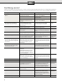
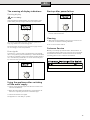
Das bedeuten die Displayanzeigen
Blinkendes Display
Verbrühungsgefahr!
Blinkt die Temperaturanzeige, ist die Auslauftemperatur am
Wasserhahn höher als die eingestellte Temperatur.
Die Zulauftemperatur aus der Hausanlage ist zu hoch, z. B.
durch Wasser aus einer Solaranlage.
Der Thermostatvormischer in der Hausanlage muss ent-
sprechend auf niedrigere Temperaturen eingestellt werden.
Fehlermeldungen
Leuchtet im Display z. B. E02 (oder E03 bis E14) auf, liegt es
oft nur an einer Kleinigkeit. Bitte versuchen Sie, wie unter
Kapitel „Eine Störung, was tun?“ beschrieben, die Störung zu
beheben. Sie vermeiden dadurch Kosten für einen unnötigen
Kundendiensteinsatz.
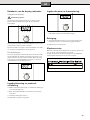
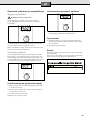
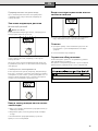
Inbetriebnahme nach
Wasserabschaltung
Gerät spannungslos machen (Sicherungen in der Haus-
■
installation ausschalten).
Warmwasserhahn so lange öffnen, bis die Luft aus der ■
Leitung entwichen ist.
Sicherungen wieder einschalten. ■
Das Gerät ist betriebsbereit.
Inbetriebnahme nach Netzausfall
Den Warmwasserhahn ganz öffnen und mit einer ■
Mindest durchflussmenge von 6 Liter/Minute Wasser
beziehen.
Reinigung
Das Gerät nur feucht abwischen. Verwenden Sie keine
■
scharfen oder scheuernden Reinigungsmittel.
Keinen Dampfreiniger benutzen. ■
Kundendienst
Wenn Sie den Kundendienst anfordern, geben Sie bitte die
E-Nr. und die FD-Nr. Ihres Gerätes an.
Sie finden die Nummern auf der Innenseite der aufklappba-
ren Bedienblende des Durchlauferhitzers.
Entsorgung
Dieses Gerät ist entsprechend der europäischen
Richtlinie 2002/96/EG über Elektro- und
Elektronik- Altgeräte (waste electrical and electro-
nic equipment – WEEE) gekennzeichnet.
Die Richtlinie gibt den Rahmen für eine EU-weit
gültige Rücknahme und Verwertung der Altgeräte
vor.
Über aktuelle Entsorgungswege bitte beim Fach-
händler informieren.
Änderungen vorbehalten.

6
de
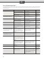
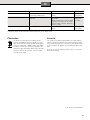
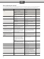
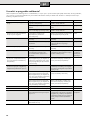
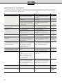
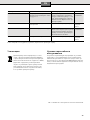
Eine Störung, was tun?
Funktioniert Ihr Gerät nicht wie gewünscht, so liegt es oft nur an einer Kleinigkeit. Bitte prüfen Sie, ob aufgrund folgender Hin-
weise die Störung selbst behoben werden kann. Sie vermeiden dadurch die Kosten für einen unnötigen Kundendiensteinsatz.
Störung Ursache Behebung Wer
Zu geringer Durchfluss von
Wasser.
Das Sieb im Wasserhahn oder im
Duschkopf ist verstopft.
Das Sieb entnehmen und
reinigen oder entkalken.
Kunde
Das Sieb im Heizblock ist verstopft. Das Sieb durch einen Fachmann
reinigen lassen.
Fachmann
Das Sieb vor dem Rückschlagventil
im Kaltwasserzulaufstutzen ist
verstopft.
Das Sieb entnehmen und
reinigen oder entkalken.
Fachmann
Die eingestellte hohe Wasser-
temperatur wird nicht erreicht.
Der Durchlauferhitzer ist an
eine Thermostat-Mischbatterie
angeschlossen.
Die Temperatur am Durchlauf-
erhitzer auf „60 °C“ einstellen.
Kunde
Keine Displayanzeige Die Sicherung in der Haus-
installation hat ausgelöst.
Die Sicherung in der Haus-
installation überprüfen.
Kunde
Der Sicherungsautomat im Gerät
hat ausgelöst.
Den Sicherungsautomaten im Gerät
durch einen Fachmann überprüfen
lassen.
Fachmann
Das Wasser wird nicht warm. Die Sicherung in der Haus-
installation hat ausgelöst.
Die Sicherung in der Haus-
installation überprüfen.
Kunde
Es fließt kurzzeitig kaltes Wasser. Die Lufterkennung im Gerät regis-
triert Luft im Wasser und schaltet
die Heizleistung kurzzeitig ab.
Der Durchlauferhitzer geht nach
einigen Sekunden automatisch
wieder in Betrieb.
Automatik
im Durchlauf-
erhitzer
Die eingestellte Temperatur, z. B.
41,0 °C, blinkt. Die Auslauftempe-
ratur ist höher als die eingestellte
Temperatur.
Die Zulauftemperatur im Durch-
lauferhitzer ist höher als die ein-
gestellte Temperatur (z. B. durch
vorgewärmtes Wasser aus der
Solaranlage).
Der Thermostatvormischer in der
Hausanlage muss entsprechend auf
niedrigere Temperaturen eingestellt
werden.
Kunde
Winterbetrieb: Die gewünschte
Auslauftemperatur wird im Win-
ter nicht mehr erreicht.
Die Zulauftemperatur ist gesunken.
Wassermenge am Wasserhahn so
weit reduzieren, bis die gewünschte
Warmwassertemperatur erreicht wird.
Kunde
E02 Kein Thermostatvormischer
vorhanden
Die Zulauftemperatur zum Durch-
lauferhitzer ist höher als 55 °C
(z. B. durch vorgewärmtes Wasser
aus der Solaranlage).
Thermostatvormischer in die
Hausanlage einbauen.
Kunde
Die Zulauftemperatur zum Durch-
lauferhitzer ist höher als 55 °C
(z. B. durch vorgewärmtes Wasser
aus der Solaranlage).
Der Thermostatvormischer in der
Hausanlage muss entsprechend auf
niedrigere Temperaturen eingestellt
werden.
E03–E04 Temperatursensor defekt Bitte den Kundendienst anrufen.
Kundendienst
E05–E07 Elektronik defekt Bitte den Kundendienst anrufen.
Kundendienst
E08 Frostschaden
Der Zulaufsensor misst eine
Temperatur von ≤ 0 °C.
Das Gerät ist defekt! Unbedingt
sofort das Wasser abdrehen und
das Gerät vom Strom trennen
(siehe auch Sicherheitshinweise).
Bitte den Kundendienst anrufen.
Kunde/
Fachmann
E09 Temperatursensor/
Elektronik defekt
Bitte den Kundendienst anrufen.
Kundendienst
E10–E11 Luftblasenerkennung spricht an. Das Gerät vom Strom trennen.
Den Warmwasserhahn zum Ent-
lüften ganz öffnen und das Gerät
1 Minute lang durchspülen. Strom
wieder einschalten.
Kunde/
Fachmann
E12–E13 Elektronik defekt Bitte den Kundendienst anrufen.
Kundendienst
Konnte die Störung nicht behoben werden, bitte den Kundendienst anrufen.

7
de
08/09

8
en
Installation instructions
Install the continuous-flow heater as described in the
illustrated section. Observe the instructions in the text.
Safety information
Risk of electric shock!
Switch off the mains voltage supply immediately if
a fault occurs.
We do not accept liability for damage resulting from
■
failure to heed these instructions.
The continuous-flow heater may only be connected ■
and put into operation by a qualified professional.
Never open the appliance without disconnecting the ■
power supply beforehand.
The statutory regulations of the respective country, as ■
well as those of the local electricity and water suppliers,
must be adhered to.
The continuous-flow heater is a Class ■ I appliance and
must be connected to the protective earth.
The appliance must be permanently connected to installed
■
pipes. The conductor cross-section must comply with
the installed appliance power.
Caution
■ : Earthed water pipes may give the appearance of
a connected protective earth.
To guarantee compliance to relevant safety regulations,
■
an all-pole separator must be fitted during installation.
The contact opening must be at least 3 mm.
The continuous-flow heater is only suitable for closed
■
(pressurized) operation.
The tap and outlet fittings must be approved for operation ■
with closed (pressurized) continuous-flow heater systems.
The continuous-flow heater can be operated with cold or ■
pre-warmed water (for example, from a solar energy unit
water supply). Observe the technical data and the special
accessories for this purpose.
The continuous-flow heater is only suitable for connection
■
to DVGW (German Technical and Scientific Association for
Gas and Water) approved plastic pipes.
The continuous-flow heater may only be installed in a ■
frost-free room.
Disconnect the electrical connection cable from the
■
supply and shut off the water supply before connect-
ing the appliance!
Connect the water supply and then connect the elec-
■
trical supply.
Only make the openings which are required for instal-
■
lation on the rear of the appliance. If the appliance is
reinstalled, the unused openings must be provided with
watertight sealing.
Do not touch electrically live parts after installation.
■
Installation
I.
Unpacking/Removing the cover
Unpack the appliance and check for transport-related ■
damage.
Please dispose of the packaging, and if applicable, the old
■
appliance in an environmentally-friendly manner.
II.
Preparations for installation
Important: Only use the supplied installation set.
The supplied water connection nozzles must be installed!
Shut off water supply. The electrical connection (connec-
■
tion cable) must be disconnected from the power supply.
Unscrew the fuse or switch off the circuit breaker.
III.
Wall mounting
The continuous-flow heater must be mounted on the ■
wall. Attach it if necessary on the lower adjustable screws.
The distance to the wall is variable. You can compensate
■
for any unevenness of the wall's surface.
The grommet must tightly surround the connection cable.
■
If it is damaged during mounting, the openings must be
provided with watertight sealing.
IV.
Water connection
The continuous-flow heater must be vented. The ■
warm water tap must be opened and the appliance
must be flushed out thoroughly for 1 minute with
at least 6 litres of water.
V.
Electrical connection/Mounting
The electrical supply terminal can be fitted at the top or ■
bottom. The sheath of the connection cable must extend
for at least 40 mm into the appliance.
Set the power using the power selector switch before
connecting the wires to the mains connection terminal:
Set DE 1821515 and DE 5151821 to 18 kW (down) or
■
21 kW (up).
Set DE 2427515 or DE 5152427 to 24 kW (down) or
■
27 kW (up).
The set power must be marked on the ratings plate.
Now screw the wires tightly into the mains connection
■
terminal.

9
en
Technical data
DE 1821515
DE 5151821
DE 2427515
DE 5152427
Rated output
[kW]
18
21
24
27
Rated voltage
[V] 400 400
Fuse protection
[A] 32 40
Minimum conductor cross-section
[mm
2
]4 6
Warm water flow at rated output
with temperature increase from
12 °C to 38 °C [l/min]
9.9
11.6
13.2
13.9
12 °C to 60 °C [l/min]
5.4
6.3
7.2
7.6
Start-up flow
[l/min] 2.6 2.6
Start-up flow pressure *
[MPa (bar)] 0.025 (0.25) 0.025 (0.25)
Application area in water
specific electric resistance at 15 °C
[Ωcm] ≥ 1 300 ≥ 1 300
Rated pressure
[MPa (bar)] 1.0 (10.0) 1.0 (10.0)
Maximum permissible supply temperature
[°C] 55 55
Maximum mains impedance at connection point
[Ω] ≤ 0.44 ≤ 0.244
* The pressure loss on the mixer must also be added
Operation with prewarmed water (solar heated)
The continuous-flow heater can only heat prewarmed water
to a max. of 60 °C. If the cold water supply exceeds a tem-
perature of 55 °C, the water will not be warmed any further.
Important: The cold water supply temperature must not be
higher than 55 °!
If the cold water supply exceeds a temperature of 60 °C, a
circuit breaker will trigger and shut the appliance off. There-
fore, the residential plumbing must be equipped with a ther-
mostatic premixer (e. g. special accessory BZ 45T20) that will
limit the cold water supply temperature to a max. of 55 ° by
appropriately mixing in cold water.
VI.
Startup/additional information
First start-up
Switch on the fuses.
■
Setting the temperature. ■
Starts rinsing: Open the warm water tap and allow water ■
to flow for at least 1 minute (flow-rate at least 6 litres per
minute). Only then (for safety reasons) will the appliance
begin to heat.
Tip: Should the appliance not start because of a reduced
flow-rate, remove the perlator, shower head or similar before
start and repeat the process.
Remove the flow-rate limiter (see Fig. A) with low water
■
pressure.
Explain the operation of the continuous-flow heater to
■
the user.
A
If the continuous-flow heater does not have sufficient
water flow due to low water line pressure in your do-
mestic plumbing system, remove the flow-rate
limiter.
B
Priority circuit for the combination with electrical stor-
age heaters:
For operation with a priority circuit, a special load
shedding relay BZ 45L20 (special accessory) is re-
quired. Other existing load shedding relays, with the
exception of electronic load shedding relays, may
malfunction.
C
The control electronics must be coded when operated
with a load shedding relay.
D
The filter upstream from the check valve in the cold
water supply inlet is clogged.
Remove the filter and either clean it or descale it.
See Figure D 1–3.

10
en
Operating instructions
Please read the operating instructions carefully before
you use the appliance!
Safety information
This appliance is intended for domestic use or for house-
■
hold-based non-commercial applications. Household-
based applications include, e.g. usage in employees
catering facilities for shops, offices, agricultural and
other commercial operations, as well as usage by guests
of guest houses, small hotels and similar residential
establishments.
Risk of electric shock!
Switch off the mains voltage supply immediately if
a fault occurs.
We do not accept liability for damage resulting from
■
failure to heed these instructions.
The continuous-flow heater may only be connected
■
and put into operation by a qualified professional.
Repairs may only be undertaken by a suitably qualified
■
specialist to avoid potential sources of danger.
The continuous-flow heater may only be installed in a
■
frost-free room.
Persons (including children) with diminished bodily, sen-
■
sory or mental perception, or those who lack knowledge or
experience should not operate the appliance, unless they
are monitored or have received instruction concerning use
of the appliance by persons responsible for their safety.
Keep children away from the appliance. Please moni-
■
tor children to ensure that they do not play with the
appliance.
The mixer and the warm water pipe may be hot.
■
Please switch off all fuses immediately if a malfunction ■
occurs. Immediately shut off the cold water supply to the
appliance should it leak. The malfunction can only be re-
paired by a specialist or an authorised service agent.
Your new appliance
The electronic continuous-flow heater “electronic comfort
plus” is intended exclusively for heating water which flows
through the appliance.
The continuous-flow heater switches on and heats the water
when the warm water tap is opened. It switches off as soon as
the tap is closed.
Operating the continuous-flow
heater
The default temperature for the water temperature after
setting the first start-up or a power failure is 40 °C.
Selecting shower temperature
Select the required temperature with the rotary knob used to
vary the desired temperature from 20 °C to 60 °C in steps of
0.5 °C.
Info: The temperature shown in the display is the water tem-
perature inside the appliance. The temperature of the water
leaving the tap can vary from this due to heat losses in the
pipework.
Conserving energy and water
Mixing in of cold water in the fitting requires unnecessary
water and energy. You should therefore set the desired tem-
perature directly on the continuous-flow heater and then
open the water tap.
Pre-warmed water
The continuous-flow heater can be operated with pre-
warmed water (for example from a solar energy unit).
Special accessories
Pipe kit ■ BZ 45U20: for use of the continuous-flow heater
as an under sink appliance
Priority switch (load shedding relay)
■ BZ 45L20:
for operation with a priority circuit
Mounting kit ■ BZ 45K23: for surface mount installation
Thermostatic premixer ■ BZ 45T20: for installation in the
domestic plumbing when using preheated water
G
1
2
A
472
99
115
236
20
100
332
42
388

11
en
The meaning of display indications
Flashing display
Risk of scalding!
If the temperature display flashes, the temperature of the
water leaving the tap is higher than the set temperature.
The supply temperature from the domestic system is too
high, e. g. water from a solar energy unit.
The thermostatic premixer in the domestic supply must be
set accordingly to lower temperatures.
Error signals
Sometimes e. g. E02 (or E03 to E14) appears in the display
due to a very minor problem. Please try to eliminate the fault
according to guidelines given in the chapter "A fault, what to
do?". You will save yourself the cost of an unnecessary visit
by customer service personnel.
Using the appliance after switching
off the water supply
Switch off the appliance (unscrew the fuse in the house
■
electrical installation).
Open the warm water tap and keep it open until the air ■
has been completely forced out of the water pipe.
Switch the fuse back on again. ■
The appliance is now ready to operate.
Start-up after power failure
Open the warm water tap fully and allow a minimum wa- ■
ter flow of 6 litres/minute.
Cleaning
Only wipe off the appliance using a moist cloth. Do not ■
use acidic or abrasive cleaning materials.
Do not use a steam cleaner. ■
Customer Service
We ask you to always provide the E-No. and the FD-No. of
your appliance when calling in a customer service engineer.
You will find the numbers on the inner side of the fold up
operating panel on the continuous-flow heater.

12
en
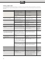
A fault, what to do?
If your appliance does not operate as required, it is often due to a very minor problem. Please check whether you can remedy
the fault yourself by using the following guidelines. You will save yourself the costs of an unnecessary visit by customer service
personnel.
Fault Cause Solution Who
Water flow-rate is too low. The filter in either the water tap or
the showerhead is clogged.
Remove the filter and either
clean it or descale it.
Customer
The filter in the corner regulating
valve is clogged.
Get a servicing expert to clean the
filter.
Servicing
expert
The filter upstream from the check
valve in the cold water supply inlet
is clogged.
Remove the filter and either
clean it or descale it.
Servicing
expert
The desired water temperature is
set, but it is not reached.
The continuous-flow heater is
connected to a thermostatically-
controlled water faucet.
Set the temperature on the continu-
ous-flow heater to “60 °C”.
Customer
The display is blank The fuse in the house electrical in-
stallation has triggered/blown.
Check the fuse in the house electri-
cal installation.
Customer
The appliance's automatic circuit
breaker has been tripped.
Get the appliance's automatic
circuit breaker checked by an
electrician.
Servicing
expert
The water is not warm. The fuse in the house electrical in-
stallation has tripped/blown.
Check the fuse in the house electri-
cal installation.
Customer
From time to time, cold water
flows out.
The air sensor in the appliance de-
tects air in the water and momen-
tarily switches the heating element
off.
After a few seconds, the continu-
ous-flow heater automatically goes
back into operation.
Continuous-
flow heater
automati-
cally resolves
problem
The set temperature, for instance
41.0 °C flashes. The temperature
of the water leaving the tap is
higher than the set temperature.
The temperature of the water
supplying the continuous-flow
heater is higher than the set tem-
perature (e. g. due to pre-warmed
water supplied from a solar water
heater).
The thermostatic premixer in the
domestic supply must be set ac-
cordingly to lower temperatures.
Customer
Winter operation:The desired wa-
ter temperature leaving the tap is
no longer reached.
The supply temperature has
reduced.
Reduce the water flow on the taps
until the desired water temperature
is reached.
Customer
E02 No thermostatic premixer available
The supply temperature to the
continuous-flow heater is higher
than 55 °C (e. g. due to pre-warmed
water supplied from a solar water
heater).
Install a thermostatic premixer in
the domestic supply.
Customer
The supply temperature to the
continuous-flow heater is higher
than 55 °C (e. g. due to pre-warmed
water supplied from a solar water
heater).
The thermostatic premixer in the
domestic supply must be set ac-
cordingly to lower temperatures.
E03–E04 Temperature sensor defective Please contact customer service. Customer
Service
E05–E07 Electronic malfunction Please contact customer service. Customer
Service
E08 Frost damage
The water supply sensor measures
a temperature on ≤ 0 °C.
The appliance is defective! Switch
off the water supply immediately
and disconnect the appliance from
the electrical supply (also refer to
the safety instructions)
Please contact customer service.
Customer/
Servicing
expert

13
en
Guarantee
The guarantee conditions for this appliance are as defined by
our representative in the country in which it is sold.
Details regarding these conditions can be obtained from the
dealer from whom the appliance was purchased. The bill of
sale or receipt must be produced when making any claim un-
der the terms of this guarantee.
Subject to change without notice.
Disposal
This appliance is labelled in accordance with Euro-
pean Directive 2002/96/EG concerning used elec-
trical and electronic appliances (waste electrical
and electronic equipment – WEEE).
The guideline determines the framework for the
return and recycling of used appliances as applica-
ble throughout the EU.
Please ask your specialist retailer about current
disposal facilities.
If the fault could not be eliminated, please call customer service.
Fault Cause Solution Who
E09 Temperature sensor/
electronics defective
Please contact customer service. Customer
Service
E10–E11 Bubble detection triggers. Disconnect the appliance from the
electrical supply.
Open the warm water tap fully for
venting purposes and flush out the
appliance thoroughly for 1 minute.
Switch the power back on again.
Customer/
Servicing
expert
E12–E13 Electronic malfunction Please contact customer service. Customer
Service

14
fr
Instructions de montage
Montez le chauffe-eau instantané en suivant les indica-
tions portées sur les figures. Respectez les consignes du
texte.
Consignes de sécurité
Danger de choc électrique !
En cas d’erreur, déconnectez immédiatement
la tension du secteur.
Nous n’assumons aucune garantie pour les risques
■
susceptibles de survenir en cas de non-respect de
cette notice.
Seul un installateur agréé est autorisé à raccorder ■
et à mettre en marche le chauffe-eau instantané.
N’ouvrez jamais l’appareil sans avoir interrompu ■
l’apport de courant à l’appareil.
Respectez les prescriptions légales en vigueur dans votre ■
pays ainsi que celles recommandées par les compagnies
locales/nationales distributrices d’électricité et d’eau et
applicables dans votre localité.
Le chauffe-eau instantané est un appareil qui répond à la ■
classe de protection I. Il doit être raccordé au fil de terre.
L’appareil doit être raccordé de manière durable aux ■
conduites d’eau posées de manière fixe. La section de
câble doit correspondre à la puissance à installer.
Exemple
■ : Les conduites d’eau mises à la terre peuvent
simuler la présence d’un fil de terre.
Afin de respecter les prescriptions de sécurité applicables,
■
l’installation doit comporter un dispositif de coupure tous
pôles. L’espace coupe-circuit entre les contacts doit s’éle-
ver à 3 mm minimum.
Le chauffe-eau est conçu uniquement pour fonctionner
■
en circuit fermé (résistant à la pression).
La robinetterie doit pouvoir s’utiliser avec des chauffe-eau ■
fermés (résistants à la pression).
Le chauffe-eau instantané peut être raccordé à une ■
conduite d’eau froide ou être exploité avec l’eau préchauf-
fée (installation solaire). Pour ce, respecter les données
techniques et les accessoires spéciaux.
Le chauffe-eau peut s’utiliser avec de la tuyauterie en
■
matière plastique certifiée DVGW.
Installez le chauffe-eau uniquement dans un local
■
exempt de gel.
Avant le montage, mettez le câble d’alimentation
■
électrique hors tension et coupez l’arrivée d’eau !
Procédez d’abord au raccordement de l’eau, puis au ■
raccordement électrique.
Pratiquez dans la paroi arrière uniquement les ouvertures
■
nécessaires au montage. Si vous refaites le montage, bou-
chez les ouvertures inutilisées afin de les rendre étanches.
Une fois le montage terminé, les pièces électroconductri-
■
ces doivent être impossibles à toucher.
Montage
I.
Déballage/enlèvement du capot
Déballez l’appareil et vérifiez s’il n’a pas subi de dégâts ■
pendant le transport.
Eliminez l’emballage et, le cas échéant, l’ancien appareil
■
en respectant l’environnement.
II.
Préparation du montage
Important : n’utilisez que le kit de montage joint.
Les tubulures de raccordement d’eau livrées doivent être
impérativement montées !
Coupez l’arrivée d’eau. Le raccord électrique (câble de
■
raccordement) doit être sans tension. Dévissez ou désen-
clenchez les fusibles.
III.
Montage mural
Le chauffe-eau instantané doit être solidement monté ■
contre le mur. Fixez-le le cas échéant au moyen des vis
de réglage inférieures.
L’écart par rapport au mur est variable. Vous pouvez ainsi
■
compenser les inégalités du mur.
La gaine doit bien enserrer le cordon d’alimentation.
■
Si elle a été endommagée pendant le montage, bouchez
les trous pour les rendre étanches à l’eau.
IV.
Raccordement de l’eau
Le chauffe-eau instantané doit être purgé. Pour ce ■
faire, ouvrir entièrement le robinet d’eau chaude et
rincer l’appareil 1 minute avec un débit d‘au moins
6 litres d‘eau.
V.
Branchement électrique/montage
La borne de branchement au secteur peut être montée ■
en haut ou en bas. La gaine du câble d’alimentation doit
pénétrer au moins de 40 mm dans l’appareil.
Avant le raccordement des câbles à la borne de branchement
au secteur, régler la puissance à l’aide du commutateur de
puissance:
Placer DE 1821515 et DE 5151821 sur 18 kW (en bas) ou
■
21 kW (en haut).
Placer DE 2427515 ou DE 5152427 sur 24 kW (en bas) ou
■
27 kW (en haut).
La puissance réglée doit être caractérisée sur la plaque
signalétique.
Puis visser à fond les câbles à la borne du branchement au
■
secteur.
Strona się ładuje...
Strona się ładuje...
Strona się ładuje...
Strona się ładuje...
Strona się ładuje...
Strona się ładuje...
Strona się ładuje...
Strona się ładuje...
Strona się ładuje...
Strona się ładuje...
Strona się ładuje...
Strona się ładuje...
Strona się ładuje...
Strona się ładuje...
Strona się ładuje...
Strona się ładuje...
Strona się ładuje...
Strona się ładuje...
Strona się ładuje...
Strona się ładuje...
Strona się ładuje...
Strona się ładuje...
Strona się ładuje...
Strona się ładuje...
Strona się ładuje...
Strona się ładuje...
-
 1
1
-
 2
2
-
 3
3
-
 4
4
-
 5
5
-
 6
6
-
 7
7
-
 8
8
-
 9
9
-
 10
10
-
 11
11
-
 12
12
-
 13
13
-
 14
14
-
 15
15
-
 16
16
-
 17
17
-
 18
18
-
 19
19
-
 20
20
-
 21
21
-
 22
22
-
 23
23
-
 24
24
-
 25
25
-
 26
26
-
 27
27
-
 28
28
-
 29
29
-
 30
30
-
 31
31
-
 32
32
-
 33
33
-
 34
34
-
 35
35
-
 36
36
-
 37
37
-
 38
38
-
 39
39
-
 40
40
-
 41
41
-
 42
42
-
 43
43
-
 44
44
-
 45
45
-
 46
46


Siemens DE1821515 Instrukcja obsługi
- Typ
- Instrukcja obsługi
w innych językach
- Deutsch: Siemens DE1821515 Benutzerhandbuch
- français: Siemens DE1821515 Manuel utilisateur
- Nederlands: Siemens DE1821515 Handleiding
Powiązane artykuły
-
Siemens DE1821515 Instrukcja obsługi
-
-
-
-
-
-
Siemens DE21401 Instrukcja obsługi
-
-
-

