Garant GridLine support leg Instrukcja obsługi
- Typ
- Instrukcja obsługi

GARANT GridLine Fußteil, Stützfuß,
Knotenblech
927000 - 927042, 927112, 927122
Montageanleitung
Installation instructions | Instrucciones de montaje |
Instructions de montage | Istruzioni di montaggio |
Instrukcja montażu
UM0001010 Copyright © Hoffmann Group
Manufacturer
Hoffmann Supply Chain GmbH
Franz-Hoffmann-Str. 3, 90431 Nuremberg
Germany
www.hoffmann-group.com
de
en
es
fr
it
pl
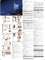
927000 - 927042
⌀8✕32
3✕
3✕
⌀8,4
1✕
927112
1✕ 2✕
4✕
6✕
6✕
4✕
M6✕12
⌀8✕32
⌀8,4
927122
2✕
4✕
4✕ 4✕ 4✕
_1
_1
_1
2✕
_2
8✕
_2
8✕
_2
2
1
3✕
⌀8✕32
⌀8,4
A
3✕
1
B
C
123
4✕
1
2
3
2✕
⌀8✕32
D
1
2
D
E
1
2
3
2✕
de GridLine Fußteil, Stützfuß, Knotenblech
1. Identifikationsdaten
Version 02 Originalbedienungsanleitung
Erstellungsdatum 07/2020
2. Allgemeine Hinweise
Bedienungsanleitung lesen, beachten, für späteres Nachschlagen auf-
bewahren und jederzeit verfügbar halten.
3. Sicherheit
3.1 BESTIMMUNGSGEMÄSSE VERWENDUNG
Nur an entsprechenden Bohrungen montieren.
3.1.1 Fußteil
Fußteil zur Montage an Arbeitsplatte der GridLine vario Werkbank.
Montage nur in Kombination mit Rückwand, Schubladengehäuse oder
Knotenbleche Nr. 927122.
Kabelkanäle im Fuß zum Verlegen von Kabelverbindungen.
3.1.2 Stützfuß
Stützfuß zur Montage an Eck-Arbeitsplatte.
Höhenverstellbar, um gerade Arbeitsfläche zu gewährleisten.
Montage nur in Kombination mit Rückwand oder zwei Knotenblechen
Nr. 927122.
Kabelkanäle im Fuß zum Verlegen von Kabeln.
3.1.3 Knotenblech
Knotenblech zur Montage an Arbeitsplatte und Fußteil der GridLine vario
Werkbank.
Zur Versteifung und Stabilisierung der Werkbank.
Doppeltes Knotenblech: Zur Verbindung zweier Arbeitsplatten. Für bündige
Ausrichtung zweier Arbeitsplatten zusätzliche Montage Koppelbeschlag Nr.
933585 empfohlen.
3.2 PERSÖNLICHE SCHUTZAUSRÜSTUNG
Nationale und regionale Vorschriften zur Sicherheit und Unfallverhütung beach-
ten. Schutzkleidung wie Fußschutz und Schutzhandschuhe müssen entsprechend
der bei der jeweiligen Tätigkeit zu erwartenden Risiken gewählt und bereitgestellt
werden.
4. Montagehinweise
i
Arbeitsplatte mit zwei Personen umdrehen und auf ebenen, sauberen
Untergrund legen.
4.1 FUSSTEIL
A
1. Jedes Fußteil mit drei Unterlegscheiben Ø8,4 und Holzschrauben Ø8×32 mit
Arbeitsplatte entsprechend Bohrungen verschrauben.
2. Bei Werkbänken ohne Gehäuse bodenstehend: Mit zweitem Fußteil wieder-
holen.
4.2 STÜTZFUSS
B
Stützfuß durch Ausstanzungen Kabelkanal mit zwei Holzschrauben Ø8×32 mit
Arbeitsplatte verschrauben.
4.2.1 Höhenverstellung anwenden
1. Zwei Schrauben mit Muttern an Fußende lösen.
2. Einschubmodul bis zur gewünschten Position schieben und festhalten.
» Bohrungen im Stützfuß müssen mit Bohrungen des Einschubmoduls
übereinstimmen.
3. Einschubmodul mit vorher entfernten Schrauben und Muttern mit Stützfuß
verschrauben.
4.3 KNOTENBLECH
4.3.1 Käfigmuttern einsetzen
C
i
Je Knotenblech am Kopfende des Fußes zwei Käfigmuttern in Ausstanzung
montieren.
1. Käfigmutter von vorne schräg in Ausstanzung einsetzen.
2. Mit Schraubendreher nach hinten schieben, festklipsen.
4.3.2 Einfaches Knotenblech montieren
D
Keine Montage notwendig bei Montage Rückwand.
1. Knotenblech mit zwei Sechskantschrauben M6×12 mit Käfigmuttern
verschrauben.
2. Knotenblech mit zwei Unterlegscheiben Ø8,4 und Holzschrauben Ø8×32
mit Arbeitsplatte verschrauben.
4.3.3 Doppeltes Knotenblech montieren
E
üFußteil an einer Arbeitsplatte montiert.
1. Knotenblech mit zwei Sechskantschrauben M6×12 mit Käfigmuttern
verschrauben.
2. Knotenblech mit je zwei Unterlegscheiben Ø8,4 und Holzschrauben Ø8×32
pro Arbeitsplatte verschrauben.
4.4 ELEKTROINSTALLATION
GEFAHR
Stromführende Komponenten
Lebensgefahr durch Stromschlag bei unsachgemäßer Montage
stromführender Komponenten.
» Elektroinstallation nur durch Elektrofachkraft.
» Notwendigkeit einer Schutzerdung prüfen.
» Vor Inbetriebnahme alle Komponenten auf Beschädigungen prüfen.
Kabel durch Ausstanzungen führen und im Fuß verlegen.
5. Technische Daten
5.1 FUSSTEIL
Artikelnummer* Größe Höhe Tiefe
927000,
927001
650 650 mm 700 mm
750 750 mm 700 mm
800 800 mm 700 mm
900 900 mm 700 mm
927004,
927006
800 650 mm 700 mm
900 750 mm 700 mm
950 800 mm 700 mm
1050 900 mm 700 mm
927040,
927042
800 800 mm 475 mm
900 900 mm 475 mm
*Zur Montage an Arbeitsplatte mit Tiefe 750 mm.
5.2 STÜTZFUSS
Artikelnummer Höhenverstellbereich Breite Tiefe
927112 1 750 – 1050 mm 70 mm 70 mm
5.3 BELASTUNGSMATRIX
i
Belastungsangaben für GridLine vario Werkbänke mit Plattenlänge 1000 – 2000
mm.
Kombinationsmöglichkeiten Flächenverteilte,
ruhende Last
1×Arbeitsplatte
2×Fußteile
4×Knotenbleche
1×Arbeitsplatte
2×Fußteile
1×Gehäuse hängend
2×Knotenbleche
400 kg
1×Arbeitsplatte
2×Fußteile
2×Rückwand einzeln
2×Knotenbleche
1×Arbeitsplatte
2×Fußteile
1×Gehäuse hängend
2×Rückwand einzeln
1×Knotenblech
600 kg
1×Arbeitsplatte
1×Fußteil
1×Gehäuse bodenstehend
2x Knotenbleche
800 kg
1×Arbeitsplatte
2×Gehäuse bodenstehend
1000 kg
en GridLine support leg, corner support leg,
stabilising plate
1. Identification data
Version 02 Translation of the original instruction
manual
Date created 07/2020
2. General instructions
Read the instructions for use, follow them and keep them available for
later reference.
3. Safety
3.1 INTENDED USE
Mount only on suitable holes.
3.1.1 Support leg
Support leg for installation on the worktop of the GridLine vario workbench.
Installation only in conjunction with a rear panel, drawer casing or stabilising
plates No. 927122.
Cable ducts in the leg for laying connecting cables.
3.1.2 Corner support leg
Corner support leg for installation on a corner worktop.
Height adjustable, to ensure a level working surface.
Installation only in conjunction with a rear panel or two stabilising plates No.
927122.
Cable ducts in the leg for laying cables.
3.1.3 Stabilising plate
Stabilising plate for installation on the worktop and support leg of the GridLine
vario workbench.
For stiffening and stabilising the workbench.
Double stabilising plate: For connecting two worktops. For flush alignment of
two worktops we recommend the additional installation of the joint strip No.
933585.
3.2 PERSONAL PROTECTIVE EQUIPMENT
Comply with the national and regional regulations for safety and accident preven-
tion. Protective work wear such as safety shoes and safety gloves appropriate for
the risks associated with the intended activities must be selected and provided.
4. Installation instructions
i
Two persons working together turn the worktop over and place it on a flat and
clean support surface.
4.1 SUPPORT LEG
A
1. Secure each support leg to the worktop using three Ø8.4 washers and Ø8×32
woodscrews, using the pre-drilled holes.
2. For workbenches without a casing standing on the floor: Repeat for the se-
cond support leg.
4.2 CORNER SUPPORT LEG
B
Secure the corner support leg to the worktop, inserting two Ø8×32 woods-
crews through the cable duct punched recesses.
4.2.1 Use height adjustment
1. Release two screws with nuts at the foot end.
2. Push the plug-in module into the desired position and secure it.
» The holes in the corner support leg must be in line with the holes in the
plug-in module.
3. Screw the plug-in module to the corner support leg, using the screws and
nuts previously removed.
4.3 STABILISING PLATE
4.3.1 Use cage nuts
C
i
For each stabilising plate install two cage nuts at the head end of the leg in the pun-
ched holes.
1. Insert the cage nuts obliquely from the front in the punched recess.
2. Use a screwdriver to push them back and clip them securely into position.
4.3.2 Installing a single stabilising plate
D
No installation is necessary for the rear panel.
1. Secure the stabilising plate using two M6×12 hex-head screws and cage nuts.
2. Secure each stabilising plate to the worktop using two Ø8.4 washers and
Ø8×32 woodscrews.
4.3.3 Installing a double stabilising plate
E
üThe support leg must be installed on the worktop.
1. Secure the stabilising plate using two M6×12 hex-head screws and cage nuts.
2. Secure each stabilising plate to the worktop using two Ø8.4 washers and
Ø8×32 woodscrews each.
4.4 ELECTRICAL INSTALLATION
DANGER
Electrically live components
Risk of death by electric shock if electrically live components are installed incor-
rectly.
» Electrical installation must be performed by an electrician.
» Check whether earthing is necessary.
» For commissioning, check all components for freedom from damage.
Pass cables through the punched apertures and within the leg.
5. Technical data
5.1 SUPPORT LEG
Article number* Size Height Depth
927000,
927001
650 650 mm 700 mm
750 750 mm 700 mm
800 800 mm 700 mm
900 900 mm 700 mm
927004,
927006
800 650 mm 700 mm
900 750 mm 700 mm
950 800 mm 700 mm
1050 900 mm 700 mm
927040,
927042
800 800 mm 475 mm
900 900 mm 475 mm
*For installation on a worktop of depth 750mm.
5.2 CORNER SUPPORT LEG
Article number Height adjustment ran-
ge
Width Depth
927112 1 750 – 1050 mm 70 mm 70 mm
5.3 LOADING MATRIX
i
Loading data for GridLine vario workbenches with worktop length 1000 –
2000mm.
Available combinations Distributed non-dynamic
load
1×worktop
2×support legs
4×stabilising plates
1×worktop
2×support legs
1×suspended casing
2×stabilising plates
400 kg
1×worktop
2×support legs
2×rear panels
2×stabilising plates
1×worktop
2×support legs
1×suspended casing
2×individual rear pa-
nels
1×stabilising plate
600 kg
1×worktop
1×support leg
1×casing standing on the
floor
2×stabilising plates
800 kg
1×worktop
2×casings standing on the
floor
1000 kg
es Pie soporte, pie de soporte, chapa de nudos
GridLine
1. Datos de identificación
Versión 02 Traducción del manual de instruccio-
nes original
Fecha de creación 07/2020
2. Indicaciones generales
Lea, observe y conserve el manual de instrucciones de uso para consul-
tas posteriores, y téngalo siempre a mano.
3. Seguridad
3.1 USO CONFORME A LO PREVISTO
Montar solo en las perforaciones correspondientes.
3.1.1 Pie soporte
Pie soporte para el montaje en tablero de trabajo del banco de trabajo GridLi-
ne vario.
Montaje solo en combinación con panel posterior, carcasa de cajones o chapas
de nudos n.º927122.
Canales para cable en el pie para la colocación de conexiones de cables.
3.1.2 Pie de soporte
Pie de soporte para el montaje en tablero de esquina.
Regulable en altura, para asegurar una superficie de trabajo recta.
Montaje solo en combinación con panel posterior o dos chapas de nudos
n.º927122.
Canales para cable en el pie para la colocación de cables.
3.1.3 Chapa de nudos
Chapa de nudos para el montaje en tablero de trabajo y pie soporte del banco
de trabajo GridLine vario.
Para reforzar y estabilizar el banco de trabajo.
Chapa de nudos doble: Para la conexión de dos tableros de trabajo. Para la ali-
neación enrasada de dos tableros de trabajo se recomienda el montaje adicio-
nal del nudo de unión n.º933585.
3.2 EQUIPO DE PROTECCIÓN INDIVIDUAL
Tener en cuenta las normas nacionales y regionales en cuanto a seguridad y pre-
vención de accidentes. La ropa de protección como protección para los pies y
guantes protectores se han de seleccionar y disponer de acuerdo con los riesgos
propios de la actividad correspondiente.
4. Indicaciones para el montaje
i
Dar la vuelta al tablero de trabajo por medio de dos personas y colocarlo sobre
un fondo plano y limpio.
4.1 PIE SOPORTE
A
1. Atornillar cada pie soporte con tres arandelas de Ø8,4 y tornillos para madera
de Ø8×32 al tablero de trabajo de acuerdo las perforaciones.
2. En bancos de trabajo sin carcasa apoyada en el suelo: Repetir la operación con
el segundo pie soporte.
4.2 PIE DE SOPORTE
B
Atornillar el pie de soporte al tablero de trabajo por los recortes del canal para
cables con dos tornillos para madera Ø8×32.
4.2.1 Aplicar la regulación de la altura
1. Soltar los dos tornillos con tuercas en el extremo del pie.
2. Deslizar el módulo insertado hasta la posición deseada y sujetarlo.
» Las perforaciones del pie de soporte han de coincidir con las del módu-
lo insertado.
3. Atornillar el módulo insertado al pie de soporte con los tornillos y las tuercas
que se retiraron anteriormente.
4.3 CHAPA DE NUDOS
4.3.1 Colocar las tuercas de jaula
C
i
Montar dos tuercas de jaula en el recorte del lado en cada chapa de nudos del ex-
tremo superior del pie.
1. Inserte la tuerca enjaulada diagonalmente desde el frente en el corte.
2. Empujarla hacia atrás con un destornillador y engancharla.
4.3.2 Montar la chapa de nudos sencilla
D
No es necesario el montaje en el caso de panel posterior montado.
1. Atornillar la chapa de nudos con dos tornillos de cabeza hexagonal M6×12 y
tuercas de jaula.
2. Atornillar la chapa de nudos con dos arandelas de Ø8,4 y tornillos para made-
ra de Ø8×32 al tablero de trabajo.
4.3.3 Montar la chapa de nudos doble
E
üPie soporte montado en un tablero de trabajo.
1. Atornillar la chapa de nudos con dos tornillos de cabeza hexagonal M6×12 y
tuercas de jaula.
2. Atornillar la chapa de nudos con dos arandelas Ø8,4 y tornillos para madera
Ø8×32 por cada tablero de trabajo.
4.4 INSTALACIÓN ELÉCTRICA
PELIGRO
Componentes conductores de la corriente
Peligro de muerte por electrocución en caso de montaje inadecuado de compo-
nentes conductores de la corriente.
» La instalación eléctrica solo puede realizarla personal cualificado para trabajos
electrotécnicos.
» Comprobar la necesidad de protección por una toma de tierra.
» Examinar todos los componentes antes de la puesta en marcha para compro-
bar que no estén dañados.
Pasar los cables por los recortes y colocarlos en el pie.
5. Especificaciones técnicas
5.1 PIE SOPORTE
Número de artícu-
lo*
Tamaño Altura Profundidad
927000,
927001
650 650mm 700mm
750 750mm 700mm
800 800mm 700mm
900 900mm 700mm
927004,
927006
800 650mm 700mm
900 750mm 700mm
950 800mm 700mm
1050 900mm 700mm
927040,
927042
800 800mm 475mm
900 900mm 475mm
*Para el montaje en tablero de trabajo de 750mm de profundidad.
5.2 PIE DE SOPORTE
Número de artícu-
lo
Intervalo de regulación
de altura
Anchura Profundidad
927112 1 750-1050mm 70mm 70mm
5.3 MATRIZ DE CARGA
i
Datos de carga para bancos de trabajo GridLine vario con longitud de tablero
1000-2000mm.

Posibilidades de combinación Caga distribuida en la super-
ficie, en reposo
1 tablero de trabajo
2 pies soporte
4 chapas de nudos
1 tablero de trabajo
2 pies soporte
1 carcasa suspendida
2 chapas de nudos
400kg
1 tablero de trabajo
2 pies soporte
2 paneles posteriores indi-
viduales
2 chapas de nudos
1 tablero de trabajo
2 pies soporte
1 carcasa suspendida
2 paneles posteriores
1 chapa de nudos
600kg
1 tablero de trabajo
1 pie soporte
1 carcasa apoyada en el
suelo
2 chapas de nudos
800kg
1 tablero de trabajo
2 carcasas apoyadas en el
suelo
1000kg
fr Piètement, pied d'appui, gousset GridLine
1. Données d'identification
Version 02 Traduction du manuel d'instructions
original
Date de création 07/2020
2. Remarques générales
Lisez, respectez et conservez le mode d'emploi à des fins de consultati-
on ultérieure, et gardez-le toujours à disposition.
3. Sécurité
3.1 UTILISATION NORMALE
Monter uniquement sur les trous correspondants.
3.1.1 Piètement
Piètement pour montage sur un plan de travail d'un établi GridLine vario.
Montage uniquement en combinaison avec une paroi arrière, un caisson de ti-
roirs ou des goussets 927122.
Conduites de câbles dans le pied pour la pose de câbles.
3.1.2 Pied d'appui
Pied d'appui pour montage sur un plan de travail d'angle.
Réglable en hauteur afin de garantir une surface de travail plane.
Montage uniquement en combinaison avec une paroi arrière ou deux goussets
927122.
Conduites de câbles dans le pied pour la pose de câbles.
3.1.3 Gousset
Gousset pour montage sur un plan de travail et un piètement d'un établi Grid-
Line vario.
Pour rigidification et stabilisation de l'établi.
Gousset double: pour relier deux plans de travail. Pour un alignement précis
de deux plans de travail, le montage supplémentaire d'un couplage 933585 est
recommandé.
3.2 EQUIPEMENT DE PROTECTION INDIVIDUELLE
Respecter les réglementations nationales et régionales en matière de sécurité et
de prévention des accidents. Les vêtements de protection, tels que les chaussures
et les gants, doivent être choisis et mis à disposition en fonction des risques
prévus pendant l'activité concernée.
4. Consignes de montage
i
Retourner le plan de travail avec l'aide de deux personnes et le poser sur une
surface plane et propre.
4.1 PIÈTEMENT
A
1. Visser chaque piètement au plan de travail à l'aide de trois rondelles Ø8,4 et
de vis à bois Ø8×32 selon les trous correspondants.
2. Pour les établis sans caisson au sol: répéter la procédure avec le deuxième
piètement.
4.2 PIED D'APPUI
B
Visser le pied d'appui au plan de travail par les découpes de la conduite de
câbles à l'aide de deux vis à bois Ø8×32.
4.2.1 Utilisation du réglage en hauteur
1. Desserrer deux vis avec écrous au bas du pied.
2. Pousser le module à insérer jusqu'à la position désirée et le fixer.
» Les trous dans le pied d'appui doivent correspondre à ceux du module à
insérer.
3. Visser le module à insérer au pied d'appui à l'aide des vis et écrous ôtés précé-
demment.
4.3 GOUSSET
4.3.1 Mise en place des écrous cage
C
i
Monter deux écrous cage dans la découpe latérale par gousset en haut du pied.
1. Insérez l'écrou cage en diagonale dans la découpe avant.
2. Pousser vers l'arrière à l'aide d'un tournevis, clipser fermement.
4.3.2 Montage d'un gousset simple
D
Aucun montage nécessaire en cas de montage d'une paroi arrière.
1. Visser le gousset aux écrous cage à l'aide de deux vis à 6 pans M6×12.
2. Visser le gousset au plan de travail à l'aide de deux rondelles Ø8,4 et de vis à
bois Ø8×32.
4.3.3 Montage d'un gousset double
E
üPiètement monté à un plan de travail.
1. Visser le gousset aux écrous cage à l'aide de deux vis à 6 pans M6×12.
2. Visser le gousset à chaque plan de travail à l'aide de deux rondelles Ø8,4 et de
vis à bois Ø8×32.
4.4 INSTALLATION ÉLECTRIQUE
DANGER
Composants conducteurs
Danger de mort par choc électrique en cas de montage incorrect de composants
conducteurs.
» Installation électrique uniquement par un électricien qualifié.
» Vérifier la nécessité d'une terre de protection.
» Avant la mise en service, vérifier que tous les composants ne sont pas endom-
magés.
Acheminer les câbles par les découpes et les poser dans le pied.
5. Caractéristiques techniques
5.1 PIÈTEMENT
Code article* Réf. Hauteur Profondeur
927000,
927001
650 650mm 700mm
750 750mm 700mm
800 800mm 700mm
900 900mm 700mm
927004,
927006
800 650mm 700mm
900 750mm 700mm
950 800mm 700mm
1050 900mm 700mm
927040,
927042
800 800mm 475mm
900 900mm 475mm
*Pour montage sur un plan de travail de 750mm de profondeur.
5.2 PIED D'APPUI
Code article Plage de réglage en
hauteur
Largeur Profondeur
927112 1 750 – 1050mm 70mm 70mm
5.3 TABLEAU DES CHARGES
i
Indications de charge pour les établis GridLine vario avec longueur de plan de
travail de 1000 – 2000mm.
Possibilités de combinaisons Charge statique, uniformé-
ment répartie
1×plan de travail
2×piètements
4×goussets
1×plan de travail
2×piètements
1×caisson suspendu
2×goussets
400kg
1×plan de travail
2×piètements
2×parois arrière individu-
elles
2×goussets
1×plan de travail
2×piètements
1×caisson suspendu
2×parois arrière indi-
viduelles
1×gousset
600kg
1×plan de travail
1×piètement
1×caisson au sol
2×goussets
800kg
1×plan de travail
2×caissons au sol
1000kg
it Strutture portanti, piedino di appoggio e
raccordo a gomito GridLine
1. Dati identificativi
Versione 02 Traduzione del manuale di istruzioni
originale
Data di creazione 07/2020
2. Note generali
Leggere il manuale d’uso, rispettarlo, conservarlo per riferimento futuro
e tenerlo sempre a portata di mano.
3. Sicurezza
3.1 USO PREVISTO
Montare solo nei fori corrispondenti.
3.1.1 Strutture portanti
Strutture portanti da montare al piano di lavoro del banco da lavoro GridLine
vario.
Montaggio solo in combinazione con parete posteriore, corpo per cassetti o
raccordi a gomito n. art. 927122.
Canaline per cavi integrate nella base per la posa dei cavi di collegamento.
3.1.2 Piedino di appoggio
Piedino di appoggio da montare al piano di lavoro angolare.
Con altezza regolabile per garantire una superficie di lavoro diritta.
Montaggio solo in combinazione con parete posteriore o due raccordi a gomi-
to n. art. 927122.
Canaline per cavi integrate nella base per la posa dei cavi.
3.1.3 Raccordo a gomito
Raccordo a gomito da montare al piano di lavoro e alle strutture portanti del
banco da lavoro GridLine vario.
Per garantire una maggiore solidità e stabilità del banco da lavoro.
Raccordo a gomito doppio: per unire due piani di lavoro. Per allineare due pia-
ni di lavoro, si consiglia di montare anche una borchia di accoppiamento n. art.
933585.
3.2 DISPOSITIVI DI PROTEZIONE ANTINFORTUNISTICI
Osservare le norme nazionali e regionali in materia di sicurezza e prevenzione
degli infortuni. L’abbigliamento di protezione, come scarpe di sicurezza e guanti
protettivi, deve essere selezionato e messo a disposizione conformemente ai ri-
schi legati alla rispettiva attività.
4. Indicazioni di montaggio
i
Capovolgere il piano di lavoro con l’aiuto di due persone e appoggiarlo su una
superficie piana e pulita.
4.1 STRUTTURE PORTANTI
A
1. Avvitare ogni struttura portante al piano di lavoro in base alla disposizione dei
fori usando tre rondelle di Ø 8,4 e tre viti in legno di Ø 8×32.
2. Nei banchi da lavoro senza corpo poggiato a terra: ripetere l’operazione con
una seconda struttura portante.
4.2 PIEDINO DI APPOGGIO
B
Avvitare il piedino di appoggio al piano di lavoro attraverso le punzonature
della canalina per cavi usando due viti in legno di Ø 8×32.
4.2.1 Applicazione del meccanismo di regolazione dell’altezza
1. Svitare le due viti con i dadi posti all’estremità della base.
2. Spingere il modulo da innesto fino alla posizione desiderata e fissarlo.
» I fori del piedino di appoggio devono combaciare con i fori del modulo
da innesto.
3. Avvitare il modulo da innesto al piedino di appoggio usando i dadi e le viti
precedentemente tolti.
4.3 RACCORDO A GOMITO
4.3.1 Inserimento dei dadi in gabbia
C
i
Per ciascun raccordo a gomito, montare due dadi in gabbia nella punzonatura la-
terale situata nell’estremità superiore della base.
1. Inserire il dado a gabbia in diagonale nell'intaglio frontale.
2. Spingerlo all’indietro con l’aiuto di un giravite e fissarlo mediante le clip di ag-
gancio.
4.3.2 Montaggio di un raccordo a gomito semplice
D
Nessun montaggio necessario in caso di montaggio di una parete posteriore.
1. Avvitare il raccordo a gomito ai dadi in gabbia usando due viti esagonali
M6×12.
2. Avvitare il raccordo a gomito al piano di lavoro usando due rondelle di Ø 8,4 e
due viti in legno di Ø 8×32.
4.3.3 Montaggio di un raccordo a gomito doppio
E
üLe strutture portanti sono montate al piano di lavoro.
1. Avvitare il raccordo a gomito ai dadi in gabbia usando due viti esagonali
M6×12.
2. Avvitare il raccordo a gomito a ogni piano di lavoro usando due rondelle di Ø
8,4 e due viti in legno di Ø 8×32 ciascuno.
4.4 INSTALLAZIONE DI COMPONENTI ELETTRICI
PERICOLO
Componenti sotto tensione
Pericolo di morte per scosse elettriche in caso di componenti sotto tensione mon-
tati in maniera errata.
» L’installazione dei componenti elettrici deve essere effettuata solo da elettricisti
qualificati.
» Verificare la necessità di una messa a terra di protezione.
» Prima della messa in funzione, controllare che i componenti non siano danneg-
giati.
Far passare i cavi attraverso i fori e posarli nella base.
5. Dati tecnici
5.1 STRUTTURE PORTANTI
N. art.* Dim. Altezza Profondità
927000,
927001
650 650 mm 700 mm
750 750 mm 700 mm
800 800 mm 700 mm
900 900 mm 700 mm
927004,
927006
800 650 mm 700 mm
900 750 mm 700 mm
950 800 mm 700 mm
1.050 900 mm 700 mm
927040,
927042
800 800 mm 475 mm
900 900 mm 475 mm
*Per il montaggio al piano di lavoro con profondità di 750 mm.
5.2 PIEDINO DI APPOGGIO
Numero articolo Campo di regolazione
dell’altezza
Larghezza Profondità
927112 1 750 – 1050 mm 70 mm 70 mm
5.3 MATRICE DI CARICO
i
Indicazioni relative al carico per i banchi da lavoro GridLine vario con lunghezza
del piano compresa tra 1.000 e 2.000 mm.
Possibili combinazioni Carico statico ripartito su tut-
ta la superficie
1× piano di lavoro
2× strutture portanti
4× raccordi a gomito
1× piano di lavoro
2× strutture portanti
1× alloggiamento ap-
peso
2× raccordi a gomito
400 kg
1× piano di lavoro
2× strutture portanti
2× pareti posteriori singo-
le
2× raccordi a gomito
1× piano di lavoro
2× strutture portanti
1× alloggiamento ap-
peso
2× pareti posteriori
singole
1× raccordo a gomito
600 kg
1× piano di lavoro
1× struttura portante
1× corpo poggiato a terra
2× raccordi a gomito
800 kg
1× piano di lavoro
2× corpi poggiati a terra
1.000 kg
pl GridLine segment nóg, podpora, węzłówka
1. Dane identyfikacyjne
Wersja 02 Tłumaczenie oryginalnej instrukcji
obsługi
Data opracowania 07/2020
2. Informacje ogólne
Należy zapoznać się z instrukcją obsługi i przestrzegać jej oraz zacho-
wać ją na przyszłość, przechowując w dostępnym miejscu.
3. Bezpieczeństwo
3.1 UŻYTKOWANIE ZGODNIE ZPRZEZNACZENIEM
Montować wyłącznie we właściwych otworach.
3.1.1 Segment nóg
Segment nóg montowany na blatach roboczych stołów warsztatowych GridLi-
ne vario.
Montaż tylko w połączeniu ze ścianą tylną, obudową szuflad lub węzłówkami
nr 927122.
Kanały kablowe w nodze umożliwiają ułożenie połączeń kablowych.
3.1.2 Podpora
Podpora do montażu w blacie kątowym.
Z regulacją wysokości zapewniającą płaską powierzchnię roboczą.
Montaż tylko w połączeniu ze ścianą tylną lub dwoma węzłówkami nr 927122.
Kanały kablowe w nodze umożliwiające ułożenie przewodów.
3.1.3 Węzłówka
Węzłówka montowana na blatach roboczych i segmentach nóg stołów warsz-
tatowych GridLine vario.
Usztywnia i stabilizuje stół warsztatowy.
Węzłówka podwójna: Do łączenia dwóch blatów roboczych. W celu równego
ułożenia dwóch blatów roboczych zaleca się dodatkowo montaż złączki do łąc-
zenia blatów nr 933585.
3.2 ŚRODKI OCHRONY INDYWIDUALNEJ
Przestrzegać krajowych iregionalnych przepisów dotyczących bezpieczeństwa
izapobiegania nieszczęśliwym wypadkom. Należy dobrać iudostępnić odzież
ochronną, taką jak ochrona stóp irękawice ochronne, odpowiednio do rodzajów
ryzyka oczekiwanego podczas wykonywania danej czynności.
4. Wskazówki dotyczące montażu
i
Dwie osoby muszą obrócić blat roboczy i ułożyć go na równym i czystym po-
dłożu.
4.1 SEGMENT NÓG
A
1. Każdy segment nóg przykręcić do blatu roboczego zgodnie z otworami korzy-
stając z trzech podkładek Ø8,4 i wkrętów do drewna Ø8×32.
2. W przypadku stołów roboczych bez obudowy stojącej: Powtórzyć czynności z
drugim segmentem nóg.
4.2 PODPORA
B
Przez wycięcia w kanale kablowym przykręcić podporę do blatu roboczego
korzystając z dwóch wkrętów do drewna Ø8×32.
4.2.1 Regulacja wysokości
1. Odkręcić dwie śruby wraz z nakrętkami na krańcu nogi.
2. Przesunąć moduł wsuwany w wybrane położenie i zamocować.
» Otwory w podporze muszą odpowiadać otworom modułu wsuwanego.
3. Przykręcić moduł wsuwany do podpory korzystając z uprzednio usuniętych
śrub i nakrętek.
4.3 WĘZŁÓWKA
4.3.1 Nakładanie nakrętek klatkowych
C
i
Dla każdej węzłówki zamontować dwie nakrętki klatkowe w wycięciu z boku na
krańcu nogi.
1. Włóż nakrętkę koszyczkową po przekątnej od przodu do wycięcia.
2. Korzystając z wkrętaka przesunąć do tyłu i zatrzasnąć.
4.3.2 Montaż węzłówki pojedynczej
D
Montaż niewymagany w razie instalacji ściany tylnej.
1. Przykręcić węzłówkę do nakrętek klatkowych korzystając z dwóch śrub z łbem
sześciokątnym M6×12.
2. Węzłówkę przykręcić do blatu roboczego używając dwóch podkładek Ø8,4 i
wkrętów do drewna Ø8×32.
4.3.3 Montaż węzłówki podwójnej
E
üSegment nóg mocowany na blacie roboczym.
1. Przykręcić węzłówkę do nakrętek klatkowych korzystając z dwóch śrub z łbem
sześciokątnym M6×12.
2. Węzłówkę przykręcić do blatu roboczego używając dwóch podkładek Ø8,4 i
wkrętów do drewna Ø8×32.
4.4 INSTALACJA ELEKTRYCZNA
NIEBEZPIECZEŃSTWO
Komponenty przewodzące prąd
Ryzyko śmiertelnego porażenia prądem wskutek nieprawidłowego montażu ele-
mentów przewodzących prąd.
» Wykonywaniem instalacji elektrycznej mogą zajmować się wyłącznie wykwalifi-
kowani elektrycy.
» Konieczność sprawdzenia uziemienia ochronnego.
» Przed uruchomieniem sprawdzić wszystkie komponenty pod kątem uszkodze-
nia.
Poprowadzić przewód przez wycięcia i ułożyć w nodze.
5. Dane techniczne
5.1 SEGMENT NÓG
Numer artykułu* Rozmiar Wysokość Głębokość
927000,
927001
650 650 mm 700 mm
750 750 mm 700 mm
800 800 mm 700 mm
900 900 mm 700 mm
927004,
927006
800 650 mm 700 mm
900 750 mm 700 mm
950 800 mm 700 mm
1050 900 mm 700 mm
927040,
927042
800 800 mm 475 mm
900 900 mm 475 mm
*Do montażu na blatach roboczych o głębokości 750 mm.
5.2 PODPORA
Numer artykułu Zakres regulacji wyso-
kości
Szerokość Głębokość
927112 1 750–1050mm 70 mm 70 mm
5.3 ZESTAWIENIE OBCIĄŻEŃ
i
Wartości obciążeń dla stołów warsztatowych GridLine vario o długości blatu
1000–2000 mm.
Możliwe kombinacje Obciążenie statyczne, po-
wierzchniowe
1×blat roboczy
2×segment nóg
4×węzłówka
1×blat roboczy
2×segment nóg
1×obudowa wisząca
2×węzłówka
400 kg
1×blat roboczy
2×segment nóg
2לcianka tylna pojedyn-
cza
2×węzłówka
1×blat roboczy
2×segment nóg
1×obudowa wisząca
2לcianka tylna poje-
dyncza
1×węzłówka
600 kg
1×blat roboczy
1×segment nóg
1×obudowa wisząca
2x węzłówka
800 kg
1×blat roboczy
2×obudowa stojąca
1000 kg
-
 1
1
-
 2
2


Garant GridLine support leg Instrukcja obsługi
- Typ
- Instrukcja obsługi
w innych językach
Powiązane artykuły
Inne dokumenty
-
Beta 3910 Instrukcja obsługi
-
Festool MFT/3 Instrukcja obsługi
-
Scheppach 73190912 Translation From Original Manual
-
Groupe Brandt SP-350 Instrukcja obsługi
-
Gaggenau AA 490 Instrukcja instalacji
-
Bosch PPS816M91E Instrukcja obsługi
-
Bosch EP816SB21E/01 Instrukcja obsługi
-
-
Hotpoint Ariston TQ 640K GH/HA instrukcja
-
Whirlpool TQ 751 (BK) K X /HA instrukcja