Indesit KN3T760SA(W)/U instrukcja
- Kategoria
- Mikrofale
- Typ
- instrukcja

GB
COOKER AND OVEN
KN3T760SA/U
Contents
Installation, 2-5
Positioning and levelling
Electrical connection
Gas connection
Adapting to different types of gas
Table of burner and nozzle specifications
Table of characteristics
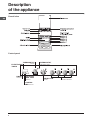
Description of the appliance, 6
Overall view
Control panel
Start-up and use, 7-11
Using the hob
Using the oven
Cooking modes
Practical cooking advice
Electronic timer
Planning cooking with the electronic programmer
Oven cooking advice table
Precautions and tips, 12
General safety
Disposal
Respecting and conserving the environment
Care and maintenance, 13
Switching the appliance off
Cleaning the appliance
Replacing the oven light bulb
Gas tap maintenance
Assistance
Operating Instructions
English, 1
GB
Polski, 14
PL
Eesti keeles,54
LV
LT
Latviešu,41
Lietuviu;28
ET

2
GB
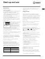
! Before operating your new appliance please read this
instruction booklet carefully. It contains important
information concerning the safe installation and
operation of the appliance.
! Please keep these operating instructions for future
reference. Make sure that the instructions are kept with
the appliance if it is sold, given away or moved.
! The appliance must be installed by a qualified
professional according to the instructions provided.
! Any necessary adjustment or maintenance must be
performed after the cooker has been disconnected
from the electricity supply.
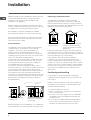
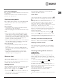
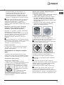
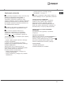
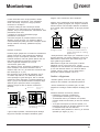
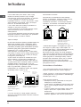
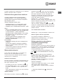
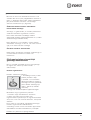
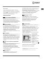
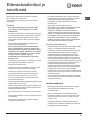
Room ventilation
The appliance may only be installed in permanently-
ventilated rooms, according to current national
legislation. The room in which the appliance is
installed must be ventilated adequately so as to
provide as much air as is needed by the normal gas
combustion process (the flow of air must not be lower
than 2 m
3
/h per kW of installed power).
The air inlets, protected by grilles, should have a duct
with an inner cross section of at least 100 cm
2
and
should be positioned so that they are not liable to
even partial obstruction (
see figure A
).
These inlets should be enlarged by 100% - with a
minimum of 200 cm
2
- whenever the surface of the hob
is not equipped with a flame failure safety device.
When the flow of air is provided in an indirect manner
from adjacent rooms (
see figure B
), provided that
these are not communal parts of a building, areas with
increased fire hazards or bedrooms, the inlets should
be fitted with a ventilation duct leading outside as
described above.
! After prolonged use of the appliance, it is advisable to
open a window or increase the speed of any fans used.
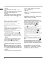
Disposing of combustion fumes
The disposal of combustion fumes should be
guaranteed using a hood connected to a safe and
efficient natural suction chimney, or using an electric
fan that begins to operate automatically every time the
appliance is switched on (
see figure
).
! The liquefied petroleum gases are heavier than air
and collect by the floor, therefore all rooms containing
LPG cylinders must have openings leading outside so
that any leaked gas can escape easily.
LPG cylinders, therefore, whether partially or
completely full, must not be installed or stored in
rooms or storage areas that are below ground level
(cellars, etc.). Only the cylinder being used should be
stored in the room; this should also be kept well away
from sources of heat (ovens, chimneys, stoves) that
may cause the temperature of the cylinder to rise
above 50°C.
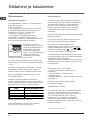
Positioning and levelling
! It is possible to install the appliance alongside
cupboards whose height does not exceed that of the
hob surface.
! Make sure that the wall in contact with the back of
the appliance is made from a non-flammable, heat-
resistant material (T 90°C).
To install the appliance correctly:
• Place it in the kitchen, dining room or the bed-sit
(not in the bathroom).
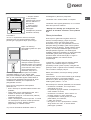
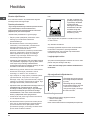
• If the top of the hob is higher than the cupboards,
the appliance must be installed at least 200 mm
away from them.
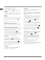
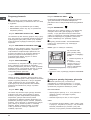
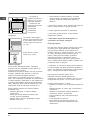
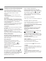
• If the cooker is installed underneath a wall cabinet,
there must be a minimum distance of 420 mm
between this cabinet and the top of the hob.
Installation
Adjacent room Room requiring
ventilation
A
B
Ventilation opening for
comburent air
Increase in the gap
between the door and
the flooring
A
Fumes channelled
straight outside
Fumes channelled through a
chimney or a branched flue
system (reserved for cooking
appliances)

GB
3
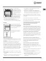
• If the cooker is
installed underneath a
wall cabinet, there must
be a minimum distance
of 420 mm between this
cabinet and the top of
the hob.
This distance should be
increased to 700 mm if
the wall cabinets are
flammable (
see figure
).
• Do not position blinds behind the cooker or less
than 200 mm away from its sides.
• Any hoods must be installed according to the
instructions listed in the relevant operating manual.
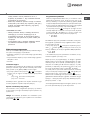
Levelling
If it is necessary to level the
appliance, screw the adjustable
feet into the places provided on
each corner of the base of the
cooker (
see figure
).
The legs* fit into the slots on
the underside of the base of
the cooker.
Electrical connection
Install a standardised plug corresponding to the load
indicated on the appliance data plate (
see Technical
data table
).
The appliance must be directly connected to the
mains using an omnipolar circuit-breaker with a
minimum contact opening of 3 mm installed between
the appliance and the mains. The circuit-breaker must
be suitable for the charge indicated and must comply
with NFC 15-100 regulations (the earthing wire must
not be interrupted by the circuit-breaker). The supply
cable must be positioned so that it does not come into
contact with temperatures higher than 50°C at any
point.
Before connecting the appliance to the power supply,
make sure that:
• The appliance is earthed and the plug is compliant with
the law.
• The socket can withstand the maximum power of the
appliance, which is indicated by the data plate.
HOOD
420
Min.
min. 650 mm. with hood
min.
700 mm. without hood
mm.
600
Min. mm.
420
Min. mm.
• The voltage is in the range between the values
indicated on the data plate.
• The socket is compatible with the plug of the
appliance. If the socket is incompatible with the
plug, ask an authorised technician to replace it. Do
not use extension cords or multiple sockets.
! Once the appliance has been installed, the power
supply cable and the electrical socket must be easily
accessible.
! The cable must not be bent or compressed.
! The cable must be checked regularly and replaced
by authorised technicians only.
! The manufacturer declines any liability should
these safety measures not be observed.
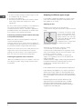
Gas connection
Connection to the gas network or to the gas cylinder
may be carried out using a flexible rubber or steel hose,
in accordance with current national legislation and after
making sure that the appliance is suited to the type of
gas with which it will be supplied (see the rating sticker
on the cover: if this is not the case
see below
). When
using liquid gas from a cylinder, install a pressure
regulator which complies with current national
regulations. To make connection easier, the gas supply
may be turned sideways*: reverse the position of the
hose holder with that of the cap and replace the gasket
that is supplied with the appliance.
! Check that the pressure of the gas supply is
consistent with the values indicated in the Table of
burner and nozzle specifications (
see below
). This will
ensure the safe operation and durability of your
appliance while maintaining efficient energy
consumption.
Gas connection using a flexible rubber hose
Make sure that the hose complies with current
national legislation. The internal diameter of the hose
must measure: 8 mm for liquid gas supply; 13 mm for
methane gas supply.
Once the connection has been performed, make sure
that the hose:
• Does not come into contact with any parts that
reach temperatures of over 50°C.
• Is not subject to any pulling or twisting forces and
that it is not kinked or bent.
• Does not come into contact with blades, sharp
corners or moving parts and that it is not
compressed.

4
GB
• Is easy to inspect along its whole length so that
its condition may be checked.
• Is shorter than 1500 mm.
• Fits firmly into place at both ends, where it will be
fixed using clamps that comply with current
regulations.
! If one or more of these conditions is not fulfilled or if
the cooker must be installed according to the
conditions listed for class 2 - subclass 1 appliances
(installed between two cupboards), the flexible steel
hose must be used instead (
see below
).
Connecting a flexible jointless stainless steel pipe
to a threaded attachment
Make sure that the hose and gaskets comply with
current national legislation.
To begin using the hose, remove the hose holder on
the appliance (the gas supply inlet on the appliance is
a cylindrical threaded 1/2 gas male attachment).
! Perform the connection in such a way that the hose
length does not exceed a maximum of 2 metres,
making sure that the hose is not compressed and
does not come into contact with moving parts.
Checking the tightness of the connection
When the installation process is complete, check the
hose fittings for leaks using a soapy solution. Never
use a flame.
Adapting to different types of gas
It is possible to adapt the appliance to a type of gas
other than the default type (this is indicated on the
rating label on the cover).
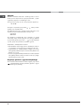
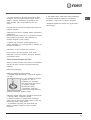
Adapting the hob
Replacing the nozzles for the hob burners:
1. Remove the hob grids and slide the burners off their
seats.
2. Unscrew the nozzles using
a 7 mm socket spanner (
see
figure
), and replace them with
nozzles suited to the new type
of gas (
see Burner and nozzle
specifications table
).
3. Replace all the components
by following the above
instructions in reverse.
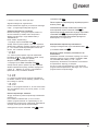
Adjusting the hob burners’ minimum setting:
1. Turn the tap to the minimum position.
2. Remove the knob and adjust the regulatory screw,
which is positioned inside or next to the tap pin, until
the flame is small but steady.
! If the appliance is connected to a liquid gas
supply, the regulatory screw must be fastened as
tightly as possible.
3. While the burner is alight, quickly change the position of
the knob from minimum to maximum and vice versa
several times, checking that the flame is not
extinguished.
! The hob burners do not require primary air adjustment.
! After adjusting the appliance so it may be used with a
different type of gas, replace the old rating label with a
new one that corresponds to the new type of gas (these
labels are available from Authorised Technical Assistance
Centres).
! Should the gas pressure used be different (or vary
slightly) from the recommended pressure, a suitable
pressure regulator must be fitted to the inlet hose in
accordance with current national regulations relating to
“regulators for channelled gas”.

GB
5
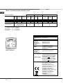
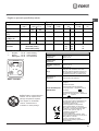
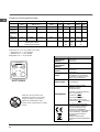
TABLE OF CHARACTERISTSICS
Dimensions (with
drawn guide rails)
width 39 cm
height 34 cm
depth 41 cm
Volume (with
drawn guide rails)
54 l
Dimensions of the
lower compartment
width 42 cm
height 23 cm
depth 44 cm
Burners
may be adapted for use with any type
of gas shown on the data plate, which
is located inside the flap or, after the
oven compartment has been opened,
on the left-hand wall inside the oven.
Voltage and
frequency
see data plate
ENERGY LABEL
Directive 2002/40/EC on the label of
electric ovens.
Standard EN 50304
Energy consumption for Natural
convection – heating mode:
Convection;
Declared energy consumption for
Forced convection Class – heating
mode: Baking
This appliance conforms to the
following European Economic
Community directives: 2006/95/EC
dated 12/12/06 (Low Voltage) and
subsequent amendments -
2004/108/EC dated 15/12/04
(Electromagnetic Compatibility) and
subsequent amendments - 93/68/EEC
dated 22/07/93 and subsequent
amendments.
2002/96/EC
2009/142 of 30/11/09 (Gas)
1275/2008 (Stand-by/ Off mode)
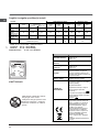
WARNING! The glass lid can break in if
it is heated up. Turn off all the burners
and the electric plates before closing
the lid. *Applies to the models with glass
cover only.
KN3T760SA/U
S
S
TC
A
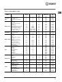
Table of burner and nozzle specifications
Table 1 Liquid Gas Natural Gas
!!
"
#
!!
"
$%%
&&
' '( ) (' * +'( +'+ '' '*
,"
-%,
.) * / ' . '0 '( / 0
12
,1
) / ' )+ .' . .( *)
,
3
-3
-23
+0'
+
')
'.
+)
/)
+
.
+)
At 15°C and 1013 mbar- dry gas
** Propane P.C.S. = 50,37 MJ/Kg
*** Butane P.C.S. = 49,47 MJ/Kg
Natural P.C.S. = 37,78 MJ/m
3

6
GB
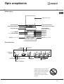
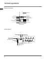
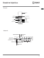
Description
of the appliance
Overall view
Control panel
THERMOSTAT
THERMOSTAT
indicator light
Hob BURNER
control knobs
SELECTOR
ELECTRONIC
TIMER
knob
knob
TIMER
button
COOKING
END TIME
button
COOKING
TIME button

GB
7
Start-up and use
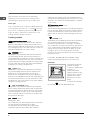
Using the hob
Lighting the burners
For each BURNER knob there is a full ring showing
the strength of the flame for the relevant burner.
To light one of the burners on the hob:
1. Bring a flame or gas lighter close to the burner.
2. Press the BURNER knob and turn it in an
anticlockwise direction so that it is pointing to the
maximum flame setting E.
3. Adjust the intensity of the flame to the desired
level by turning the BURNER knob in an
anticlockwise direction. This may be the minimum
setting C, the maximum setting E or any position in
between the two.
If the appliance is fitted with
an electronic lighting device*
(
see figure
), press the
BURNER knob and turn it in
an anticlockwise direction,
towards the minimum flame
setting, until the burner is lit.
The burner may be
extinguished when the knob is released. If this
occurs, repeat the operation, holding the knob down
for a longer period of time.
! If the flame is accidentally extinguished, switch off
the burner and wait for at least 1 minute before
attempting to relight it.
If the appliance is equipped with a flame failure
safety device*, press and hold the BURNER knob
for approximately 2-3 seconds to keep the flame
alight and to activate the device.
To switch the burner off, turn the knob until it
reaches the stop position •.
Practical advice on using the burners
For the burners to work in the most efficient way
possible and to save on the amount of gas
consumed, it is recommended that only pans that
have a lid and a flat base are used. They should
also be suited to the size of the burner:
To identify the type of burner, please refer to the
diagrams contained in the “Burner and nozzle
specifications”.
Using the oven
! The first time you use your appliance, heat the
empty oven with its door closed at its maximum
temperature for at least half an hour. Ensure that the
room is well ventilated before switching the oven off
and opening the oven door. The appliance may emit
a slightly unpleasant odour caused by protective
substances used during the manufacturing process
burning away.
! Before operating the product, remove all plastic
film from the sides of the appliance.
! Never put objects directly on the bottom of the
oven; this will avoid the enamel coating being
damaged.
! Should the appliance be equipped with an
electronic programmer*, to use the electric oven, just
press buttons
and at the same time (the
symbol will appear on the display) before
selecting the desired cooking function.
1. Select the desired cooking mode by turning the
SELECTOR knob.
2. Select the recommended temperature for the
cooking mode or the desired temperature by turning
the THERMOSTAT knob.
A list detailing cooking modes and suggested
cooking temperatures can be found in the relevant
table (
see Oven cooking advice table
).
During cooking it is always possible to:
• Change the cooking mode by turning the
SELECTOR knob.
• Change the temperature by turning the
THERMOSTAT knob.
• Stop cooking by turning the SELECTOR knob to
the “0” position.
! Always place cookware on the rack(s) provided.
THERMOSTAT indicator light
When this is illuminated, the oven is generating
heat. It switches off when the inside of the oven
reaches the selected temperature. At this point the
*
Only available in certain models.
Burner ø Cookware Diameter (cm)
Triple Crown (TC) 24 - 26
Semi Fast (S) 16 - 20
Auxiliary (A) 10 - 14

8
GB
entrecôte). This cooking mode uses a limited amount of
energy and is ideal for grilling Place the food in the centre
of the rack, as it will not be cooked properly if it is placed
in the corners.
DOUBLE GRILLDOUBLE GRILL
DOUBLE GRILLDOUBLE GRILL
DOUBLE GRILL
mode
Temperature: Max.
This provides a larger grill than the normal grill setting and
has an innovative design that improves cooking efficiency
by 50% and eliminates the cooler corner areas. Use this
grilling mode to achieve a uniform browning on top of the
food.
GRATIN
mode
Temperature: any temperature between 50°C and 200°C.
The top heating element and the rotisserie (where
present) are activated and the fan begins to operate.
This combination of features increases the effectiveness
of the unidirectional thermal radiation provided by the
heating elements through forced circulation of the air
throughout the oven. This helps prevent food from
burning on the surface and allows the heat to penetrate
right into the food.
! The GRILL, DOUBLE GRILL and GRATIN cooking
modes must be performed with the oven door shut.
Rotisserie*
To operate the rotisserie
proceed as follows:
1. Place the dripping pan
in position 1.
2. Place the rotisserie
support in position 4 and
insert the spit in the hole
provided on the back
panel of the oven (
see
figure
).
3. Activate the rotisserie
by selecting with the SELECTOR knob.
light illuminates and switches off alternately,
indicating that the thermostat is working and is
maintaining the temperature at a constant level.
Oven light
This is switched on by turning the SELECTOR knob
to any position other than “0”. It remains lit as long
as the oven is operating. By selecting
88
88
8
with the
knob, the light is switched on without any of the
heating elements being activated.
Cooking modes
CONVECTION OVENCONVECTION OVEN
CONVECTION OVENCONVECTION OVEN
CONVECTION OVEN
mode
Temperature: any temperature between 50°C and Max.
Both the top and bottom heating elements will come on.
When using this traditional cooking mode, it is best to use
one cooking rack only. If more than one rack is used, the
heat will be distributed in an uneven manner.
BAKING BAKING
BAKING BAKING
BAKING mode
Temperature: any temperature between 50°C and Max.
The rear heating element and the fan are switched on,
thus guaranteeing the distribution of heat in a delicate and
uniform manner throughout the entire oven. This mode is
ideal for baking and cooking temperature sensitive foods
(such as cakes that need to rise) and for the preparation
of pastries on 3 shelves simultaneously.
PIZZA mode
Temperature: any temperature between 50°C and Max.
The circular heating elements and the elements at the
bottom of the oven are switched on and the fan is
activated. This combination heats the oven rapidly by
producing a considerable amount of heat, particularly from
the element at the bottom. If you use more than one rack
simultaneously, switch the position of the dishes halfway
through the cooking process.
MULTI-COOKING mode
Temperature: any temperature between 50°C and Max.
All the heating elements (top, bottom and circular) switch
on and the fan begins to operate. Since the heat remains
constant throughout the oven, the air cooks and browns
food in a uniform manner. A maximum of two racks may
be used at the same time.
GRILL GRILL
GRILL GRILL
GRILL mode
Temperature: Max.
The central part of the top heating element is switched on.
The high and direct temperature of the grill is
recommended for food that requires a high surface
temperature (veal and beef steaks, fillet steak and

GB
9
*
Any necessary modifications can be made by
repeating the above process.
Timer feature
This function may be accessed by pressing the
nn
nn
n
button, after which the display will show the symbol
nn
nn
n. Every time the + button is pressed it
corresponds to a time increase of 10 seconds, until
it reaches 99 minutes and 50 seconds. After this
point, each press of the button represents an
increase of one minute, up to a maximum of 10 hours.
Pressing the - button reduces the time.
After the time period has been set, the timer will
begin to count down. When the timer reaches zero,
the buzzer will sound (this may be stopped by
pressing any button).
The time may be displayed by pressing the
vv
vv
v
button, and the
nn
nn
n symbol indicates that the timer
function has been set. After approximately 7 seconds,
the display will automatically revert to the timer.
Cancelling a time that has already been set
Press the - button until the display shows
0:00.0:00.
0:00.0:00.
0:00.
Adjusting the buzzer volume
After selecting and confirming the clock settings,
use the - button to adjust the volume of the alarm
buzzer.
Planning cooking with the electronic
programmer
Setting the clock
After the appliance has been connected to the
power supply, or after a blackout, the display will
automatically reset to 0:00 and begin to blink. To set
the time:
1. Press the COOKING TIME button and the
COOKING END TIME
simultaneously.
2. Within 4 seconds of having pressed these
buttons, set the exact time by pressing the + and -
buttons. The + button advances the hours and the
-
button decreases the hours.
Once the time has been set, the programmer
automatically switches to manual mode.
Setting the timer
The timer enables a countdown to be set, when the
! Do not place flammable materials in the lower oven
compartment.
! The internal surfaces of the compartment (where
present) may become hot.
Practical cooking advice
! Do not place racks in position 1 or 5 during fan-assisted
cooking. Excessive direct heat can burn temperature
sensitive foods.
MULTI-COOKING
• Use positions 2 and 4, placing the food that requires
more heat on the rack in position 2.
• Place the dripping pan on the bottom and the rack on top.
GRILL
• When using the GRILL and DOUBLE GRILL cooking
modes, place the rack in position 5 and the dripping
pan in position 1 to collect cooking residues (fat and/or
grease). When using the GRATIN cooking mode, place
the rack in position 2 or 3 and the dripping pan in
position 1 to collect cooking residues.
• We recommend that the power level is set to maximum.
The top heating element is regulated by a thermostat
and may not always operate contantly.
PIZZA OVEN MODE
• Use a light aluminium pizza pan. Place it on the rack
provided.
For a crispy crust, do not use the dripping pan as it
prevents the crust from forming by extending the total
cooking time.
• If the pizza has a lot of toppings, we recommend
adding the mozzarella cheese on top of the pizza
halfway through the cooking process.
Electronic timer*
This function displays the time and works as a timer
which counts down to zero.
! All functions will be implemented approximately 7
seconds after they have been set.
Resetting the clock
After the appliance has been connected to the power
supply, or after a power cut, the clock display will
begin to blink, showing the figure:
0:000:00
0:000:00
0:00
• Press button
vv
vv
v
and then buttons
-
and
+
to set
the exact time. Press and hold the buttons to
quicken the count upwards.
Lower oven compartment

10
GB
P
At this point, the oven is programmed to switch on
automatically at 12:30 and switch off after 30
minutes, at 13.00.
Setting the cooking time with an immediate start
Follow the above procedure for setting the cooking
time (points 1-3).
! When the letter A appears, this indicates that both
the cooking time and the end cooking time have
been programmed in AUTO mode. To restore the
oven to manual operation, after each AUTO cooking
mode press the COOKING TIME
and END
COOKING TIME
buttons simultaneously.
! The symbol
mm
mm
m
will remain lit, along with the oven,
for the entire duration of the cooking programme.
The set cooking duration can be displayed at any
time by pressing the COOKING TIME button
,
and the cooking end time may be displayed by
pressing the END COOKING TIME button
.
When the cooking time has elapsed a buzzer
sounds. To stop it, press any button apart from the
+ and - buttons.
Cancelling a previously set cooking programme
Press the COOKING TIME button
and the
COOKING END TIME
simultaneously.
Correcting or cancelling previously set data
The data entered can be changed at any time by
pressing the corresponding button (TIMER,
COOKING TIME or COOKING END TIME) and the +
or - button.
When the cooking time data is cancelled, the
cooking end time data is also cancelled
automatically, and vice versa.
If the oven has already been programmed, it will not
accept cooking end times which are before the start
of the programmed cooking process.
time has elapsed a buzzer sounds.
To set the timer proceed as follows:
1. press the TIMER button
. The display shows:
N.
2. Press the + and - buttons to set the desired time.
3. When the buttons are released the timer begins
counting down and the current time appears on the
display.
R
4. After the time has elapsed a buzzer will sound,
and this can be switched off by pressing any button
(except the + and - buttons). The symbol
will
switch off.
!!
!!
!
The timer does not switch the oven on or off.
Adjusting the volume of the buzzer
After selecting and confirming the clock settings,
use the - button to adjust the volume of the alarm
buzzer.
Setting the cooking time with a delayed start
First decide which cooking mode you wish to use
and set a suitable temperature using the SELECTOR
and THERMOSTAT knobs on the oven.
At this point it is possible to set the cooking time:
1. Press the COOKING TIME button
.
2. Within 4 seconds of having pressed this button,
set the desired amount of time by pressing the + and
- buttons. If, for example, you wish to set a cooking
time of 30 minutes, the display will show:
N
3. 4 seconds after the buttons are released, the
current time (for example 10.00) reappears on the
display with the symbol
mm
mm
m
and the letter A (AUTO).
Next the desired cooking end time must be set:
4. Press the END COOKING TIME button
.
5. Within 4 seconds of having pressed this button,
adjust the cooking end time by pressing the + and -
buttons. If, for example, you want cooking to end at
13.00, the display shows:
O
6. 4 seconds after the buttons are released, the
current time (for example 10.00) reappears on the
display with the letter A (AUTO).

GB
11
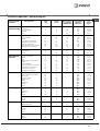
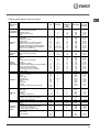
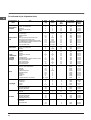
Oven cooking advice table
Cooking
modes
Foods Weight
(in kg)
Rack position Preheating
time
(min)
Recommended
temperature
Cooking
time
(minutes)
Convection
Oven
Duck
Roast veal or beef
Roast pork
Biscuits (shortcrust pastry)
Tarts
1
1
1
-
1
3
3
3
3
3
15
15
15
15
15
200
200
200
180
180
65-75
70-75
70-80
15-20
30-35
Baking mode
Tarts
Fruit cakes
Sponge cake made with
yoghurt
Sponge cake
Stuffed pancakes (on 2 racks)
Small cakes (on 2 racks)
Cheese puffs (on 2 racks)
Cream puffs (on 3 racks)
Biscuits (on 3 racks)
Meringues (on 3 racks)
0.5
1
0.7
0.5
1.2
0.6
0.4
0.7
0.7
0.5
3
2 or 3
3
3
2 and 4
2 and 4
2 and 4
1 and 3 and 5
1 and 3 and 5
1 and 3 and 5
15
15
15
15
15
15
15
15
15
15
180
180
180
160
200
190
210
180
180
90
20-30
40-45
40-50
25-30
30-35
20-25
15-20
20-25
20-25
180
Pizza Mode
Pizza
Roast veal or beef
Chicken
0.5
1
1
3
2
2 or 3
15
10
10
220
220
180
15-20
25-30
60-70
Multi-cooking
Pizza (on 2 racks)
Lasagne
Lamb
Roast chicken + potatoes
Mackerel
Sponge cake made with
yoghurt
Cream puffs (on 2 racks)
Biscuits (on 2 racks)
Sponge cake (on 1 rack)
Sponge cake (on 2 racks)
Savoury pies
1
1
1
1+1
1
1
0.5
0.5
0.5
1
1.5
2 and 4
3
2
2 and 4
2
2
2 and 4
2 and 4
2
2 and 4
3
15
10
10
15
10
10
10
10
10
10
15
230
180
180
200
180
170
190
180
170
170
200
15-20
30-35
40-45
60-70
30-35
40-50
20-25
10-15
15-20
20-25
25-30
Grill
Sole and cuttlefish
Squid and prawn kebabs
Cuttlefish
Cod fillet
Grilled vegetables
Veal steak
Sausages
Hamburgers
Mackerel
Toasted sandwiches (or toast)
0.7
0.6
0.6
0.8
0.4
0.8
0.6
0.6
1
n.° 4 and 6
4
4
4
4
3 or 4
4
4
4
4
4
100%
100%
100%
100%
100%
100%
100%
100%
100%
100%
10-12
8-10
10-15
10-15
15-20
15-20
15-20
10-12
15-20
3-5
Veal steak
Cutlets
Hamburgers
Mackerel
Toast
1
1
1
1
n.° 4
4
4
4
4
4
5
5
5
5
5
Max
Max
Max
Max
Max
15-20
15-20
7-10
15-20
2-3
Double Grill
With the rotisserie
Spit-roast veal
Spit-roast chicken
1.0
2.0
5
5
Max
Max
70-80
70-80
Grilled chicken
Cuttlefish
1.5
1.5
2
2
10
10
200
200
55-60
30-35
With the rotisserie
Spit-roast veal
Spit-roast chicken
Spit-roast lamb
1.5
1.5
1.5
5
5
5
200
200
200
70-80
70-80
70-80
Gratin
With multi-spit rotisserie
(selected models only)
Meat kebabs
Vegetable kebabs
1.0
0.8
5
5
Max
Max
40-45
25-30

12
GB
Precautions and tips
! This appliance has been designed and manufactured in
compliance with international safety standards.
The following warnings are provided for safety reasons
and must be read carefully.
General safety
• The appliance was designed for domestic use
inside the home and is not intended for
commercial or industrial use.
• The appliance must not be installed outdoors,
even in covered areas. It is extremely dangerous
to leave the appliance exposed to rain and
storms.
• Do not touch the appliance with bare feet or with
wet or damp hands and feet.
• The appliance must be used by adults only for the
preparation of food, in accordance with the
instructions outlined in this booklet. Any other use
of the appliance (e.g. for heating the room)
constitutes improper use and is dangerous. The
manufacturer may not be held liable for any
damage resulting from improper, incorrect and
unreasonable use of the appliance.
• The instruction booklet accompanies a class 1
(insulated) or class 2 - subclass 1 (recessed
between 2 cupboards) appliance.
• Keep children away from the oven.
• Make sure that the power supply cables of other
electrical appliances do not come into contact
with the hot parts of the oven.
• The openings used for the ventilation and
dispersion of heat must never be covered.
• Always use oven gloves when placing cookware
in the oven or when removing it.
• Do not use flammable liquids (alcohol, petrol,
etc...) near the appliance while it is in use.
• Do not place flammable material in the lower
storage compartment or in the oven itself. If the
appliance is switched on accidentally, it could
catch fire.
• Always make sure the knobs are in the “•”
position when the appliance is not in use.
• When unplugging the appliance, always pull the
plug from the mains socket; do not pull on the
cable.• Never perform any cleaning or
maintenance work without having disconnected
the appliance from the electricity mains.
• If the appliance breaks down, under no
circumstances should you attempt to repair the
appliance yourself. Repairs carried out by
inexperienced persons may cause injury or further
malfunctioning of the appliance. Contact
Assistance.
• Do not rest heavy objects on the open oven door.
• The appliance should not be operated by people
(including children) with reduced physical,
sensory or mental capacities, by inexperienced
individuals or by anyone who is not familiar with
the product. These individuals should, at the very
least, be supervised by someone who assumes
responsibility for their safety or receive
preliminary instructions relating to the operation of
the appliance.
• Do not let children play with the appliance.
Disposal
• When disposing of packaging material: observe local
legislation so that the packaging may be reused.
• The European Directive 2002/96/EC relating to Waste
Electrical and Electronic Equipment (WEEE) states that
household appliances should not be disposed of using
the normal solid urban waste cycle. Exhausted
appliances should be collected separately in order to
optimise the cost of re-using and recycling the
materials inside the machine, while preventing potential
damage to the atmosphere and to public health. The
crossed-out dustbin is marked on all products to
remind the owner of their obligations regarding
separated waste collection. For more information
relating to the correct disposal of household
appliances, owners should contact their local
authorities or appliance dealer.
Respecting and conserving the environment
• You can help to reduce the peak load of the electricity
supply network companies by using the oven in the
hours between late afternoon and the early hours of the
morning.
• Always keep the oven door closed when using the
GRILL, DOUBLE GRILL and GRATIN modes: this will
achieve better results while saving energy
(approximately 10%).
• Check the door seals regularly and wipe them clean to
ensure they are free of debris so that they adhere
properly to the door, thus avoiding heat dispersion.

GB
13
Switching the appliance off
Disconnect your appliance from the electricity
supply before carrying out any work on it.
Cleaning the appliance
! Never use steam cleaners or pressure cleaners on
the appliance.
• The stainless steel or enamel-coated external
parts and the rubber seals may be cleaned using
a sponge that has been soaked in lukewarm water
and neutral soap. Use specialised products for
the removal of stubborn stains. After cleaning,
rinse well and dry thoroughly. Do not use abrasive
powders or corrosive substances.
• The hob grids, burner caps, flame spreader rings
and burners may be removed to make cleaning
easier; wash them in hot water and non-abrasive
detergent, making sure all burnt-on residue is
removed before drying them thoroughly.
• For hobs with electronic ignition, the terminal part
of the electronic lighting devices should be
cleaned frequently and the gas outlet holes
should be checked for blockages.
• The inside of the oven should ideally be cleaned
after each use, while it is still lukewarm. Use hot
water and detergent, then rinse well and dry with
a soft cloth. Do not use abrasive products.
•
Clean the glass part of the oven door using a
sponge and a non-abrasive cleaning product,
then dry thoroughly with a soft cloth. Do not use
rough abrasive material or sharp metal scrapers
as these could scratch the surface and cause the
glass to crack.
• The accessories can be washed like everyday
crockery, and are even dishwasher safe.
Inspecting the oven seals
Check the door seals around the oven regularly. If
the seals are damaged, please contact your nearest
Authorised After-sales Service Centre. We
recommend that the oven is not used until the seals
have been replaced.
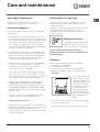
Replacing the oven light bulb
1. After disconnecting the oven from the electricity
mains, remove the glass lid covering the lamp
socket (
see figure
).
2. Remove the light bulb and replace it with a similar
one: voltage 230 V, wattage 25 W, cap E 14.
3. Replace the lid and reconnect the oven to the
electricity supply.
Gas tap maintenance
Over time, the taps may become
jammed or difficult to turn. If this
occurs, the tap must be replaced.
! This procedure must be performed by a
qualified technician who has been authorised by
the manufacturer.
Assistance
Please have the following information to hand:
• The appliance model (Mod.).
• The serial number (S/N).
This information can be found on the data plate
located on the appliance and/or on the packaging.
Care and maintenance
The cover
If the cooker is fitted with
a glass cover, this cover
should be cleaned using
lukewarm water. Do not
use abrasive products.
It is possible to remove
the cover in order to
make cleaning the area
behind the hob easier.
Open the cover fully and
pull it upwards (
see
figure
).
! Do not close the cover when the burners are alight
or when they are still hot.
! Remove any liquid from the lid before opening it.

14
PL
Spis treści
Instalacja, 15-18
Ustawienie i wypoziomowanie
Podłączenie do sieci elektrycznej
Podłączenie gazu
Dostosowanie do różnych rodzajów gazu
Tabela charakterystyk palników i dysz
Tabela charakterystyk
Opis urządzenia, 19
Widok ogólny
Panel kontrolny
Uruchomienie i użytkowanie, 20-25
Użytkowanie płyty grzejnej
Użytkowanie piekarnika
Programy pieczenia
Praktyczne porady dotyczące pieczenia
Tabela pieczenia w piekarniku
Zalecenia i środki ostrożności, 26
Ogólne zasady bezpieczeństwa
Zalecenia dotyczące odpadów
Oszczędność i ochrona środowiska
Konserwacja i utrzymanie, 27
Odłączenie prądu elektrycznego
Czyszczenie urządzenia
Wymiana żarówki oświetleniowej w piekarniku
Konserwacja kurków gazowych
Serwis Techniczny
Instrukcja obsługi
Polski, 14
PL
English,1
GB
KUCHENKA I PIEKARNIK
KN3T760SA/U
Eesti keeles,54
LV
LT
Latviešu,41
Lietuviu;28
ET

PL
PL
15
! Należy zachować niniejszą instrukcję, aby móc z
niej korzystać w każdej chwili. W przypadku
sprzedaży, odstąpienia lub przeniesienia urządzenia
należy upewnić się, czy instrukcja została
przekazana wraz z nim.
! Należy uważnie przeczytać instrukcję: zawiera ona
ważne informacje dotyczące instalacji, użytkowania i
bezpieczeństwa.
! Instalacja urządzenia powinna zostać wykonana
zgodnie z niniejszymi instrukcjami i przez
wykwalifikowany personel.
! Wszelkie działania w zakresie regulacji lub
konserwacji muszą być wykonywane przy kuchence
odłączonej od zasilania elektrycznego.
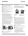
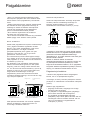
Wentylacja pomieszczeń
Urządzenie może zostać zainstalowane wyłącznie w
pomieszczeniach ze stałą wentylacją, zgodnie z
obowiązującymi normami krajowymi. W
pomieszczeniu, w którym jest instalowane
urządzenie, musi być zapewniony taki dopływ
powietrza, jaki jest niezbędny dla prawidłowego
spalania gazu (natężenie przepływu powietrza nie
powinno być niższe od 2 m
3
/h na kW zainstalowanej
mocy). Wloty powietrza, zabezpieczone przez kratki,
powinny mieć przewód o przekroju użytkowym co
najmniej 100 cm
2
i powinny zostać rozmieszczone
tak, aby nie mogły ulec nawet częściowemu zatkaniu
(patrz rysunek A).
Wymiar tych wlotów powinien zostać zwiększony o
100% – do minimum 200 cm
2
– jeśli płyta robocza
urządzenia nie posiada urządzenia
zabezpieczającego przed brakiem płomienia i kiedy
dopływ powietrza następuje w sposób pośredni z
przyległych pomieszczeń (patrz rysunek B) – o ile
nie są one częściami wspólnymi budynku,
pomieszczeniami zagrożonymi pożarem lub
sypialniami – wyposażonych w przewód
wentylacyjny z wyjściem na zewnątrz, jak opisano
powyżej.
A
Pomieszczenie przyległe
B
Pomieszczenie do wentylacji
! Po dłuższym użytkowaniu urządzenia zaleca się
otwarcie okna lub zwiększenie prędkości
ewentualnych wentylatorów.
Odprowadzanie spalin
Odprowadzanie spalin musi być zapewnione przez
okap połączony z kominem o ciągu naturalnym i o
sprawnym działaniu, lub przez wentylator
elektryczny, który włącza się automatycznie przy
każdym uruchomieniu urządzenia (patrz rysunki).
! Skroplone gazy pochodne ropy naftowej, cięższe od
powietrza, opadają w dół, dlatego pomieszczenia, w
których znajdują się butle LPG, powinny być
wyposażone w otwory wychodzące na zewnątrz,
umożliwiające odpływ ewentualnych wycieków gazu
dołem.
Butle LPG - niezależnie od tego, czy są puste, czy
częściowo napełnione - nie powinny być instalowane
ani składowane w pomieszczeniach lub wnękach
położonych poniżej poziomu podłogi (piwnice, itp.).
W pomieszczeniu należy przechowywać jedynie
aktualnie użytkowaną butlę, z dala od źródeł ciepła
(piece, kominki, piecyki), mogących doprowadzić do
wzrostu jej temperatury powyżej 50°C.
Ustawienie i wypoziomowanie
! Istnieje możliwość zainstalowania urządzenia obok
mebli, których wysokość nie przekracza wysokości
płyty roboczej.
! Należy upewnić się, czy ściana stykająca się z
tyłem urządzenia wykonana jest z materiału
niepalnego i odpornego na ciepło (T 90°C).
W celu zapewnienia prawidłowej instalacji:
• ustawić urządzenie w kuchni, w jadalni lub w
innym pomieszczeniu (nie w łazience);
• jeśli płaszczyzna kuchenki jest wyższa w
stosunku do płaszczyzny mebli, powinny one
zostać umieszczone w odległości co najmniej 600
mm od urządzenia;
Instalacja
A
Otwarcie wentylacji dla
powietrza do spalania
Zwiększenie szczeliny
pomiędzy drzwiami a
podłogą
Odprowadzanie
bezpośrednio na
zewnątrz
Odprowadzanie przez komin
lub rozgałęziony kanał
dymowy (wyłącznie do
urządzeń kuchennych)

16
PL
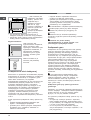
• jeśli kuchenka jest
instalowana pod szafką
wiszącą, powinna ona
znajdować się w
odległości minimum
420 mm od płyty
kuchenki. Odległość ta
powinna wynosić 700
mm, jeśli szafki
wiszące są łatwopalne
(patrz rysunek);
• nie umieszczać zasłon za kuchenką ani w
odległości mniejszej niż 200 mm od jej krawędzi;
• ewentualne okapy powinny zostać zainstalowane
według zaleceń odpowiedniej instrukcji.
Wypoziomowanie
Jeśli konieczne jest
wypoziomowanie urządzenia,
należy przykręcić nóżki
regulacyjne, dostarczone jako
wyposażenie dodatkowe, w
odpowiednich gniazdach
umieszczonych w rogach
podstawy kuchenki (patrz
rysunek).
Nóżki mocowane są w
otworach pod podstawą
kuchenki.
Podłączenie do sieci elektrycznej
Zamocować na przewodzie znormalizowaną wtyczkę,
dostosowaną do obciążeń wskazanych na tabliczce
znamionowej umieszczonej na urządzeniu (patrz
tabela Dane techniczne). W przypadku
bezpośredniego podłączenia do sieci konieczne jest
zainstalowanie pomiędzy urządzeniem a siecią
wyłącznika wielobiegunowego z minimalnym
otwarciem pomiędzy stykami wynoszącym 3 mm,
dostosowanego do obciążeń i odpowiadającego
obowiązującym normom krajowym (przewód
uziemienia nie powinien być przerwany przez
wyłącznik). Przewód zasilania powinien być
umieszczony tak, aby w żadnym punkcie jego
temperatura nie przekraczała temperatury otoczenia
o 50°C.
Przed wykonaniem podłączenia należy upewnić się,
czy:
• gniazdko posiada odpowiednie uziemienie i jest
zgodne z obowiązującymi przepisami;
• gniazdko jest w stanie wytrzymać maksymalne
obciążenie mocy urządzenia, wskazane na
tabliczce znamionowej;
HOOD
420
Min.
min. 650 mm. with hood
min.
700 mm. without hood
mm.
600
Min. mm.
420
Min. mm.
• napięcie zasilania odpowiada wartościom
podanym na tabliczce znamionowej;
• gniazdko jest kompatybilne z wtyczką urządzenia.
Jeśli gniazdko nie jest kompatybilne, należy
wymienić gniazdko lub wtyczkę; nie stosować
przedłużaczy ani rozgałęźników.
! Po zainstalowaniu urządzenia przewód elektryczny
i gniazdko prądu powinny być łatwo dostępne.
! Przewód nie powinien być powyginany ani
zgnieciony.
! Przewód musi być okresowo sprawdzany i
wymieniany wyłącznie przez autoryzowany personel
techniczny.
! Producent nie ponosi żadnej
odpowiedzialności za skutki wynikłe z nie
przestrzegania powyższych zasad.
Podłączenie gazu
Podłączenie do sieci gazowej lub do butli gazowej
może być wykonane przy pomocy przewodu
giętkiego gumowego lub stalowego, zgodnie z
obowiązującymi normami krajowymi, oraz po
upewnieniu się, czy urządzenie jest wyregulowane
odpowiednio dla typu gazu, którym będzie zasilane
(patrz etykieta kalibracyjna na pokrywie: w
przeciwnym razie patrz niżej). W przypadku
zasilania płynnym gazem z butli należy stosować
regulatory ciśnienia zgodne z obowiązującymi
normami krajowymi. Dla ułatwienia podłączenia
zasilanie gazem może być skierowane bocznie*:
zastąpić złączkę przewodu giętkiego zatyczką i
wymienić uszczelkę, dostarczoną jako wyposażenie
dodatkowe.
! W celu zapewnienia bezpieczeństwa pracy,
odpowiedniego zużycia energii i zwiększenia
trwałości urządzenia, należy się upewnić, czy
ciśnienie zasilania mieści się w granicach
wskazanych w tabeli „Charakterystyka palników i
dysz” (patrz niżej).
Podłączenie gazu przy pomocy przewodu
gumowego
Sprawdzić, czy przewód odpowiada obowiązującym
normom krajowym. Wewnętrzna średnica przewodu
powinna wynosić: 8 mm przy zasilaniu gazem
płynnym; 13 mm przy zasilaniu metanem.
Po wykonaniu podłączenia należy upewnić się, czy
przewód:
• nie styka się w żadnym punkcie z częściami,
które osiągają temperatury przekraczające 50°C;
• nie jest narażony na naciągnięcie ani poskręcanie
i nie ma na nim zagięć lub przewężeń;
• nie ma styczności z przedmiotami tnącymi,
ostrymi krawędziami, ruchomymi częściami, i nie
jest przygnieciony;

PL
PL
17
• jest łatwo dostępny na całej długości, co
umożliwia wykonywanie kontroli jego stanu;
• jego długość wynosi mniej niż 1500 mm;
• jest dobrze umocowany na dwóch końcach za
pomocą odpowiednich zacisków mocujących,
zgodnych z obowiązującymi normami krajowymi.
! Jeśli nie może być spełniony jeden lub kilka tych
warunków, albo jeśli kuchenka jest instalowana
zgodnie z warunkami klasy 2 - podklasy 1
(urządzenie umiejscowione pomiędzy dwoma
meblami), należy zastosować przewód giętki stalowy
(patrz niżej).
Podłączenie gazu przy pomocy przewodu
giętkiego ze stali nierdzewnej o pełnych
ściankach z gwintowanymi złączami.
Sprawdzić, czy przewód i uszczelki odpowiadają
obowiązującym normom krajowym.
Aby zamontować przewód, należy usunąć złączkę
przewodu giętkiego, znajdującą się na urządzeniu
(złącze wejściowe gazu do urządzenia jest
gwintowane gwintem gazowym 1/2 walcowym
męskim).
! Wykonać podłączenie tak, aby całkowita długość
przewodów nie przekraczała 2 metrów, oraz upewnić
się, czy przewód nie styka się z ruchomymi
częściami i nie jest przygnieciony.
Kontrola szczelności
Po zakończeniu instalacji sprawdzić szczelność
wszystkich złącz, stosując w tym celu roztwór
mydlany, nigdy płomień.
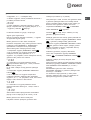
Dostosowanie do różnych rodzajów
gazu
Urządzenie może być dostosowane do innego
rodzaju gazu niż ten, którym jest aktualnie zasilane
(wskazany na etykiecie kalibracyjnej na pokrywie).
Dostosowanie płyty grzejnej
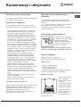
Wymiana dysz palników płyty:
1. zdjąć kratki i wykręcić palniki z gniazd;
2. odkręcić dysze, posługując się kluczem rurowym
7 mm (patrz rysunek), i
wymienić je na te, które są
przystosowane do nowego
rodzaju gazu (patrz tabela
„Charakterystyka palników i
dysz”);
3. przywrócić na swoje
miejsce wszystkie
komponenty, wykonując
czynności w kolejności odwrotnej w stosunku do
powyższej sekwencji.
Wymiana dysz w palniku „dwupłomieniowym” z
niezależnymi płomieniami
1. zdjąć kratki i wykręcić palniki z gniazd; palnik składa się
z dwóch oddzielnych części (patrz rysunki);
2. odkręcić dysze, posługując się kluczem rurowym 7
mm. Palnik wewnętrzny ma jedną dyszę, palnik
zewnętrzny ma dwie dysze (tej samej wielkości).
Wymienić dysze na dostosowane do nowego rodzaju
gazu (patrz tabela 1).
3. przywrócić na swoje miejsce wszystkie komponenty,
wykonując czynności w kolejności odwrotnej w
stosunku do powyższej sekwencji.
Regulacja minimum palników płyty:
1. ustawić kurek w położeniu minimum;
2. zdjąć pokrętło i kręcić śrubą regulacyjną
znajdującą się wewnątrz lub obok osi kurka aż do
uzyskania małego regularnego płomienia.
! W przypadku gazów płynnych śruba regulacyjna
powinna być dokręcona do końca;
3. sprawdzić, czy podczas szybkiego obracania
pokrętłem z położenia maksymalnego do
minimalnego nie następuje gaśnięcie palników.
! Palniki płyty nie wymagają regulacji powietrza
pierwotnego.
! Po wykonaniu regulacji dla gazu innego niż
oryginalnie przewidziany należy wymienić poprzednią
etykietę kalibracyjną na etykietę odpowiadającą
nowemu gazowi, dostępną w naszych
Autoryzowanych Centrach Obsługi Technicznej.
! W sytuacji, gdy ciśnienie gazu jest inne (lub
zmienne) od przewidzianego, konieczne jest
zainstalowanie regulatora ciśnienia na przewodach
doprowadzających, zgodnie z obowiązującą normą
krajową dotyczącą „kanałowych regulatorów gazu”.

18
PL
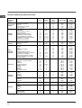
Tabela „Charakterystyka palników i dysz”
KN3T760SA/U
S
S
TC
A
DANE TECHNICZNE
Wymiary
piekarnika W x D
x G
39x41x34 cm
Objętość
(l) 54
Wymiary
użytkowe
szuflady do
podgrzewania
potraw
szerokość (cm) 42
głębokość (cm) 44
wysokość (cm) 23
Palniki
mogą być dostosowane do
wszystkich rodzajów gazu
wskazanych na tabliczce
znamionowej
Napięcie i
częstotliwość
zasilania
elektrycznego
patrz tabliczka znamionowa
ENERGY LABEL
Dyrektywa 2002/40/WE na
etykiecie piekarników elektrycznych
Norma EN 50304 Zużycie energii
konwekcja naturalna — funkcja
ogrzewania: Tradycyjne;
Zużycie energii deklaracja Klasa
konwekcji wymuszona — funkcja
ogrzewania:
Piekarnictwo
Dyrektywy unijne: 2006/95/EC z
dnia 12/12/06 (niskie napięcie) z
późniejszymi zmianami -
2004/108/EC z dnia 15/12/04
(zgodność elektromagnetyczna) z
późniejszymi zmianami -
93/68/EEC z dnia 22/07/93 z
późniejszymi zmianami,
90/396/EEC z dnia 29/06/90 (gaz)
z późniejszymi zmianami, -
93/68/EEC z dnia 22/07/93 z
późniejszymi zmianami, -
2002/96/EC.
1275/2008 (Stand-by/Off mode).
Tabela 1 (dla Polski) G20 (GZ50) G2.350 (GZ35) G30 (GPB)
Palnik
Śred
nica
(mm)
Moc
cieplna
(p.c.i.*)kW
minimal.
Moc
cieplna
(p.c.i.*)kW
nominal.
Dysza
1/100
(w mm)
Przepł
yw*
l/godz
Dysza
1/100
(w mm)
Przepływ*
l/godz
Moc cieplna
(p.c.i.*)
kW
nominal.
Dysza
1/100
(w mm)
Przepływ*
g/godz
Potrojna corona (TC) 130 1,50 3,25 133 309 197 430 3,60 91 262
Półszybki (średni) (S) 75 0,4 1,9 104 181 143 251 2,20 70 160
Pomocniczy (mały) (A) 51 0,4 1,0 76 95 106 132 1,30 52 95
Ciśnienia zasilania
minimalne (mbar)
nominalne (mbar)
maksymalne (mbar)
16
20
25
10
13
16
29
37
44
* A 15°C 1013 mbar – gaz suchy
G20 (GZ50) p.c.i. = 37,78 MJ/m³
G2.350 (GZ35) p.c.i. = 27,20 MJ/m³
G30
(
GPB
)
p
.c.i. = 125,81 MJ/m³

PL
PL
19
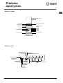
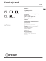
Opis urządzenia
Widok ogólny
Panel kontrolny
Kratka płyty grzejnej
Panel kontrolny
Poziom RUSZT
Poziom BRYTFANNA
PROWADNICE
przesuwania półek
pozycja 3
pozycja 2
pozycja 1
Palnik gazowy
Płyta zatrzymywania
ewentualnych wycieków
Nóżka regulowana
Nóżka regulowana
pozycja 5
pozycja 4
Szklana pokrywa
UWAGA! Szklana pokrywa może
popękać jeżeli zostanie nagrzana.
Należy wyłączyć wszystkie palniki
przed zamknięciem pokrywy.
*Dotyczy tylko modeli ze szklana
pokrywa.
Lampka kontrolna
TERMOSTATU
Elektroniczny
programator
pieczenia
TERMOSTATU
przycisk
KONIEC
CZASU PIECZENIA
przycisk
MINUTNIKA
przycisk
CZAS PIECZENIA

20
PL
Uruchomienie i
użytkowanie
Użytkowanie płyty grzejnej
Włączanie palników
Dla każdego pokrętła PALNIKA odpowiadający mu
palnik jest wskazany wypełnionym kółkiem.
W celu włączenia palnika na płycie grzejnej:
1. zbliżyć do palnika płomień lub zapalarkę;
2. nacisnąć i równocześnie przekręcić pokrętło
PALNIK w kierunku przeciwnym do ruchu wskazówek
zegara na symbol maksymalnego płomienia E.
3. ustawić żądany płomień, obracając pokrętłem
PALNIK w kierunku przeciwnym do ruchu wskazówek
zegara: na minimum C, na maksimum E lub na
pozycję pośrednią.
Jeśli urządzenie jest
wyposażone w zapłon
elektroniczny* (patrz rysunek),
wystarczy nacisnąć i
równocześnie przekręcić
pokrętło PALNIK w kierunku
przeciwnym do ruchu
wskazówek zegara na symbol
minimalnego płomienia, aż do zapalenia się palnika.
Może się zdarzyć, że palnik zgaśnie w chwili
zwolnienia pokrętła. W takim przypadku powtórzyć
czynność, trzymając pokrętło naciśnięte przez
dłuższą chwilę.
! W razie przypadkowego zgaśnięcia płomienia
należy wyłączyć palnik i odczekać przynajmniej 1
minutę przed ponowieniem próby jego zapalenia.
Jeśli palnik wyposażony jest w urządzenie
zabezpieczające* przed brakiem płomienia, należy
przytrzymać naciśnięte pokrętło PALNIKA przez
około 2-3 sekundy, aby utrzymać zapalony płomień i
uruchomić urządzenie.
W celu wyłączenia palnika przekręcić pokrętło aż do
zatrzymania •.
Palnik z „dwoma niezależnymi płomieniami ”*
Ten palnik gazowy składa się z dwóch
koncentrycznych płomieni, które mogą funkcjonować
łącznie lub w sposób niezależny od siebie.
Jednoczesne użycie dwóch płomieni ustawionych na
maksimum umożliwia znaczne zwiększenie mocy,
co ogranicza czas gotowania w stosunku do
tradycyjnych palników. Ponadto podwójna korona
płomieni sprawia, że rozkład ciepła na dnie naczynia
jest bardziej równomierny, zwłaszcza gdy obydwa
palniki są ustawione na minimum.
W celu jak najlepszego wykorzystania palnika z
podwójnym pomieniem nigdy nie należy
ustawiać jednocześnie wewnętrznej korony na
minimum i zewnętrznej na maksimum.
Można stosować naczynia dowolnej wielkości, w tym
przypadku dla małych naczyń wystarczy zapalić
jedynie wewnętrzny palnik. Każda pojedyncza
korona, która wchodzi w skład palnika o „dwóch
niezależnych płomieniach”, posiada własne pokrętło
regulacyjne.
W celu zapalenia wybranej korony należy wcisnąć
odpowiednie pokrętło do końca i obrócić w kierunku
przeciwnym do wskazówek zegara, aż do
maksymalnego położenia E. Palnik wyposażony jest
w zapłon elektroniczny, który uruchamia się
automatycznie po naciśnięciu pokrętła.
Ponieważ palnik wyposażony jest w urzdzenie
zabezpieczajce, konieczne jest przytrzymanie
wciśniętego pokrętła przez około 2-3 sekundy, aż
nagrzeje się urządzenie automatycznie
podtrzymujące zapalony płomień.
Wybrany palnik może być regulowany odpowiednim
pokrętłem w następujący sposób:
• Wyłączony
E Maksimum
C Minimum
Aby zgasić palnik, należy obrócić pokrętło zgodnie z
ruchem zegara aż do zatrzymania (odpowiadającego
symbolowi „•”).
Praktyczne rady w zakresie użytkowania
palników
W celu uzyskania lepszej wydajności palników oraz
zminimalizowania zużycia gazu należy stosować
naczynia o płaskim dnie, wyposażone w pokrywkę i
o rozmiarach proporcjonalnych w stosunku do
rozmiarów palnika:
W celu zidentyfikowania rodzaju palnika należy
zapoznać się z rysunkami znajdującymi się w części
„Charakterystyki palników i dysz”.
! W modelach wyposażonych w siatkę redukcyjną
powinna ona być stosowana wyłącznie dla palnika
pomocniczego, gdy używane są naczynia o średnicy
mniejszej niż 12 cm.
W kuchenkach z palnikiem DCDR siatka redukcyjna
powinna być stosowana wyłącznie na wewnętrznej
koronie palnika dwupłomieniowego (DCDR
wewnętrzny), gdy używane są naczynia o średnicy
mniejszej niż 12 cm.
Palnik ø Średnica naczyń (cm)
Potrójna korona (TC) 24 – 26
Średnio szybki (S) 16 – 20
Pomocniczy (A) 10 – 14
Strona się ładuje...
Strona się ładuje...
Strona się ładuje...
Strona się ładuje...
Strona się ładuje...
Strona się ładuje...
Strona się ładuje...
Strona się ładuje...
Strona się ładuje...
Strona się ładuje...
Strona się ładuje...
Strona się ładuje...
Strona się ładuje...
Strona się ładuje...
Strona się ładuje...
Strona się ładuje...
Strona się ładuje...
Strona się ładuje...
Strona się ładuje...
Strona się ładuje...
Strona się ładuje...
Strona się ładuje...
Strona się ładuje...
Strona się ładuje...
Strona się ładuje...
Strona się ładuje...
Strona się ładuje...
Strona się ładuje...
Strona się ładuje...
Strona się ładuje...
Strona się ładuje...
Strona się ładuje...
Strona się ładuje...
Strona się ładuje...
Strona się ładuje...
Strona się ładuje...
Strona się ładuje...
Strona się ładuje...
Strona się ładuje...
Strona się ładuje...
Strona się ładuje...
Strona się ładuje...
Strona się ładuje...
Strona się ładuje...
Strona się ładuje...
Strona się ładuje...
Strona się ładuje...
Strona się ładuje...
-
 1
1
-
 2
2
-
 3
3
-
 4
4
-
 5
5
-
 6
6
-
 7
7
-
 8
8
-
 9
9
-
 10
10
-
 11
11
-
 12
12
-
 13
13
-
 14
14
-
 15
15
-
 16
16
-
 17
17
-
 18
18
-
 19
19
-
 20
20
-
 21
21
-
 22
22
-
 23
23
-
 24
24
-
 25
25
-
 26
26
-
 27
27
-
 28
28
-
 29
29
-
 30
30
-
 31
31
-
 32
32
-
 33
33
-
 34
34
-
 35
35
-
 36
36
-
 37
37
-
 38
38
-
 39
39
-
 40
40
-
 41
41
-
 42
42
-
 43
43
-
 44
44
-
 45
45
-
 46
46
-
 47
47
-
 48
48
-
 49
49
-
 50
50
-
 51
51
-
 52
52
-
 53
53
-
 54
54
-
 55
55
-
 56
56
-
 57
57
-
 58
58
-
 59
59
-
 60
60
-
 61
61
-
 62
62
-
 63
63
-
 64
64
-
 65
65
-
 66
66
-
 67
67
-
 68
68


Indesit KN3T760SA(W)/U instrukcja
- Kategoria
- Mikrofale
- Typ
- instrukcja